EP1873714B1 - Appareil de traitement d'images et procédé pour améliorer la visibilité des images affichées - Google Patents
Appareil de traitement d'images et procédé pour améliorer la visibilité des images affichées Download PDFInfo
- Publication number
- EP1873714B1 EP1873714B1 EP07111020.9A EP07111020A EP1873714B1 EP 1873714 B1 EP1873714 B1 EP 1873714B1 EP 07111020 A EP07111020 A EP 07111020A EP 1873714 B1 EP1873714 B1 EP 1873714B1
- Authority
- EP
- European Patent Office
- Prior art keywords
- luminance
- contrast
- input image
- value
- saturation
- Prior art date
- Legal status (The legal status is an assumption and is not a legal conclusion. Google has not performed a legal analysis and makes no representation as to the accuracy of the status listed.)
- Active
Links
Images




Classifications
-
- G—PHYSICS
- G06—COMPUTING OR CALCULATING; COUNTING
- G06T—IMAGE DATA PROCESSING OR GENERATION, IN GENERAL
- G06T5/00—Image enhancement or restoration
- G06T5/90—Dynamic range modification of images or parts thereof
- G06T5/92—Dynamic range modification of images or parts thereof based on global image properties
-
- H—ELECTRICITY
- H04—ELECTRIC COMMUNICATION TECHNIQUE
- H04N—PICTORIAL COMMUNICATION, e.g. TELEVISION
- H04N5/00—Details of television systems
- H04N5/44—Receiver circuitry for the reception of television signals according to analogue transmission standards
- H04N5/57—Control of contrast or brightness
- H04N5/58—Control of contrast or brightness in dependence upon ambient light
-
- G—PHYSICS
- G06—COMPUTING OR CALCULATING; COUNTING
- G06T—IMAGE DATA PROCESSING OR GENERATION, IN GENERAL
- G06T2207/00—Indexing scheme for image analysis or image enhancement
- G06T2207/10—Image acquisition modality
- G06T2207/10024—Color image
-
- G—PHYSICS
- G06—COMPUTING OR CALCULATING; COUNTING
- G06T—IMAGE DATA PROCESSING OR GENERATION, IN GENERAL
- G06T2207/00—Indexing scheme for image analysis or image enhancement
- G06T2207/20—Special algorithmic details
- G06T2207/20081—Training; Learning
Definitions
- aspects of the present invention relate to an image processing apparatus and method, and more particularly, to an image processing apparatus and method which can prevent or reduce the deterioration of visibility of an image displayed on an image display device occurring under various lighting conditions when the brightness of ambient light is brighter than that of the image display device.
- small-sized digital devices such as mobile phones
- these related technologies may be classified into technologies for improving an image quality through signal processing and technologies for improving an image quality through a device change.
- the technologies for improving the image quality through signal processing include a color tonal contrast processing technology and a luminance tonal contrast processing technology.
- the related technologies for improving image quality through signal processing are disclosed, for example, in U.S. Patent No. 6,727,489 and Korean Patent Publication No. 2005-13767 .
- U.S. Patent No. 6,727,489 relates to an adaptive color processing technology using information regarding the brightness and color of ambient light of a projector or a reflective surface.
- the adaptive color processing technology fails to consider saturation and requires information regarding both the brightness and color of an external light source.
- Korean Patent Publication No. 2005-13767 relates to a technology for improving the contrast of a displayed image by minimizing de-fading according to changes in the luminance of the ambient light.
- this technology is simply directed to improving the contrast based on the luminance and does not consider the luminance and the saturation of an image.
- US 2004/0178974 A1 titled "Color OLED Display System Having Improved Performance” relates to an OLED display system including an OLED display including an array of light emitting pixels, each pixel having a plurality of OLEDs for emitting different colors of light specifying a gamut wherein one of the OLEDs has a power efficiency or lifetime different from the power efficiency or lifetime of at least one of the other OLEDs; a control signal; and a display driver for receiving a color display signal representing a relative luminance and color to be produced for each pixel of the display and generating a converted color display signal for driving the OLEDs in the display, wherein the display driver is responsive to the control signal for controlling the color gamut saturation of light produced by the OLEDs to reduce power consumption or increase lifetime of at least one of the OLEDs.
- WO 00/60855 titled "Apparatus for Processing Signals” relates to an apparatus for processing signals, comprising parameter control means for controlling parameters of signals in response to manual adjustments by a user as well as automatically generated adjustments based on current ambient factors or properties of said signals.
- This technique comprises indicator means for presenting a level indicator which is indicative of the combined result of the manual and automatic adjustments.
- an image processing apparatus is defined in claim 1.
- an image processing method is defined in claim 11.
- a computer-readable storage medium is defined in claim 20.
- FIG. 1 is a block diagram of an image processing apparatus 100 according to an aspect of the present invention.
- the image processing apparatus 100 includes a model setting unit (or a modeling unit) 110, a luminance sensor 120, a model storage unit 130, a luminance calculation unit 140, a contrast calculation unit 150, a luminance-contrast adjustment unit 160, and a saturation adjustment unit 170.
- the image processing apparatus 100 may be embedded or used in various image display devices, including displays, such as televisions (TVs), mobile phones, and/or projectors.
- displays such as televisions (TVs), mobile phones, and/or projectors.
- the modeling unit 110 receives a plurality of image samples (or sample images), and sets or generates an optimal relationship graph between a luminance (or a luminance value) and a contrast of one or more sample images for a particular external luminance (or an external luminance value).
- the modeling unit 110 also receives preferences (or inputs) from one or more users used to identify an optimal (or a preferred) contrast value according to the external luminance and according to the luminance of the sample images.
- a user may input one of a predetermined number of luminance values.
- the luminance sensor 120 receives an external light and senses an external luminance of an external environment in which the image processing apparatus 100 is situated.
- the luminance sensor 120 may be implemented using various technologies or devices known to those of ordinary skill in the art.
- the external luminance of the external environment sensed by the luminance sensor 120 may be provided to the luminance-contrast adjustment unit 160 or the modeling unit 110.
- the model storage unit 130 stores luminance-contrast model curves for various external luminances that are provided or generated by the modeling unit 110.
- the luminance calculation unit 140 calculates a luminance of an input image.
- the luminance (Y) can be obtained by calculating a weighted sum of a red (R), a green (G), and a blue (B) component or (RGB) components of an image.
- the luminance of an image is a representative value of the luminances of pixels include in the image.
- the representative value may be a mean, a median, or a mode value.
- the contrast calculation unit 150 calculates the contrast of the input image. There are various methods of calculating the contrast of an image, such as the input image. In aspects of the present invention, a cumulative distribution function (CDF) is used to calculate the contrast of the input image. The use of the CDF is discussed in detail in connection with FIG. 2 .
- CDF cumulative distribution function
- the luminance-contrast adjustment unit 160 determines the luminance and the contrast appropriate for the external luminance with reference to one or more luminance-contrast model curves stored in the modeling unit 130, and converts or adjusts the luminance and the contrast of the input image accordingly.
- the saturation adjustment unit 170 changes a saturation value of the input image according to the luminance and contrast adjusted or determined by the luminance-contrast adjustment unit 160.
- FIG. 2 illustrates a process of calculating a contrast of an input image according to an aspect of the present invention.
- the process may be performed by the contrast calculating unit 150.
- a cumulative distribution function (CDF) graph 21 of the luminance of the input image is shown.
- the CDF graph 21 is a cumulative frequency curve of the input image.
- a slope m_Slope of a line 22, connecting points 23 and 24 at which the CDF graph 21 meets a low range threshold value and a high range threshold value, respectively, may be considered to be the contrast value of the input image.
- the low and high range threshold values 23, 24 may be set arbitrarily, though not required.
- the low range threshold value 23 may be defined as a luminance value of the input image when the cumulative frequency thereof is 10 %
- the high range threshold value 24 may be defined as a luminance value of the input image when the cumulative frequency thereof is 90 %.
- the line 22 may pass through a point 25 at which a median value of the luminance of the input image meets the CDF graph 21. In other aspects, other percentage values or values of luminance are within the scope of the present invention.
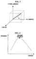
- FIG. 3 is a graph 30 illustrating the relationship among an external luminance, a luminance, and a contrast of a sample image, which may be set or generated by the modeling unit 110.
- the relationship graph 30 among these three variables i.e., the external luminance, the luminance, and the contrast
- a change in the luminance value of the image at a particular external luminance (or a given external luminance), as well as the contrast value that must be changed or adjusted accordingly can all be identified or determined.
- the modeling unit 110 receives input of preferences from a plurality of users, and is able to identify optimal contrast values according to the external luminance and the luminances of the sample images.
- the users may input one of a predetermined number of selections.
- the modeling unit 110 may contain predetermined preferences to identify optimal contrast values, or may obtain predetermined preferences from a source other than the plurality of users.
- the predetermined number of selections may be set as follows. Specifically, after a possible external luminance range is set or determined, one or more luminance intervals may be set or determined within the external luminance range. For example, if the possible external luminance range is 100 lux to 10,000 lux and the luminance interval is 100 lux, a total of 100 discrete external luminances (or luminance intervals) can be set. In other aspects, the luminance intervals need not necessarily be regularly spaced. Accordingly, the modeling unit 110 obtains or determines a luminance-contrast model curve for each interval of the external luminance, for example.
- the modeling unit 110 obtains user's preferences as the contrast is varied or changed.
- the preference according to the varying or changing contrast forms a curve, which is referred to as a reaction curve.
- a sample image is an 8-bit image
- the luminance of the sample image will have a range from 0 to 255.
- the modeling unit 110 obtains the reaction curve by repeatedly increasing the luminance of the sample image by 10 starting from 0 until 255 is reached.
- the luminance and/or the contrast may be selectable.
- the luminance-contrast model curve may be predetermined, obtained, or generated from a source other than the plurality of users, and may even be generated automatically without user input.
- FIG. 4 illustrates a reaction curve according to an aspect of the present invention.
- the modeling unit 110 receives preferences (or inputs) from a plurality of users while the contrast is changed from a minimum value to a maximum value for a particular luminance value (e.g., changing the slope of FIG. 2 ).
- the preferences according to the contrast have a distribution similar to that of a normal distribution resulting from the fact that it is difficult for users to perceive an image as being a natural looking image when the contrast of the image is either very low or very high. Therefore, the maximum preference point for the contrast is located in the middle of the reaction curve.
- the reaction curve may be collected to represent a graph of preferential contrast values for an entire range of luminances.
- FIG. 5 illustrates reaction curves 51, 52, and 53, similar to the reaction curve of FIG. 4 , which are depicted over an entire luminance range.
- a luminance-contrast model curve 50 can be obtained by interpolating the maximum preference points of the respective reaction curves 51, 52, and 53.
- the luminance-contrast model curve 50 best fits points 54, 55, and 56 of the maximum preferences of the reaction curves 51, 52, and 53, respectively obtained for each of the luminance levels.
- the horizontal axis indicates luminance values
- the vertical axis indicates optimal (or most preferred) contrast values corresponding to the luminance values.
- the luminance-contrast model curve 50 is for one external luminance. If the above discussed operation is repeatedly performed for all discrete external luminances, and then interpolated, luminance-contrast model curves for all external luminances can be obtained.
- the modeling unit 110 obtains one or more luminance-contrast model curves 50.
- Each of the obtained luminance-contrast model curves 50 is stored in the model storage unit 130 according to the various external luminances provided by the modeling unit 110.
- the he luminance-contrast adjustment unit 160 determines a luminance value and a contrast value appropriate for a current (detected) external luminance and converts or adjusts the luminance and contrast values of the input image into the above determined luminance and contrast values. To this end, the amount of change to be made in the luminance and contrast of the input image must be calculated.
- the amount of luminance change is the difference between the determined luminance value and the luminance value of the input image calculated by the luminance calculation unit 140.
- the amount of contrast change is the difference between the determined contrast value and the contrast value of the input image calculated by the contrast calculation unit 150.
- the luminance-contrast control unit 160 determines how much to change the luminance value of the input image, which is calculated by the luminance calculation unit 140, according to the current external luminance provided by the luminance sensor 120. In other words, the luminance-contrast adjustment unit 160 determines the amount of luminance change or adjusts a target luminance value.
- the luminance value of the input image may be designed to be proportional to the external luminance. Thus, if the external luminance increases by a predetermined rate, the luminance value of the input image may be increased accordingly.
- Various relational expressions other than a simple linear proportional expression can be used to obtain the relationship between the luminance and the external luminance as long as the proportional relationship between the luminance and the external luminance is maintained.
- the relationship between the luminance and the external luminance may be an exponential function and/or a logarithmic function.
- the luminance-contrast adjustment unit 160 obtains a contrast value corresponding to the above determined luminance value of the input image. Further, the luminance-contrast adjustment unit 160 adjusts the luminance of the current input image (or luminance level) to substantially or exactly match the determined target luminance value. Similarly, the luminance-contrast adjustment unit 160 adjusts the contrast of the current input image (or contrast level) having the adjusted luminance level to substantially or exactly match the above obtained contrast value.
- changing the luminance and the contrast of the input image based on the external luminance alone as described above may not be sufficient to provide an optimal image (or a natural looking image) to users.
- the saturation adjustment unit 170 changes or adjusts the saturation of the input image according to changes made in the luminance and the contrast.
- Methods of changing or adjusting the saturation of the input image include a method of directly changing a saturation component (S) in a hue/saturation/value (HSV) color space and a method of appropriately converting RGB components using a saturation matrix, among others.
- S saturation component
- HSV hue/saturation/value
- various saturation change methods are within the scope of the present invention.
- the saturation adjustment unit 170 changes the saturation value according to the luminance and contrast values determined by the luminance-contrast adjustment unit 160.
- the saturation adjustment unit 170 increases or decreases the saturation of the input image when the luminance and contrast values are increased or decreased, respectively. Accordingly, in this way, by adaptively changing the saturation of an output image according to changes in the luminance and contrast values, a natural looking image can be displayed or provided to users.
- the components illustrated in FIG. 1 may be implemented as software components such as tasks, classes, subroutines, processes, objects, executable threads, or programs performed in a predetermined region of a memory, or implemented as hardware components such as a Field Programmable Gate Array (FPGA) or Application Specific Integrated Circuit (ASIC).
- the components may be composed of a combination of the software and hardware components.
- FIG. 6 is a flowchart illustrating an image adjustment method according to an aspect of the present invention.
- the modeling unit 110 determines whether the input image is a sample image generated by a modeling process or an actual input image to be adjusted (operation S62). If the input image is a sample image, operation S71 and its subsequent operations are performed. If the input image is not a sample image, operation S81 and its subsequent operations are performed.
- the image adjustment method includes sensing the brightness of external light using the luminance sensor 120 (operation S81), calculating the luminance of the input image using the luminance calculation unit 140 and calculating the contrast of the input image using the contrast calculation unit 150 (operation S82), reading or obtaining the one or more luminance-contrast model curves stored in the model storage unit 130 (operation S83), determining a target luminance value according to the sensed brightness (or luminance) of the external light, obtaining the contrast value corresponding to the above determined target luminance value, and adjusting the input image to have the determined target luminance value and the obtained contrast value using the luminance-contrast adjustment unit 160 (operation S84), and/or adjusting the saturation of the adjusted input image according to the determined target luminance value and the obtained contrast value using the saturation adjustment unit 170 (operation S85).
- the luminance-contrast adjustment unit 160 adjusts the luminance value of the input image to that of the determined target luminance value and adjusts the contrast value of the input image having the adjusted luminance value to that of the obtained contrast value.
- the saturation adjustment unit 170 increases or decreases the saturation of the input image when the luminance and contrast of the input image are increased or decreased by the luminance-contrast adjustment unit 160.
- the saturation adjustment unit 170 may convert the input image with the adjusted luminance and contrast in an HSV color space and adjust a saturation component of the input image in the HSV color space.
- the saturation unit 170 may convert the luminance and contrast adjusted input image using a saturation matrix.
- the image adjustment method may further include calculating the luminance of the input image using the luminance calculation unit 140 and calculating the contrast of the input image using the contrast calculation unit 150 (operation S82).
- the luminance calculation unit 140 may calculate the luminance of the input image as a linear combination of the RGB components of the input image
- the contrast calculation unit 150 may calculate the contrast of the input image as the slope of a line connecting points at which a cumulative distribution function (CDF) according to the luminance of the input image meets a low range threshold value and a high range threshold value, respectively.
- CDF cumulative distribution function
- the line note above passes through a point at which the cumulative distribution function (CDF) and a median value of the luminance meet.
- the image adjustment method includes sensing the brightness of the external light (operation S71) and calculating the luminance and contrast of the sample image (operation S72). Also, the method includes obtaining contrast values having the user's maximum preference relating to a changing luminance of the sample image at a particular external luminance and generating a luminance-contrast model curve by interpolating points depicted by the contrast values (operation S73). The maximum preference may be determined based on input of preferences by a plurality of users.
- aspects of the present invention can enhance visibility of a display included in a digital device by providing a user with an image which dynamically responds to changes in external luminance.
- Various components of the image processing apparatus 100 can be integrated into a single control unit, or alternatively, can be implemented in software or hardware, such as, for example, a field programmable gate array (FPGA), or an application specific integrated circuit (ASIC).
- FPGA field programmable gate array
- ASIC application specific integrated circuit
- These software modules may include data and instructions which can also be stored on one or more machine-readable storage media, such as dynamic or static random access memories (DRAMs or SRAMs), erasable and programmable read-only memories (EPROMs), electrically erasable and programmable read-only memories (EEPROMs) and flash memories; magnetic disks such as fixed, floppy and removable disks; other magnetic media including tape; and optical media such as compact discs (CDs) or digital video discs (DVDs). Instructions of the software routines or modules may also be loaded or transported into the wireless cards or any computing devices on the wireless network in one of many different ways.
- DRAMs or SRAMs dynamic or static random access memories
- EPROMs erasable and programmable read-only memories
- EEPROMs electrically erasable and programmable read-only memories
- flash memories such as fixed, floppy and removable disks; other magnetic media including tape; and optical media such as compact discs (CDs) or digital video discs (DVDs).
- code segments including instructions stored on floppy discs, CD or DVD media, a hard disk, or transported through a network interface card, modem, or other interface device may be loaded into the system and executed as corresponding software routines or modules.
- data signals that are embodied as carrier waves (transmitted over telephone lines, network lines, wireless links, cables, and the like) may communicate the code segments, including instructions, to the network node or element.
- carrier waves may be in the form of electrical, optical, acoustical, electromagnetic, or other types of signals.
- the present invention can also be realized as computer readable codes on a computer readable recording medium.
- the computer readable recording medium is any data storage device that can store data which can be thereafter read by a computer system. Examples of the computer readable recording medium also include read-only memory (ROM), random-access memory (RAM), CD-ROMs, magnetic tapes, floppy disks, optical data storage devices, and carrier waves (such as data transmission through the Internet).
- ROM read-only memory
- RAM random-access memory
- CD-ROMs compact discs
- magnetic tapes magnetic tapes
- floppy disks optical data storage devices
- carrier waves such as data transmission through the Internet
- carrier waves such as data transmission through the Internet
- the computer readable recording medium can also be distributed over network coupled computer systems so that the computer readable code is stored and executed in a distributed fashion.
- functional programs, codes, and code segments for accomplishing the present invention can be easily construed by programmers skilled in the art to which the present invention pertains.
- the modeling unit 110 may contain predetermined preferences to identify optimal contrast values, or may obtain predetermined preferences from a source other than the plurality of users.
- the luminance and/or the contrast may both be preferentially selectable.
- the luminance-contrast model curve may be predetermined, obtained, or generated from a source other than the plurality of users, and may even be done automatically without user input.
- the reaction curve may be collected to represent a graph of preferential contrast values for an entire range of luminances.
- the relationship between the luminance and the external luminance may be an exponential function and/or a logarithmic function.
- Various saturation change methods are within the scope of the present invention.
Landscapes
- Engineering & Computer Science (AREA)
- Physics & Mathematics (AREA)
- General Physics & Mathematics (AREA)
- Theoretical Computer Science (AREA)
- Multimedia (AREA)
- Signal Processing (AREA)
- Controls And Circuits For Display Device (AREA)
- Image Processing (AREA)
- Television Receiver Circuits (AREA)
Claims (22)
- Appareil de traitement d'image comprenant :un capteur de luminance (120) pour capter la luminance d'une lumière externe ;une unité de stockage de modèle (130) pour stocker une courbe de modèle luminance-contraste (50) représentant une valeur de contraste optimale pour un niveau de luminance particulier (1, ... , n) de chaque luminance de la lumière externe ;une unité de réglage luminance-contraste (160) pour déterminer une valeur de luminance cible comme étant proportionnelle à la luminance détectée de la lumière externe, pour obtenir une valeur de contraste correspondant à la valeur de luminance cible en référence à la courbe de modèle luminance-contraste (50) correspondant à la luminance détectée de la lumière externe, et pour régler la valeur de luminance d'une image d'entrée pour qu'elle ait la valeur de luminance cible et pour régler une valeur de contraste de l'image d'entrée pour qu'elle ait la valeur de contraste obtenue ; etune unité de réglage de saturation (170) pour régler la saturation de l'image d'entrée réglée en fonction de la valeur de luminance cible et de la valeur de contraste obtenue,dans lequel l'appareil comprend en outre une unité de modélisation (110) pour obtenir la courbe de modèle luminance-contraste (50) en obtenant des valeurs de contraste de points de préférence maximale de courbes réactives (51, 52, 53) tout en changeant la luminance d'une image échantillon, lesdites courbes réactives étant obtenues en augmentant de manière répétée la luminance de l'image échantillon pour chacun des niveaux de luminance et en interpolant les points de préférence maximale représentés par les valeurs de contraste obtenues.
- Appareil selon la revendication 1, comprenant en outre :une unité de calcul de luminance (140) adaptée pour calculer la valeur de luminance de l'image d'entrée ; etune unité de calcul de contraste (150) adaptée pour calculer la valeur de contraste de l'image d'entrée.
- Appareil selon la revendication 2, dans lequel l'unité de calcul de luminance (140) est en outre adaptée pour calculer la luminance de l'image d'entrée comme une combinaison linéaire de composantes rouge, vert et bleu, soit RVB, de l'image d'entrée.
- Appareil selon la revendication 2, dans lequel l'unité de calcul de contraste (150) est en outre adaptée pour calculer le contraste de l'image d'entrée sous forme de la pente d'une ligne qui relie des points où une fonction de distribution cumulative atteint respectivement une valeur seuil de plage basse et une valeur seuil de plage haute.
- Appareil selon la revendication 4, dans lequel la ligne passe par un point où se rencontrent la fonction de distribution cumulative et une valeur médiane de la luminance de l'image d'entrée.
- Appareil selon la revendication 1, dans lequel l'unité de modélisation (110) est adaptée pour déterminer la préférence maximale sur base d'une entrée de préférences par un ou plusieurs utilisateurs.
- Appareil selon la revendication 1, dans lequel l'unité de réglage luminance-contraste (160) est adaptée pour régler la valeur de luminance de l'image d'entrée à celle de la valeur de luminance cible, et pour régler la valeur de contraste de l'image d'entrée ayant la valeur de luminance réglée à celle de la valeur de contraste obtenue.
- Appareil selon la revendication 1, dans lequel l'unité de réglage de saturation (170) est adaptée pour régler la saturation en augmentant ou en diminuant la saturation de l'image d'entrée quand la luminance et le contraste de l'image d'entrée sont augmentés ou diminués par l'unité de réglage luminance-contraste (160).
- Appareil selon la revendication 8, dans lequel l'unité de réglage de saturation (170) est en outre adaptée pour convertir l'image d'entrée ayant la luminance et le contraste réglés dans un espace colorimétrique Teinte Saturation Valeur, TSV, et pour régler une composante de saturation de l'image d'entrée dans l'espace colorimétrique TSV.
- Appareil selon la revendication 8, dans lequel l'unité de réglage de saturation (170) est en outre adaptée pour convertir l'image d'entrée ayant le contraste et la luminance réglés en utilisant une matrice de saturation.
- Procédé de traitement d'image, comprenant :la détection (S71, S81) de la luminance d'une lumière externe ;la lecture (S83) d'une courbe de modèle luminance-contraste (50) représentant une valeur de contraste optimale pour un niveau de luminance particulier (1, ... , n) de chaque luminance de la lumière externe ;la détermination d'une valeur de luminance cible comme étant proportionnelle à la luminance détectée de la lumière externe, l'obtention d'une valeur de contraste correspondant à la valeur de luminance cible en référence à la courbe de modèle luminance-contraste (50) correspondant à la luminance détectée de la lumière externe, et le réglage (S84) d'une image d'entrée pour qu'elle ait la valeur de luminance cible et la valeur de contraste obtenue ; etle réglage de la saturation (S85) de l'image d'entrée réglée en fonction de la valeur de luminance cible et de la valeur de contraste obtenue,dans lequel le procédé comprend en outre l'obtention de la courbe de modèle luminance-contraste (50) en obtenant des valeurs de contraste de points de préférence maximale de courbes réactives (51, 52, 53) tout en changeant la luminance d'une image échantillon, lesdites courbes réactives étant obtenues en augmentant de manière répétée la luminance de l'image échantillon pour chacun des niveaux de luminance et en interpolant les points de préférence maximale représentés par les valeurs de contraste obtenues.
- Procédé selon la revendication 11, comprenant en outre :le calcul de la luminance de l'image d'entrée ; etle calcul du contraste de l'image d'entrée.
- Procédé selon la revendication 12, dans lequel le calcul de la luminance comprend le calcul de la luminance de l'image d'entrée sous forme d'une combinaison linéaire de composantes RVB de l'image d'entrée.
- Procédé selon la revendication 12, dans lequel le calcul du contraste comprend le calcul du contraste de l'image d'entrée sous forme de la pente d'une ligne qui relie des points où une fonction de distribution cumulative atteint respectivement une valeur seuil de plage basse et une valeur seuil de plage haute.
- Procédé selon la revendication 11, comprenant en outre la détermination de la préférence maximale sur base de l'entrée de préférences par un ou plusieurs utilisateurs.
- Procédé selon la revendication 11, dans lequel la détermination de la valeur de luminance cible comprend :le réglage (S84) d'une valeur de luminance de l'image d'entrée à la valeur de luminance cible ; etle réglage d'une valeur de contraste de l'image d'entrée ayant la valeur de luminance réglée à celle de la valeur de contraste obtenue.
- Procédé selon la revendication 11, dans lequel le réglage de la saturation (S85) de l'image d'entrée réglée comprend :l'augmentation de la saturation de l'image d'entrée quand la luminance et le contraste de l'image d'entrée sont augmentés après le réglage de l'image d'entrée ; etla diminution de la saturation de l'image d'entrée quand la luminance et le contraste de l'image d'entrée sont diminués après le réglage de l'image d'entrée.
- Procédé selon la revendication 11, dans lequel le réglage de la saturation de l'image d'entrée réglée comprend :la conversion de l'image d'entrée ayant la luminance et le contraste réglés dans un espace colorimétrique TSV ; etle réglage d'une composante de saturation de l'image d'entrée dans l'espace colorimétrique TSV.
- Procédé selon la revendication 11, dans lequel le réglage de la saturation de l'image d'entrée réglée comprend la conversion de l'image d'entrée ayant la luminance et le contraste réglés en utilisant une matrice de saturation.
- Support de stockage lisible par un ordinateur comportant des instructions pour mettre en oeuvre un traitement d'image, quand elles sont exécutées par un processeur, pour commander au processeur de mettre en oeuvre les étapes suivantes :détection (S81) d'une luminance externe d'un environnement externe ;détection (S82) d'une luminance d'entrée et d'un contraste d'entrée d'une image d'entrée ;obtention (S83) d'une ou plusieurs courbes de modèle luminance-contraste stockées (50) correspondant à la luminance externe, dans lequel une courbe de modèle luminance-contraste (50) représente une valeur de contraste optimale pour un niveau de luminance particulier (1, ... , n) ;détermination d'une luminance cible comme étant proportionnelle à la luminance d'entrée détectée et d'un contraste cible correspondant à la luminance cible à partir d'au moins une des courbes de modèle luminance-contraste stockées (50) ; etréglage de la luminance d'entrée et du contraste d'entrée de l'image d'entrée respectivement à la luminance cible et au contraste cible, pour l'affichage subséquent de l'image d'entrée,dans lequel le procédé comprend en outre l'obtention de la courbe de modèle luminance-contraste (50) en obtenant des valeurs de contraste de points de préférence maximale de courbes réactives (51, 52, 53) tout en changeant la luminance d'une image échantillon, lesdites courbes réactives étant obtenues en augmentant de manière répétée la luminance de l'image échantillon pour chacun des niveaux de luminance et en interpolant les points de préférence maximale représentés par les valeurs de contraste obtenues.
- Support de stockage selon la revendication 20, comprenant en outre le réglage d'une saturation de l'image d'entrée réglée en fonction de la luminance cible et du contraste cible.
- Support de stockage selon la revendication 20, dans lequel lesdites une ou plusieurs courbes de modèle luminance-contraste stockées (50) comprennent une relation entre la luminance externe, la luminance cible et/ou le contraste cible.
Applications Claiming Priority (1)
| Application Number | Priority Date | Filing Date | Title |
|---|---|---|---|
| KR1020060058217A KR100763239B1 (ko) | 2006-06-27 | 2006-06-27 | 디스플레이되는 영상의 시인성 향상을 위한 영상 처리 장치및 방법 |
Publications (3)
| Publication Number | Publication Date |
|---|---|
| EP1873714A2 EP1873714A2 (fr) | 2008-01-02 |
| EP1873714A3 EP1873714A3 (fr) | 2013-09-04 |
| EP1873714B1 true EP1873714B1 (fr) | 2015-06-24 |
Family
ID=38473999
Family Applications (1)
| Application Number | Title | Priority Date | Filing Date |
|---|---|---|---|
| EP07111020.9A Active EP1873714B1 (fr) | 2006-06-27 | 2007-06-26 | Appareil de traitement d'images et procédé pour améliorer la visibilité des images affichées |
Country Status (4)
| Country | Link |
|---|---|
| US (1) | US8913194B2 (fr) |
| EP (1) | EP1873714B1 (fr) |
| KR (1) | KR100763239B1 (fr) |
| CN (1) | CN101098489B (fr) |
Families Citing this family (54)
| Publication number | Priority date | Publication date | Assignee | Title |
|---|---|---|---|---|
| JP2009503544A (ja) * | 2005-08-01 | 2009-01-29 | バイオプティジェン,インコーポレイテッド | 試料から取得された3次元データセットを解析する方法、システム及びコンピュータ・プログラムプロダクト |
| US20100188443A1 (en) * | 2007-01-19 | 2010-07-29 | Pixtronix, Inc | Sensor-based feedback for display apparatus |
| KR20090057827A (ko) * | 2007-12-03 | 2009-06-08 | 삼성전자주식회사 | 3d 영상의 색을 변환하는 장치 및 방법 |
| JP5491702B2 (ja) * | 2008-03-28 | 2014-05-14 | 株式会社東芝 | 画像表示装置および画像表示方法 |
| EP2133861A3 (fr) * | 2008-06-10 | 2010-07-28 | LG Electronics, Inc. | Dispositif d'affichage et son procédé de contrôle |
| KR101149216B1 (ko) | 2009-01-21 | 2012-05-25 | 엘지전자 주식회사 | 디스플레이장치 및 그의 제어 방법 |
| US8311361B2 (en) * | 2008-08-21 | 2012-11-13 | Hong Kong Applied Science and Technology Research Institute Company Limited | Digital image enhancement |
| CN101578855B (zh) * | 2008-08-28 | 2015-07-29 | 香港应用科技研究院有限公司 | 数字图像增强 |
| TWI399100B (zh) * | 2009-03-06 | 2013-06-11 | 勝華科技股份有限公司 | 影像處理方法 |
| CN101841724B (zh) * | 2009-03-20 | 2011-09-28 | 胜华科技股份有限公司 | 图像处理方法 |
| CN101887692B (zh) * | 2009-05-13 | 2012-08-22 | 胜华科技股份有限公司 | 影像显示方法 |
| KR101073568B1 (ko) * | 2009-08-27 | 2011-10-14 | 삼성모바일디스플레이주식회사 | 표시 장치 및 그 구동 방법 |
| CN101742084B (zh) * | 2010-01-29 | 2012-05-30 | 昆山锐芯微电子有限公司 | 对比度增强处理方法与处理装置 |
| US20120308155A1 (en) * | 2010-02-11 | 2012-12-06 | Sharp Kabushiki Kaisha | Image processor, display device, and image processing method |
| US8744159B2 (en) * | 2010-03-05 | 2014-06-03 | Bioptigen, Inc. | Methods, systems and computer program products for collapsing volume data to lower dimensional representations thereof using histogram projection |
| KR101248902B1 (ko) | 2010-10-13 | 2013-04-01 | 에스케이하이닉스 주식회사 | 주변 조도에 따른 영상 보정 기능을 갖는 영상 처리 장치 및 영상 처리 방법 |
| US8749538B2 (en) | 2011-10-21 | 2014-06-10 | Qualcomm Mems Technologies, Inc. | Device and method of controlling brightness of a display based on ambient lighting conditions |
| JP5950628B2 (ja) * | 2012-03-07 | 2016-07-13 | 株式会社日立国際電気 | 物体検知装置、物体検知方法及びプログラム |
| US9183812B2 (en) | 2013-01-29 | 2015-11-10 | Pixtronix, Inc. | Ambient light aware display apparatus |
| CN104299600B (zh) * | 2013-07-18 | 2016-12-07 | 联咏科技股份有限公司 | 图像显示装置及其图像优化方法 |
| US9377291B2 (en) | 2013-12-05 | 2016-06-28 | Bioptigen, Inc. | Image registration, averaging, and compounding for high speed extended depth optical coherence tomography |
| CN103763537A (zh) * | 2014-01-06 | 2014-04-30 | 深圳Tcl新技术有限公司 | 动态调节显示画质的方法和装置 |
| KR102207939B1 (ko) * | 2014-03-27 | 2021-01-26 | 한화테크윈 주식회사 | 안개 제거 시스템 및 안개 제거 방법 |
| KR20150140514A (ko) | 2014-06-05 | 2015-12-16 | 삼성디스플레이 주식회사 | 투명 디스플레이 장치의 색 보상 방법 |
| KR102244918B1 (ko) * | 2014-07-11 | 2021-04-27 | 삼성전자주식회사 | 시인성을 향상시키고 전력 소모를 줄일 수 있는 디스플레이 컨트롤러와 이를 포함하는 디스플레이 시스템 |
| US9934730B2 (en) | 2014-11-19 | 2018-04-03 | Samsung Electronics Co., Ltd. | Computing device and image processing method thereof |
| KR102189643B1 (ko) | 2014-12-30 | 2020-12-11 | 삼성전자주식회사 | 디스플레이 장치 및 그 제어 방법 |
| CN104795022B (zh) * | 2015-03-26 | 2017-09-29 | 繁昌县倍思生产力促进中心有限公司 | 一种光强自适应型led显示屏 |
| KR102390918B1 (ko) * | 2015-05-08 | 2022-04-26 | 한화테크윈 주식회사 | 안개 제거 시스템 |
| CN105304064B (zh) * | 2015-11-03 | 2017-09-12 | 广东欧珀移动通信有限公司 | 调节电子设备屏幕亮度的方法和系统 |
| JP6523151B2 (ja) * | 2015-12-09 | 2019-05-29 | 富士フイルム株式会社 | 表示装置 |
| EP3318056A4 (fr) | 2015-12-22 | 2019-03-20 | Hewlett-Packard Development Company, L.P. | Images à couleur corrigée pour des projecteurs |
| KR102499305B1 (ko) * | 2016-01-21 | 2023-02-14 | 삼성디스플레이 주식회사 | 표시 장치, 표시 장치의 구동 방법, 및 표시 장치를 포함하는 전자 장치 |
| KR102478606B1 (ko) | 2016-07-18 | 2022-12-16 | 삼성전자주식회사 | 영상 표시 장치 및 영상 표시 방법 |
| CN108307139A (zh) * | 2017-01-11 | 2018-07-20 | 华为技术有限公司 | 一种图像调节的方法、视频会议终端及视频会议系统 |
| CN107016978B (zh) * | 2017-04-25 | 2018-11-20 | 腾讯科技(深圳)有限公司 | 一种界面展示技术及终端设备 |
| CN109982012B (zh) * | 2017-12-28 | 2021-06-25 | 展讯通信(上海)有限公司 | 图像处理方法及装置、存储介质、终端 |
| CN108492757B (zh) * | 2018-03-30 | 2021-10-08 | 厦门天马微电子有限公司 | 投射显示装置的驱动方法、驱动单元及投射显示装置 |
| CN109729281A (zh) * | 2019-01-04 | 2019-05-07 | Oppo广东移动通信有限公司 | 图像处理方法、装置、存储介质及终端 |
| CN109978881B (zh) * | 2019-04-09 | 2021-11-26 | 苏州浪潮智能科技有限公司 | 一种图像显著性处理的方法和装置 |
| US11430093B2 (en) * | 2019-10-01 | 2022-08-30 | Microsoft Technology Licensing, Llc | Face-based tone curve adjustment |
| CN110766636B (zh) * | 2019-10-28 | 2022-06-07 | 河南大学 | 一种用于ai芯片的智能图像处理方法 |
| CN111698442B (zh) * | 2020-06-16 | 2022-10-04 | 深圳康佳电子科技有限公司 | 一种图像对比度调整方法、显示装置及存储介质 |
| CN112327494A (zh) * | 2020-10-29 | 2021-02-05 | 中国航空工业集团公司洛阳电光设备研究所 | 机载平视显示器自动亮度调节方法 |
| CN113140197B (zh) * | 2021-04-21 | 2023-05-05 | Oppo广东移动通信有限公司 | 显示画面调节方法和装置、电子设备、可读存储介质 |
| CN115602136B (zh) * | 2021-06-28 | 2025-10-28 | Oppo广东移动通信有限公司 | 亮度调整方法及装置、电子设备、存储介质 |
| CN113628137B (zh) * | 2021-08-03 | 2024-04-16 | 武汉三江中电科技有限责任公司 | 一种光线不足环境下的图像增强算法及装置 |
| CN114422767B (zh) * | 2022-01-29 | 2024-09-10 | Oppo广东移动通信有限公司 | 一种视频效果增强方法、装置、移动终端和存储介质 |
| US20230351562A1 (en) * | 2022-04-28 | 2023-11-02 | Samsung Electronics Co., Ltd. | Standard dynamic range (sdr) to high dynamic range (hdr)inverse tone mapping using machine learning |
| CN117690389B (zh) * | 2022-09-05 | 2026-03-31 | 北京字跳网络技术有限公司 | 显示设备的调节方法、装置、设备、存储介质及ar眼镜 |
| CN116256936A (zh) * | 2023-03-27 | 2023-06-13 | 广东远合工程科技有限公司 | 一种亮度控制方法、装置、电子设备和存储介质 |
| KR20240156211A (ko) | 2023-04-21 | 2024-10-29 | 삼성전자주식회사 | 영상 처리 장치 및 이의 영상 처리 방법 |
| CN119229816B (zh) * | 2023-06-28 | 2025-11-11 | 广州视源电子科技股份有限公司 | 显示屏对比度恒定方法、显示屏及存储介质 |
| CN119229829B (zh) * | 2024-09-24 | 2025-10-10 | 江苏和熠光显科技有限公司 | 一种基于人工智能的oled显示器亮度对比度组合调节系统 |
Family Cites Families (32)
| Publication number | Priority date | Publication date | Assignee | Title |
|---|---|---|---|---|
| DE4010836A1 (de) * | 1990-04-04 | 1991-10-10 | Wabco Westinghouse Fahrzeug | Mehrpolige elektrische steckvorrichtung |
| KR0177937B1 (ko) * | 1994-08-04 | 1999-05-01 | 구자홍 | 영상표시기기의 영상 자동 보정 장치와 방법 |
| JPH09149337A (ja) * | 1995-10-24 | 1997-06-06 | Chishu Denno Kofun Yugenkoshi | ディスプレイで輝度とコントラストを自動制御するシステムと方法 |
| JP3736632B2 (ja) | 1996-11-21 | 2006-01-18 | セイコーエプソン株式会社 | 画像処理装置、画像処理方法および画像処理プログラムを記録した媒体 |
| EP0963111A1 (fr) | 1998-06-02 | 1999-12-08 | Deutsche Thomson-Brandt Gmbh | Méthode et appareil d'amélioration dynamique du contraste dans des images vidéo |
| KR100299759B1 (ko) * | 1998-06-29 | 2001-10-27 | 구자홍 | 영상표시기기의 화면 상태 자동 조정 장치와 방법 |
| WO2000060855A1 (fr) * | 1999-04-06 | 2000-10-12 | Koninklijke Philips Electronics N.V. | Appareil permettant de traiter des signaux |
| KR100388287B1 (ko) | 1999-06-07 | 2003-06-19 | 앰코 테크놀로지 코리아 주식회사 | 웨이퍼의 백그라인딩 방법과 이를 이용한 반도체패키지 및 그 제조방법 |
| KR20010001597U (ko) * | 1999-06-30 | 2001-01-15 | 윤종용 | 광센서를 이용한 화질개선장치 |
| US6778691B1 (en) * | 2000-05-16 | 2004-08-17 | Eastman Kodak Company | Method of automatically determining tone-scale parameters for a digital image |
| KR100366300B1 (ko) | 2000-06-17 | 2002-12-31 | 차동호 | 박막 트랜지스터 액정 표시 장치 및 그와 유사한 화상표시 장치의 화상 표시 제어 시스템 |
| JP2002311503A (ja) | 2001-04-19 | 2002-10-23 | Mitsubishi Electric Corp | 画質補正システム |
| CN1303570C (zh) * | 2002-02-12 | 2007-03-07 | 松下电器产业株式会社 | 图象处理装置和图象处理方法 |
| US7119837B2 (en) * | 2002-06-28 | 2006-10-10 | Microsoft Corporation | Video processing system and method for automatic enhancement of digital video |
| BRPI0302384B1 (pt) * | 2002-07-20 | 2018-06-19 | Samsung Electronics Co., Ltd. | "método para intensificar de forma adaptativa uma cor, e equipamento para intensificar de forma adaptativa a cor de uma imagem" |
| US7397485B2 (en) | 2002-12-16 | 2008-07-08 | Eastman Kodak Company | Color OLED display system having improved performance |
| JP2004252620A (ja) | 2003-02-19 | 2004-09-09 | Sony Corp | 画像処理装置および方法、並びに、プログラム |
| US7365880B2 (en) * | 2003-04-04 | 2008-04-29 | Kabushiki Kaisha Toshiba | Image processing apparatus and image processing method |
| JP2004354872A (ja) | 2003-05-30 | 2004-12-16 | Mitsubishi Electric Corp | 携帯型電子機器 |
| KR20050013767A (ko) | 2003-07-29 | 2005-02-05 | 삼성전자주식회사 | 휴대 단말기에서 영상화면의 밝기 조절 방법 |
| US7428333B2 (en) * | 2004-01-23 | 2008-09-23 | Old Dominion University | Visibility improvement in color video stream |
| JP2005227436A (ja) | 2004-02-12 | 2005-08-25 | Matsushita Electric Ind Co Ltd | 液晶表示装置 |
| JP4470587B2 (ja) | 2004-05-27 | 2010-06-02 | パナソニック株式会社 | 画像表示装置 |
| JP4324043B2 (ja) * | 2004-07-15 | 2009-09-02 | キヤノン株式会社 | 画像処理装置およびその方法 |
| JP2006119200A (ja) | 2004-10-19 | 2006-05-11 | Fujitsu General Ltd | 映像表示装置 |
| US8131108B2 (en) * | 2005-04-22 | 2012-03-06 | Broadcom Corporation | Method and system for dynamic contrast stretch |
| US7352410B2 (en) * | 2005-05-31 | 2008-04-01 | Kolorific, Inc. | Method and system for automatic brightness and contrast adjustment of a video source |
| US20070053587A1 (en) * | 2005-08-24 | 2007-03-08 | Ali Walid S | Techniques to improve contrast enhancement using a luminance histogram |
| TW200719731A (en) * | 2005-11-07 | 2007-05-16 | Cheertek Inc | Method for adjusting hue and color saturation by matrix |
| US7817873B2 (en) * | 2005-11-09 | 2010-10-19 | Intel Corporation | Enhancing contrast of video data while preserving sharpness |
| EP1801767A1 (fr) * | 2005-12-23 | 2007-06-27 | Research In Motion Limited | Procédé et dispositif pour régler ou modifier des propriétés d'éléments sur un affichage visuel basé sur la lumière ambiante |
| US20070285516A1 (en) * | 2006-06-09 | 2007-12-13 | Brill Michael H | Method and apparatus for automatically directing the adjustment of home theater display settings |
-
2006
- 2006-06-27 KR KR1020060058217A patent/KR100763239B1/ko active Active
-
2007
- 2007-06-26 CN CN200710112669XA patent/CN101098489B/zh active Active
- 2007-06-26 US US11/768,412 patent/US8913194B2/en active Active
- 2007-06-26 EP EP07111020.9A patent/EP1873714B1/fr active Active
Also Published As
| Publication number | Publication date |
|---|---|
| US8913194B2 (en) | 2014-12-16 |
| CN101098489A (zh) | 2008-01-02 |
| KR100763239B1 (ko) | 2007-10-04 |
| EP1873714A3 (fr) | 2013-09-04 |
| EP1873714A2 (fr) | 2008-01-02 |
| US20080002062A1 (en) | 2008-01-03 |
| CN101098489B (zh) | 2010-06-09 |
Similar Documents
| Publication | Publication Date | Title |
|---|---|---|
| US8913194B2 (en) | Image processing apparatus and method of enhancing visibility of displayed image | |
| JP6615251B2 (ja) | Hdr画像をエンコードするための方法及び装置、並びに、斯様なエンコードされた画像の使用のための方法及び装置 | |
| JP5081973B2 (ja) | ヒストグラムの操作によるディスプレイ光源管理の為の方法およびシステム | |
| JP5358002B2 (ja) | ディスプレイの光源照度レベルを選択する方法 | |
| JP5432889B2 (ja) | シーンカット検出によるバックライト変調の為の方法 | |
| JP5336165B2 (ja) | 映像表示システム | |
| JP4956668B2 (ja) | 画像特性マッピングによるバックライト変調の為の方法 | |
| JP5411848B2 (ja) | 画像トーンスケール設計のための方法及びシステム | |
| US20200105226A1 (en) | Adaptive Transfer Functions | |
| US20110074803A1 (en) | Methods and Systems for Ambient-Illumination-Selective Display Backlight Modification and Image Enhancement | |
| US20060284895A1 (en) | Dynamic gamma correction | |
| US20200380938A1 (en) | Automatic Display Adaptation Based on Environmental Conditions | |
| JP2009265678A (ja) | 周辺状態に合わせた画像補正のための方法およびシステム | |
| US11473971B2 (en) | Ambient headroom adaptation | |
| US20140218416A1 (en) | Display apparatus and control method thereof | |
| CN106488078A (zh) | 图像处理设备和图像处理方法 | |
| CN112639958A (zh) | 显示设备以及控制其亮度的方法 | |
| KR20090096703A (ko) | 디스플레이를 위한 컬러 그레이딩을 제공하는 방법, 장치 및 시스템 | |
| KR20080081511A (ko) | 입력 영상의 히스토그램에 기반한 디스플레이 장치의 전력제어 방법 및 장치 및 디스플레이 장치 | |
| US10403233B2 (en) | Image processing apparatus and image processing method | |
| US20110001737A1 (en) | Methods and Systems for Ambient-Adaptive Image Display | |
| US10777167B2 (en) | Color image display adaptation to ambient light | |
| Ok et al. | Kim | |
| US20260141876A1 (en) | Dynamic System Optical-to-Optical Transfer Functions (OOTF) for Providing a Perceptual Reference | |
| CN120375783A (zh) | 显示亮度调整方法、显示设备及存储介质 |
Legal Events
| Date | Code | Title | Description |
|---|---|---|---|
| PUAI | Public reference made under article 153(3) epc to a published international application that has entered the european phase |
Free format text: ORIGINAL CODE: 0009012 |
|
| 17P | Request for examination filed |
Effective date: 20070626 |
|
| AK | Designated contracting states |
Kind code of ref document: A2 Designated state(s): AT BE BG CH CY CZ DE DK EE ES FI FR GB GR HU IE IS IT LI LT LU LV MC MT NL PL PT RO SE SI SK TR |
|
| AX | Request for extension of the european patent |
Extension state: AL BA HR MK YU |
|
| RAP1 | Party data changed (applicant data changed or rights of an application transferred) |
Owner name: SAMSUNG ELECTRONICS CO., LTD. |
|
| REG | Reference to a national code |
Ref country code: DE Ref legal event code: R079 Ref document number: 602007041865 Country of ref document: DE Free format text: PREVIOUS MAIN CLASS: G06T0005400000 Ipc: G06T0005000000 |
|
| PUAL | Search report despatched |
Free format text: ORIGINAL CODE: 0009013 |
|
| AK | Designated contracting states |
Kind code of ref document: A3 Designated state(s): AT BE BG CH CY CZ DE DK EE ES FI FR GB GR HU IE IS IT LI LT LU LV MC MT NL PL PT RO SE SI SK TR |
|
| AX | Request for extension of the european patent |
Extension state: AL BA HR MK RS |
|
| RIC1 | Information provided on ipc code assigned before grant |
Ipc: G06T 5/00 20060101AFI20130730BHEP |
|
| RBV | Designated contracting states (corrected) |
Designated state(s): AT BE BG CH CY CZ DE DK EE ES FI FR GB GR HU IE IS IT LI LT LU LV MC MT NL PL PT RO SE SI SK TR |
|
| AKX | Designation fees paid |
Designated state(s): DE GB |
|
| 17Q | First examination report despatched |
Effective date: 20140722 |
|
| GRAP | Despatch of communication of intention to grant a patent |
Free format text: ORIGINAL CODE: EPIDOSNIGR1 |
|
| INTG | Intention to grant announced |
Effective date: 20150116 |
|
| GRAS | Grant fee paid |
Free format text: ORIGINAL CODE: EPIDOSNIGR3 |
|
| GRAA | (expected) grant |
Free format text: ORIGINAL CODE: 0009210 |
|
| AK | Designated contracting states |
Kind code of ref document: B1 Designated state(s): DE GB |
|
| REG | Reference to a national code |
Ref country code: GB Ref legal event code: FG4D |
|
| REG | Reference to a national code |
Ref country code: DE Ref legal event code: R096 Ref document number: 602007041865 Country of ref document: DE |
|
| REG | Reference to a national code |
Ref country code: DE Ref legal event code: R097 Ref document number: 602007041865 Country of ref document: DE |
|
| PLBE | No opposition filed within time limit |
Free format text: ORIGINAL CODE: 0009261 |
|
| STAA | Information on the status of an ep patent application or granted ep patent |
Free format text: STATUS: NO OPPOSITION FILED WITHIN TIME LIMIT |
|
| 26N | No opposition filed |
Effective date: 20160329 |
|
| P01 | Opt-out of the competence of the unified patent court (upc) registered |
Effective date: 20230530 |
|
| PGFP | Annual fee paid to national office [announced via postgrant information from national office to epo] |
Ref country code: DE Payment date: 20250507 Year of fee payment: 19 |
|
| PGFP | Annual fee paid to national office [announced via postgrant information from national office to epo] |
Ref country code: GB Payment date: 20250508 Year of fee payment: 19 |