EP1873828A2 - Dissipateur de chaleur pour composant électronique - Google Patents
Dissipateur de chaleur pour composant électronique Download PDFInfo
- Publication number
- EP1873828A2 EP1873828A2 EP07012596A EP07012596A EP1873828A2 EP 1873828 A2 EP1873828 A2 EP 1873828A2 EP 07012596 A EP07012596 A EP 07012596A EP 07012596 A EP07012596 A EP 07012596A EP 1873828 A2 EP1873828 A2 EP 1873828A2
- Authority
- EP
- European Patent Office
- Prior art keywords
- projection
- heat
- heat sink
- radiating
- projections
- Prior art date
- Legal status (The legal status is an assumption and is not a legal conclusion. Google has not performed a legal analysis and makes no representation as to the accuracy of the status listed.)
- Withdrawn
Links
Images




Classifications
-
- H—ELECTRICITY
- H10—SEMICONDUCTOR DEVICES; ELECTRIC SOLID-STATE DEVICES NOT OTHERWISE PROVIDED FOR
- H10W—GENERIC PACKAGES, INTERCONNECTIONS, CONNECTORS OR OTHER CONSTRUCTIONAL DETAILS OF DEVICES COVERED BY CLASS H10
- H10W40/00—Arrangements for thermal protection or thermal control
- H10W40/40—Arrangements for thermal protection or thermal control involving heat exchange by flowing fluids
- H10W40/43—Arrangements for thermal protection or thermal control involving heat exchange by flowing fluids by flowing gases, e.g. forced air cooling
-
- H—ELECTRICITY
- H10—SEMICONDUCTOR DEVICES; ELECTRIC SOLID-STATE DEVICES NOT OTHERWISE PROVIDED FOR
- H10W—GENERIC PACKAGES, INTERCONNECTIONS, CONNECTORS OR OTHER CONSTRUCTIONAL DETAILS OF DEVICES COVERED BY CLASS H10
- H10W40/00—Arrangements for thermal protection or thermal control
- H10W40/20—Arrangements for cooling
- H10W40/22—Arrangements for cooling characterised by their shape, e.g. having conical or cylindrical projections
- H10W40/226—Arrangements for cooling characterised by their shape, e.g. having conical or cylindrical projections characterised by projecting parts, e.g. fins to increase surface area
Definitions
- the present invention relates to a heat sink adapted to be attached to an electronic component for heat radiation.
- a heat sink for heat radiation i.e., a radiator
- a heatgenerative electronic component such as a microprocessor and the like
- the heat sink is formed from a metal block including a plurality of fin-shaped or pin-shaped upright projections provided on a plate-like base to increase the entire surface area thereof, and the heat of the electronic component is diffused through the heat sink due to air flowing between the projections.
- an electrically driven fan is used to force air to flow between the projections in order to improve cooling capacity.
- JP-A-8-31990 discloses a configuration in which an electronic component (or a semiconductor chip) is mounted on a front surface of a circuit board while a heat sink having a heat-radiating fin is securely attached to a back surface of the circuit board.
- JP-A-8-31990 further discloses a configuration in which a heat sink having a heat-radiating fin is securely attached directly to the electronic component (or the semiconductor chip) mounted on the front surface of the circuit board.
- the heat sink is typically formed from a metal block having rigidity sufficiently greater than that of the conductive connection region of the electronic component, and therefore, the result or evidence of a collision, etc., often does not remain in the heat sink itself.
- a great deal of labor and time is needed in order to determine any damage to the conductive connection region of the electronic component (i.e., to determine that a malfunction is the result of external force applied to the heat sink).
- the present invention provides a heat sink comprising a base; and a plurality of heat-radiating projections provided on the base; the plurality of heat-radiating projections including a first projection having a first rigidity; and a second projection having at least a second rigidity partially lower than the first rigidity; the second projection being located along an outer periphery of an array or configuration of the plurality of heat-radiating projections on the base.
- a heat-radiating projection disposed at such a location as to be easily subjected to external force on the base is structured as the second projection having a relatively low rigidity, so that it is possible, when external force is applied to the heat sink, to relieve impact due to the external force by the deformation of the second projection, and thus to prevent stress from concentrating on, and the resultant damage of, an electronic component to which the heat sink is attached.
- the first projection having a relatively high rigidity can maintain its own shape against external force, and therefore, the heat-radiating function of the heat sink is not significantly affected.
- the first projection may have a first cross-sectional area
- the second projection may have a second cross-sectional area smaller than the first cross-sectional area
- the second projection may include a proximal end portion made of a material identical to the material of the first projection and joined to the base, and a distal end portion made of a material different from the material of the proximal end portion and exhibiting the second rigidity.
- the distal end portion capable of exhibiting a sufficiently impact-relieving function, for the heat-radiating projection located at a position where it is highly anticipated that external force may be applied to the projection, among a plurality of heat-radiating projections, by a posterior attaching work as occasion demands, so as to structure the second projection.
- Fig. 1 is a perspective view of a heat sink 10 according to an embodiment of the present invention
- Fig. 2 is a cross-sectional view of the heat sink 10
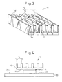
- Fig. 3 is a perspective view of the heat sink 10 in which a local deformation is caused by an external force
- Fig. 4 is a front view schematically showing one exemplary application of the heat sink 10.
- the heat sink 10 includes a base 12, and a plurality of upright heat-radiating projections 14 provided on the base 12.
- the heat-radiating projections 14 include a first projection 16 and a second projection 18, which have rigidities, different from each other, for maintaining their shape against external force.
- the second projections 18, having a rigidity lower than the rigidity of the first projections 16, is located along an outer periphery of an array or configuration of the plurality of heat-radiating projections 14 on the base 12.
- the base 12 is a rectangular flat-plate element, and is provided on one flat surface 12a thereof with the plurality of heat-radiating projections 14, each of which is a fin-shaped (or thin plate-like) element, and which project in an integral or unitary manner from the base 12 and are generally arranged parallel with each other at regular intervals.
- a plurality of (four, in the drawing) first projections 16, each having a rigidity higher than the rigidity of the second projection 18, are arranged near a center of the surface 12a of the base 12 and a plurality of (two, in the drawing) second projections 18, each having the rigidity lower than the rigidity of the first projections 16, are arranged along a pair of outer edges of the base surface 12a.
- the heat sink 10 is integrally or unitarily molded, in its entirety, from a metallic material having excellent heat conductivity.
- each first projection 16 with a relatively high rigidity has a first cross-sectional area S1 (or a first thickness T1) in a sectional plane generally parallel with the base surface 12a
- each second projection 18 with a relatively low rigidity has a second cross-sectional area S2 (or a second thickness T2) smaller than the first cross-sectional area S1 in a sectional plane generally parallel with the base surface 12a.
- the first projections 16 may keep their own shape while the second projections 18 are deformed.
- Fig. 3 shows, by way of example, a situation in which one of the second projections 18 has plastic deformation at a corner 18a of its extremity.
- the heat sink 10 is securely attached, on a back surface 12b of the base 12 thereof, to an electronic component (e.g., a microprocessor) 22 mounted on a surface 20a of a circuit board 20, directly through an adhesive layer 24 having excellent heat conductivity.
- an electronic component e.g., a microprocessor
- the heat sink 10 may be additionally provided with an electrically driven fan (not shown) for forcing air to flow between the heat-radiating projections 14 in order to improve cooling capacity.
- the second projection 18 located along the outer periphery of the array or configuration of the heat-radiating projections 14 on the base 12, is structured to have lower rigidity allowing the second projections 18 to be deformed by less external force, compared with the first projection 16.
- the heat-radiating projection 14 located along the outer periphery of the array or configuration of the heat-radiating projections 14 on the base 12 is, in particular, likely to receive unexpected external force, due to a collision with surrounding objects caused by, e.g., carelessness in manufacturing, transportation, storage, parts replacement, etc., of electric or electronic equipment.
- the heat sink 10 in which the heat-radiating projection 14, disposed at such a location as to be easily subjected to external force, is structured as the second projection 18 having relatively low rigidity it is possible, when external force is applied, to relieve the impact due to the external force by the deformation of the second projection 18, and thus to effectively prevent stress from concentrating on, and the resultant damage of, the electronic component 22. It should be noted that, even under the above circumstances, the first projections 16 having relatively high rigidity can maintain their shape against external force, and therefore, the heat-radiating function of the heat sink 10 is not significantly affected.
- the first projection 16 and the second projection 18, having rigidities different from each other in order to maintain their shape against external force are not limited to the configuration of the above-described embodiment, and other various configurations may be adopted.
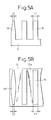
- the thickness of the second projection 18 may be gradually reduced toward its top end farthest from the base 12 (Fig. 5A), or may be gradually reduced toward opposite longitudinal ends along the base surface 12a (Fig. 5B).
- Figs. 6A and 6B in a configuration having fin-shaped heat-radiating projections 14 arranged in a plurality of separate rows (Fig. 6A), or in a configuration having a large number of pin-shaped heat-radiating projections 14 (Fig. 6B), it is possible ensure operative effects equivalent to those of the above-described embodiment by disposing the second projections 18 each having the rigidity lower than the rigidity of the first projection 16 (i.e., the second projections 18 each having the second cross-sectional area S2 smaller than the first cross-sectional area S1 of the first projection 16) along the outer periphery of the array or configuration of the plurality of heat-radiating projections 14 on the base 12. In any case, it is possible to reliably ensure the most preferable effect by optimizing the shape, dimension and position of the second projection 18 when the heat sink 10 is designed.
- the second projection 18 in place of the above-described configuration wherein the cross-sectional area S2 of the second projection 18 is smaller than the cross-sectional area S1 of the first projection 16, another configuration may also be adopted, wherein the second projection 18 includes a proximal end portion 26 made of a material identical to the material of the first projection 16 and joined to the base 12, and distal end portion 28 made of a material different from the material of the proximal end portion 26 and exhibiting rigidity lower than the rigidity of the first projection 16.
- the heat-radiating projection 14 located along the outer periphery of the array or configuration of the heat-radiating projections 14 on the base 12 may be structured as the second projection 18.
- the second projection 18 is provided with the proximal end portion 26 having a shape and dimension identical to that of each of the remaining first projections 16, and is structured by securely attaching the distal end portion 28 made of, e.g., silicone rubber, urethane rubber, soft resin, to a corner 26a of the extremity of the proximal end portion 26.
- the heat-radiating projection 14 located along the outer periphery of the array or configuration of the heat-radiating projections 14 on the base 12 may be structured in advance as the second projection 18, by molding the proximal end portion 26 having a shape different from that of the first projection 16 (for example, a shape having a chamfered portion 26b at the corner of its extremity) in a manner as to be integral or unitary with the base 12, and securely attaching the distal end portion 28 to the proximal end portion 26, so as to obtain a shape similar to that of the first projection 16.
- a shape different from that of the first projection 16 for example, a shape having a chamfered portion 26b at the corner of its extremity
- the heat-radiating projection 14, disposed at such a location as to be easily subjected to unexpected external force is structured as the second projection 18 including the distal end portion 28 having relatively low rigidity, it is possible, when external force is applied, to relieve impact due to external force by the deformation of the distal end portion 28 of the second projection 18, and thus to effectively prevent stress from concentrating on, and the resultant damage of, the electronic component 22.
- the material of the distal end portion 28 is selected so that the distal end portion 28 has plastic deformation by external force, reliable evidence of the applied external force remains, and therefore, when the electric or electronic equipment is inspected or an investigation is made after a malfunction, it is possible to easily determine the cause of malfunction and the damaged portion.
- the distal end portion 28 capable of exhibiting a sufficiently impact-relieving function, for the heat-radiating projection 14 located at a position where it is highly anticipated that external force may be applied to the projection, by a posterior attaching work as occasion demands, and therefore, there is an advantage that the heat sink 10 can be made more versatile.
- the distal end portion 28 of the second projection 18 is made of a material that is not only adapted to be deformed (preferably, plastically deformed) relatively easily by external force, but also has excellent heat-resistance and heat-radiating properties.
- the configuration of the second projection 18 structured by two types of elements may be additionally applied to the second projection 18 having a cross-sectional area smaller than that of the first projection 16 as already described.
Landscapes
- Cooling Or The Like Of Semiconductors Or Solid State Devices (AREA)
- Cooling Or The Like Of Electrical Apparatus (AREA)
- Professional, Industrial, Or Sporting Protective Garments (AREA)
Applications Claiming Priority (1)
| Application Number | Priority Date | Filing Date | Title |
|---|---|---|---|
| JP2006182004A JP2008010761A (ja) | 2006-06-30 | 2006-06-30 | 電子部品のヒートシンク |
Publications (2)
| Publication Number | Publication Date |
|---|---|
| EP1873828A2 true EP1873828A2 (fr) | 2008-01-02 |
| EP1873828A3 EP1873828A3 (fr) | 2008-10-22 |
Family
ID=38421595
Family Applications (1)
| Application Number | Title | Priority Date | Filing Date |
|---|---|---|---|
| EP07012596A Withdrawn EP1873828A3 (fr) | 2006-06-30 | 2007-06-27 | Dissipateur de chaleur pour composant électronique |
Country Status (4)
| Country | Link |
|---|---|
| US (1) | US20080013279A1 (fr) |
| EP (1) | EP1873828A3 (fr) |
| JP (1) | JP2008010761A (fr) |
| CN (1) | CN101098614A (fr) |
Cited By (1)
| Publication number | Priority date | Publication date | Assignee | Title |
|---|---|---|---|---|
| EP2284884A3 (fr) * | 2009-08-12 | 2011-04-20 | SEMIKRON Elektronik GmbH & Co. KG | Agencement doté d'un dispositif de refroidissement et d'un module semi-conducteur de puissance |
Families Citing this family (5)
| Publication number | Priority date | Publication date | Assignee | Title |
|---|---|---|---|---|
| US8652040B2 (en) * | 2006-12-19 | 2014-02-18 | Valencell, Inc. | Telemetric apparatus for health and environmental monitoring |
| JP2012119671A (ja) * | 2010-11-11 | 2012-06-21 | Kitagawa Ind Co Ltd | 電子回路及びヒートシンク |
| JP5502805B2 (ja) * | 2011-06-08 | 2014-05-28 | 日立オートモティブシステムズ株式会社 | パワーモジュールおよびそれを用いた電力変換装置 |
| CN107613171B (zh) * | 2017-09-26 | 2020-07-24 | Oppo广东移动通信有限公司 | 摄像头模组和移动终端 |
| JP7119928B2 (ja) * | 2018-11-12 | 2022-08-17 | トヨタ自動車株式会社 | 制御ユニット |
Family Cites Families (16)
| Publication number | Priority date | Publication date | Assignee | Title |
|---|---|---|---|---|
| US4823869A (en) * | 1986-06-19 | 1989-04-25 | International Business Machines Corporation | Heat sink |
| US4715438A (en) * | 1986-06-30 | 1987-12-29 | Unisys Corporation | Staggered radial-fin heat sink device for integrated circuit package |
| JPH02276264A (ja) * | 1989-04-18 | 1990-11-13 | Nec Corp | ヒートシンク付セラミックパッケージ |
| US5455382A (en) * | 1991-10-31 | 1995-10-03 | Sumitomo Metal Industries, Ltd. | IC package heat sink fin |
| US5597034A (en) * | 1994-07-01 | 1997-01-28 | Digital Equipment Corporation | High performance fan heatsink assembly |
| JPH09129790A (ja) * | 1995-11-07 | 1997-05-16 | Toshiba Corp | ヒートシンク装置 |
| US6009937A (en) * | 1995-12-20 | 2000-01-04 | Hoogovens Aluminium Profiltechnik Gmbh | Cooling device for electrical or electronic components having a base plate and cooling elements and method for manufacturing the same |
| TW349193B (en) * | 1997-11-14 | 1999-01-01 | Hon Hai Prec Ind Co Ltd | Method of assembling heat sink fins and product thereof |
| TW376171U (en) * | 1998-11-24 | 1999-12-01 | Foxconn Prec Components Co Ltd | Radiating device |
| JP2000174186A (ja) * | 1998-12-08 | 2000-06-23 | Hitachi Ltd | 半導体装置およびその実装方法 |
| JP2001267477A (ja) * | 2000-03-22 | 2001-09-28 | Yukifumi Nakano | 放熱用フィン及びその実装方法 |
| JP3529358B2 (ja) * | 2001-02-07 | 2004-05-24 | 古河電気工業株式会社 | フィン付ヒートシンク |
| US6862183B2 (en) * | 2001-10-29 | 2005-03-01 | Intel Corporation | Composite fins for heat sinks |
| US6707676B1 (en) * | 2002-08-30 | 2004-03-16 | Ehood Geva | Heat sink for automatic assembling |
| US6845812B2 (en) * | 2002-12-20 | 2005-01-25 | Motorola, Inc. | Heatsink with multiple, selectable fin densities |
| CN2672865Y (zh) * | 2003-11-14 | 2005-01-19 | 鸿富锦精密工业(深圳)有限公司 | 散热器 |
-
2006
- 2006-06-30 JP JP2006182004A patent/JP2008010761A/ja active Pending
-
2007
- 2007-06-26 US US11/768,573 patent/US20080013279A1/en not_active Abandoned
- 2007-06-27 EP EP07012596A patent/EP1873828A3/fr not_active Withdrawn
- 2007-06-29 CN CN200710126869.0A patent/CN101098614A/zh active Pending
Cited By (1)
| Publication number | Priority date | Publication date | Assignee | Title |
|---|---|---|---|---|
| EP2284884A3 (fr) * | 2009-08-12 | 2011-04-20 | SEMIKRON Elektronik GmbH & Co. KG | Agencement doté d'un dispositif de refroidissement et d'un module semi-conducteur de puissance |
Also Published As
| Publication number | Publication date |
|---|---|
| US20080013279A1 (en) | 2008-01-17 |
| JP2008010761A (ja) | 2008-01-17 |
| EP1873828A3 (fr) | 2008-10-22 |
| CN101098614A (zh) | 2008-01-02 |
Similar Documents
| Publication | Publication Date | Title |
|---|---|---|
| JP5223212B2 (ja) | ヒートシンクを備える電子部品の実装構造 | |
| US6474407B1 (en) | Composite heat sink with high density fins and assembling method for the same | |
| US4751199A (en) | Process of forming a compliant lead frame for array-type semiconductor packages | |
| US20080013279A1 (en) | Heat sink for electronic component | |
| US7755895B2 (en) | Heat sink, an electronic component package, and a method of manufacturing a heat sink | |
| CN105580134B (zh) | 铆接散热器、散热器一体型功率模块、及它们的制造方法 | |
| CN101005054A (zh) | 存储器模块冷却体 | |
| US7564687B2 (en) | Heat dissipation device having a fixing base | |
| US20180252483A1 (en) | Heatsink stiffener method and apparatus | |
| US7161238B2 (en) | Structural reinforcement for electronic substrate | |
| US8362610B2 (en) | Mounting configuration of electronic component | |
| US20140285973A1 (en) | Housing and power module having the same | |
| US20190252292A1 (en) | Power module and semiconductor apparatus | |
| US10123441B2 (en) | Memory device with daughter board fastening structure | |
| US8485698B2 (en) | Heat pipe, heat dissipating module and illumination device | |
| JP2001119107A (ja) | プリント配線板 | |
| US8970030B2 (en) | Electronic assembly and method for producing same | |
| EP1037518A2 (fr) | Radiateur pour une plaquette de circuit | |
| KR20160097584A (ko) | 실장 기판 모듈 및 실장 기판 모듈 제조 방법 | |
| JP7143096B2 (ja) | 回路モジュール | |
| EP3712936B1 (fr) | Conception de base flexible pour dissipateur de chaleur de jeu de puces | |
| JP3813120B2 (ja) | 半導体装置の実装体 | |
| CN101335316B (zh) | 具有散热销的发光二极管封装体及其制造方法 | |
| LU506715B1 (en) | Heat Spreader, Electronic Module, Electronic Assembly, Method for Manufacturing an Electronic Module, and Method for Manufacturing an Electronic Assembly | |
| JP3631193B2 (ja) | 放熱装置 |
Legal Events
| Date | Code | Title | Description |
|---|---|---|---|
| PUAI | Public reference made under article 153(3) epc to a published international application that has entered the european phase |
Free format text: ORIGINAL CODE: 0009012 |
|
| AK | Designated contracting states |
Kind code of ref document: A2 Designated state(s): AT BE BG CH CY CZ DE DK EE ES FI FR GB GR HU IE IS IT LI LT LU LV MC MT NL PL PT RO SE SI SK TR |
|
| AX | Request for extension of the european patent |
Extension state: AL BA HR MK YU |
|
| PUAL | Search report despatched |
Free format text: ORIGINAL CODE: 0009013 |
|
| STAA | Information on the status of an ep patent application or granted ep patent |
Free format text: STATUS: THE APPLICATION HAS BEEN WITHDRAWN |
|
| 18W | Application withdrawn |
Effective date: 20080905 |
|
| AK | Designated contracting states |
Kind code of ref document: A3 Designated state(s): AT BE BG CH CY CZ DE DK EE ES FI FR GB GR HU IE IS IT LI LT LU LV MC MT NL PL PT RO SE SI SK TR |
|
| AX | Request for extension of the european patent |
Extension state: AL BA HR MK RS |
|
| R18W | Application withdrawn (corrected) |
Effective date: 20080905 |