EP1873873A2 - Elektrische Anschlussvorrichtung mit schneller Montage und deren Verwendung zur Neutralisierung einer überschüssigen Hochspannungsausgangsklemme eines elektronischen Gasanzünders für elektrische Haushaltsgeräte, im Besonderen eines Küchenherdes - Google Patents
Elektrische Anschlussvorrichtung mit schneller Montage und deren Verwendung zur Neutralisierung einer überschüssigen Hochspannungsausgangsklemme eines elektronischen Gasanzünders für elektrische Haushaltsgeräte, im Besonderen eines Küchenherdes Download PDFInfo
- Publication number
- EP1873873A2 EP1873873A2 EP07111482A EP07111482A EP1873873A2 EP 1873873 A2 EP1873873 A2 EP 1873873A2 EP 07111482 A EP07111482 A EP 07111482A EP 07111482 A EP07111482 A EP 07111482A EP 1873873 A2 EP1873873 A2 EP 1873873A2
- Authority
- EP
- European Patent Office
- Prior art keywords
- gas lighter
- assembly portion
- electric
- cantilevered
- contact
- Prior art date
- Legal status (The legal status is an assumption and is not a legal conclusion. Google has not performed a legal analysis and makes no representation as to the accuracy of the status listed.)
- Granted
Links
Images
Classifications
-
- H—ELECTRICITY
- H01—ELECTRIC ELEMENTS
- H01R—ELECTRICALLY-CONDUCTIVE CONNECTIONS; STRUCTURAL ASSOCIATIONS OF A PLURALITY OF MUTUALLY-INSULATED ELECTRICAL CONNECTING ELEMENTS; COUPLING DEVICES; CURRENT COLLECTORS
- H01R31/00—Coupling parts supported only by co-operation with counterpart
- H01R31/08—Short-circuiting members for bridging contacts in a counterpart
-
- F—MECHANICAL ENGINEERING; LIGHTING; HEATING; WEAPONS; BLASTING
- F23—COMBUSTION APPARATUS; COMBUSTION PROCESSES
- F23Q—IGNITION; EXTINGUISHING-DEVICES
- F23Q3/00—Igniters using electrically-produced sparks
-
- H—ELECTRICITY
- H01—ELECTRIC ELEMENTS
- H01R—ELECTRICALLY-CONDUCTIVE CONNECTIONS; STRUCTURAL ASSOCIATIONS OF A PLURALITY OF MUTUALLY-INSULATED ELECTRICAL CONNECTING ELEMENTS; COUPLING DEVICES; CURRENT COLLECTORS
- H01R13/00—Details of coupling devices of the kinds covered by groups H01R12/70 or H01R24/00 - H01R33/00
- H01R13/648—Protective earth or shield arrangements on coupling devices, e.g. anti-static shielding
- H01R13/652—Protective earth or shield arrangements on coupling devices, e.g. anti-static shielding with earth pin, blade or socket
Definitions
- the present invention relates to a fast-fit electric connecting device intended to be coupled to a terminal, in particular a high-voltage output terminal, of an electronic gas lighter device for an electric household appliance; and to the use thereof for neutralizing a surplus high-voltage output terminal exceeding the number of terminals needed by the aforesaid gas lighter device by electrically grounding the surplus terminal, in particular for electrically connecting the surplus terminal to an electric conducting element of the electric household appliance, typically a cooking range, against which the gas lighter device is intended to be integrally fastened in use, by means of screws and/or by snap-fitting.
- a drawback of the above-described solution therefore consists in that the assembler of the cooking range must use an additional grounding wire (as well as the grounding wire prescribed by the specifications for the device as a whole, possibly replaced by the U-spring according to EP 1101066B1 ), with consequent increased costs, times and assembly difficulties (the operation is normally performed in restricted spaces).
- the present invention thus relates to a device of the aforesaid type, as defined in claim 1.
- the device according to the invention is used, according to an aspect of the invention, to neutralize, by means of grounding through the electric connection to the mentioned electric conducting element of the electric household appliance, of a high-voltage output terminal of the gas lighter device exceeding the number of high-voltage output terminals needed by the electric household appliance itself.
- the device according to the invention consists in an elastically deformable metallic foil, comprising: a U-shaped assembly portion, adapted to be inserted in a contact carrier stack of an electrically non-conducting casing of the gas lighter device; and a working portion defined by an arm, which extends askew and cantilevered from a first end of the assembly portion and which is shaped so as to be adapted, in use, to extend in cantilevered manner out of the contact carrier stack and distanced from the casing to cooperate in contact against the electrically conducting element.
- the assembly portion is then provided with a slot for the mechanical and electrical coupling with a respective blade contact (to be neutralized) accommodated within the contact carrier stack of the casing of the gas lighter device and with a second end, opposite to the first, and adapted to engage in use an internal side wall of the contact carrier stack, consequent to an elastic deformation of the foil consequent to the reciprocal contact between the cantilevered arm of the working portion and the electrically conducting element of the electric household appliance.
- the contact device formed of the foil onto the high-voltage terminal to be neutralized (e.g. the sixth terminal of a gas lighter device intended to equip a cooking range having only five burners) simply by inserting the assembly portion in the respective contact carrier stack corresponding to the terminal to be neutralized, which is engaged in the slot of the foil, thus leaving the arm askew and laterally cantilevered, transversally with respect to a longitudinal axis of the gas lighter device, out of the stack and so as to be distanced in a cantilevered manner from the casing of the gas lighter device, askew with respect to the aforesaid axis of symmetry of the gas lighter device and towards the conducting element formed by the cooking range.
- the contact device formed of the foil onto the high-voltage terminal to be neutralized (e.g. the sixth terminal of a gas lighter device intended to equip a cooking range having only five burners) simply by inserting the assembly portion in the respective contact carrier stack corresponding to the terminal to be neutralized, which is engaged in the slot of the foil
- the aforesaid arm extends askew and cantilevered from the stack of the terminal to be neutralized with respect to the casing, and in direction so as to be distanced from the casing itself, is pressed against the cooking range with at least its free end by interference coupling, because it protrudes from the casing of the gas lighter device towards the cooking range more than the clearance normally present in use, after assembly, between casing of the gas lighter device and surface of the cooking range of other conducting element of the electric household appliance to which the gas lighter device is fixed in use (e.g. to the part of the armature of the household appliance).
- the askew and cantilevered arm of the working portion of the connection device according to the invention elastically bends, thus leading the coupling portion of the stack to possibly turn (in the presence of sufficient clearance), on the terminal to be neutralized (which serves as a hinge), taking the end of the assembly portion opposite to the cantilevered arm and provided with specific teeth, to be driven into the relatively soft synthetic plastic material, forming the side wall of the stack, thus ensuring the impossibility of accidental removal of the foil of the fast-fit connecting device according to the invention from the stack itself (and the relative high-voltage terminal).
- the surplus high-voltage terminal is actually naturalized in permanent, simple and rapid manner, without the use of grounding wires and without the need to internally modify the gas lighter device.
- numeral 1 indicates as a whole a device for the fast-fit electrical connection of a high-voltage output terminal 2 of an electronic gas lighter device 3 (of known type, e.g. from EP 1101066B1 , and which is thus not further described in detail for the sake of simplicity) to an electrically conducting element 4 of an electric household appliance (known and not shown for the sake of simplicity) against which the gas lighter device 3 is intended in use to be integrally fixed, e.g. to a lower surface of a cooking range equipped with a certain number of burners, known and not shown, or a part of the carcass of the electric household appliance.
- an electronic gas lighter device 3 of known type, e.g. from EP 1101066B1 , and which is thus not further described in detail for the sake of simplicity
- an electric household appliance known and not shown for the sake of simplicity
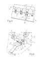
- Electrically conducting element 4 is normally connected (in known manner and not shown for the sake of simplicity) to a reference potential, i.e. it is electrically "grounded", e.g. by means of part of the electric circuit within device 3 itself and, as shown below, device 1 is used according to the invention (figures 4 and 5) to neutralize the ground connection (by means of element 4) of an output terminal 2b (figure 5) exceeding the number of high-voltage output terminals 2 of gas lighter device 3 needed by the household appliance, e.g. exceeding the number of burners of the cooking range forming conducting element 4 (in general).
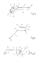
- electric connecting device 1 consists of a simple elastically deformable metallic foil, particularly shaped by folding over the elastic limit, so as to comprise a U-shaped assembly portion 10, adapted to be inserted in use in a contact carrier stack 11 (figure 5) of an electrically non-conducting casing 12 (e.g. formed by an injection moulded synthetic plastic material) of the gas lighter device 3; and furthermore so as to comprise a working portion defined by an arm 14, which extends askew and cantilevered from a first end 15 of assembly portion 10 and which is shaped so as to be adapted, in use, to cooperate in contact against electrically conducting element 4 (figure 4).
- a simple elastically deformable metallic foil particularly shaped by folding over the elastic limit, so as to comprise a U-shaped assembly portion 10, adapted to be inserted in use in a contact carrier stack 11 (figure 5) of an electrically non-conducting casing 12 (e.g. formed by an injection moulded synthetic plastic material) of the gas lighter device 3; and furthermore
- Assembly portion 10 is provided with a slot 16 for the mechanical and electrical coupling with respective terminal 2b of the blade type accommodated within contact carrier stack 11 of casing 12, and a second end 18, opposite to end 15, adapted to engage in use to engage an internal side wall 21 of contact carrier stack 11, also consequent to an elastic deformation of foil 1 consequent to the reciprocal contact in use between cantilevered arm 14 and electrically conducting element 4 of the electric household appliance.
- assembly portion 10 is asymmetrically U-shaped, where first end 15 forms a side branch having longer length than the asymmetric U and second end 18 forms an opposite side branch, having a shorter length than the asymmetric U.
- slot 16 is made through an intermediate connection segment 22 of the U between the longer and the shorter length side branches formed by ends 15 and 18, and is transversally oriented with respect to cantilevered arm 14 forming the working portion, displaying (figure 1) a longitudinal direction of extension (length) oriented perpendicularly with respect to a longitudinal direction of extension (length) of cantilevered arm 14, identifiable in figure 2 with a perpendicular to the plane of the sheet and with the plane of the sheet, respectively.
- slot 16 displays dimensions such as to couple in use with a predetermined clearance with blade terminal 2b to be neutralized of gas lighter device 3; such predetermined clearance is specifically of an order such that elastically formable foil 1 may oscillate in use on blade terminal 2b to which it is coupled within contact carrier stack 11 so as to press second end 18 against side wall 21 of stack 11; for the same purpose, assembly portion 10 is also preferably shaped so as to be coupled with a slight predetermined clearance within stack 11. In this manner, a very high assembly ease of device 1 on gas lighter device 3 is obtained, also in the presence of relatively high machining tolerances without, on the other hand, the risk of leading the electrical connection of terminal 2b with element 4 through blade 1 to fail, as shown below.
- Second end 18 is preferably provided with at least one anchoring tooth 30, even more preferably with a pair of anchoring teeth 30 side by side, for anchoring side wall 21, essentially isosceles-triangle-shaped, adapted to be driven into side wall 21 of contact carrier stack 11 of casing 12 in virtue of the fact that the latter, as the entire casing 12, are formed by relatively soft synthetic plastic material with respect to the metallic material with which elastically deformable foil 1 forming the fast-fit electric connection device of the invention is made, typically steel (or other alloy, e.g. even brass) of the harmonic type.
- Anchoring tooth 30 or pair of teeth 30 to wall 21 is/are cantilevered at an end edge 32 of second end 18 of assembly portion 10, which edge 32 (figure 3) was folded askew (with respect to the branch of the U defined by end 18 itself) on opposite side to the skew and cantilevered direction of extension of opposite arm 14 defined by end 15.
- Cantilevered skew arm 14 is in turn provided with a free end 40 folded so as to be essentially parallel to respective side branches of U-shaped assembly portion 10 when metallic foil 1 is in undeformed conditions (figure 3).
- fast-fit electric connecting device 1 in figures 1-3 described herein is used in an innovative manner according to the invention to effectively neutralize a high-voltage output terminal 2b of electronic gas lighter device 3 exceeding the number of high-voltage output terminals 2 needed by the electric household appliance, by grounding terminal 2b (surplus with respect to the total number of existing terminals 2) with electrically conducting element 4 of the electric household appliance, against which gas lighter device 3 is however intended to be integrally fixed in use.
- elastically deformable foil 1 is integrally mounted onto gas lighter device 3 with its assembly portion 10 inserted against contact carrier stack 11 of casing 12 corresponding to surplus terminal 2b and throughly accommodating the same; furthermore, slot 16 is, in such configuration, mechanically and electrically connected to surplus terminal 2b, which is throughly inserted across the same in assembly portion 10.
- arm 14 is arranged askew and cantilevered from contact carrier stack 11 accommodating terminal 2b and extends laterally cantilevered, transversally with respect to a longitudinal axis A of gas lighter device 3 and out of stack 11, so as to be distanced in cantilevered manner from casing 12 askew with respect to aforesaid axis A and towards conducting element 4.
- the use of the invention provides for the fixing in a known manner (besides necessary in any case) of gas lighter device 3 to electrically conducting element 4, performed so that arm 14 is pressed, at least with its free end 40, against electrically conducting element 4 with a force such as to press for example by elastic reaction and/or by oscillation of foil 1 on terminal 2b and in stack 11, second end 18 of assembly portion 10 (in particular edge 32 with teeth 30) against side wall 21 of stack 11.
Landscapes
- Engineering & Computer Science (AREA)
- Chemical & Material Sciences (AREA)
- Combustion & Propulsion (AREA)
- Mechanical Engineering (AREA)
- General Engineering & Computer Science (AREA)
- Lighters Containing Fuel (AREA)
- Details Of Connecting Devices For Male And Female Coupling (AREA)
- Control Of Resistance Heating (AREA)
- Cookers (AREA)
Priority Applications (1)
| Application Number | Priority Date | Filing Date | Title |
|---|---|---|---|
| PL07111482T PL1873873T3 (pl) | 2006-06-30 | 2007-06-29 | Szybkozłączne urządzenie połączeniowe i jego zastosowanie do zerowania nadmiarowego wysokonapięciowego zacisku wyjściowego elektronicznej zapalniczki do gazu w elektrycznych urządzenia gospodarstwa domowego, zwłaszcza w kuchence |
Applications Claiming Priority (1)
| Application Number | Priority Date | Filing Date | Title |
|---|---|---|---|
| IT000484A ITTO20060484A1 (it) | 2006-06-30 | 2006-06-30 | Dispositivo di connessione elettrica a montaggio rapido e suo uso per la neutralizzazione di un terminale di uscita in alta tensione eccedente in un dispositivo accendigas elettronico per elettrodomestici, in particolare per un piano di cottura |
Publications (3)
| Publication Number | Publication Date |
|---|---|
| EP1873873A2 true EP1873873A2 (de) | 2008-01-02 |
| EP1873873A3 EP1873873A3 (de) | 2010-01-06 |
| EP1873873B1 EP1873873B1 (de) | 2012-04-11 |
Family
ID=38512419
Family Applications (1)
| Application Number | Title | Priority Date | Filing Date |
|---|---|---|---|
| EP07111482A Active EP1873873B1 (de) | 2006-06-30 | 2007-06-29 | Elektrische Anschlussvorrichtung mit schneller Montage und deren Verwendung zur Neutralisierung einer überschüssigen Hochspannungsausgangsklemme eines elektronischen Gasanzünders für elektrische Haushaltsgeräte, im Besonderen eines Küchenherdes |
Country Status (4)
| Country | Link |
|---|---|
| EP (1) | EP1873873B1 (de) |
| ES (1) | ES2384647T3 (de) |
| IT (1) | ITTO20060484A1 (de) |
| PL (1) | PL1873873T3 (de) |
Cited By (1)
| Publication number | Priority date | Publication date | Assignee | Title |
|---|---|---|---|---|
| EP2149754A3 (de) * | 2008-07-22 | 2011-07-13 | BSH Bosch und Siemens Hausgeräte GmbH | Hausgerätvorrichtung |
Family Cites Families (4)
| Publication number | Priority date | Publication date | Assignee | Title |
|---|---|---|---|---|
| WO1984003180A1 (en) * | 1983-02-02 | 1984-08-16 | Apex Eng Corp | Bus clip |
| IT245884Y1 (it) * | 1998-07-28 | 2002-03-26 | Miller Europe Spa | Dispositivo elettronico su piastra, in particolare accendigaselettronico, includente mezzi collegamento rapido tra fili |
| IT1303088B1 (it) * | 1998-07-28 | 2000-10-30 | Miller Europe Spa | Dispositivo accendigas elettronico ad attacco rapido. |
| ITTO20030278A1 (it) * | 2003-04-11 | 2004-10-12 | Itw Ind Components Srl | Dispositivo accendigas elettrico realizzabile senza vincoli nel numero di terminali di uscita e metodo per la sua fabbricazione. |
-
2006
- 2006-06-30 IT IT000484A patent/ITTO20060484A1/it unknown
-
2007
- 2007-06-29 PL PL07111482T patent/PL1873873T3/pl unknown
- 2007-06-29 ES ES07111482T patent/ES2384647T3/es active Active
- 2007-06-29 EP EP07111482A patent/EP1873873B1/de active Active
Cited By (1)
| Publication number | Priority date | Publication date | Assignee | Title |
|---|---|---|---|---|
| EP2149754A3 (de) * | 2008-07-22 | 2011-07-13 | BSH Bosch und Siemens Hausgeräte GmbH | Hausgerätvorrichtung |
Also Published As
| Publication number | Publication date |
|---|---|
| ITTO20060484A1 (it) | 2008-01-01 |
| PL1873873T3 (pl) | 2012-09-28 |
| EP1873873B1 (de) | 2012-04-11 |
| ES2384647T3 (es) | 2012-07-10 |
| EP1873873A3 (de) | 2010-01-06 |
Similar Documents
| Publication | Publication Date | Title |
|---|---|---|
| EP2048746B1 (de) | Stromschienenanschlusssystem | |
| EP2690713B1 (de) | Leiter-zu-platine-steckverbinder | |
| US5700159A (en) | Electrical connection element | |
| US7083463B2 (en) | Electrical supply or connecting terminal | |
| US9209578B2 (en) | Connecting structure for electronic devices | |
| JP2011222509A (ja) | 電気接続端子用操作装置 | |
| JP6580677B2 (ja) | 電気コネクタ用端子 | |
| CN105765219A (zh) | 驱动装置及其安装结构 | |
| US4793059A (en) | Automatic grounding clip | |
| CN108604743B (zh) | 电气的插接接触件 | |
| EP1873873B1 (de) | Elektrische Anschlussvorrichtung mit schneller Montage und deren Verwendung zur Neutralisierung einer überschüssigen Hochspannungsausgangsklemme eines elektronischen Gasanzünders für elektrische Haushaltsgeräte, im Besonderen eines Küchenherdes | |
| CN101170016A (zh) | 设备开关装置以及用于设备开关装置的连接端子 | |
| FI68930C (fi) | Elektrisk stickanslutning | |
| US20080102714A1 (en) | Service switching device and connection terminal for a service switching device | |
| US6215080B1 (en) | Switch device with AC inlet and AC switch | |
| CN103222115A (zh) | 电子器件的连接结构 | |
| US4745523A (en) | Automatic grounding clip | |
| CN215379685U (zh) | 具有屏蔽片的插式连接器组件 | |
| KR100842725B1 (ko) | 내진동 커넥터 | |
| EP2082455B1 (de) | Zum passen in ein terminal-board ausgelegter schnelllösekontakt, insbesondere für eine elektronische gaszündeinrichtung für elektrische haushaltsgeräte | |
| CN221596944U (zh) | 一种直插自锁端子 | |
| CN115244782B (zh) | 连接装置以及组件和电子设备 | |
| WO2013133348A2 (en) | Connection structure of electronic components | |
| KR101579480B1 (ko) | 특히 가전 기기를 위한 일체형 접지 접점을 갖는 케이블 클램프 홀더 | |
| GB2414602A (en) | Spring connector for electric motor |
Legal Events
| Date | Code | Title | Description |
|---|---|---|---|
| PUAI | Public reference made under article 153(3) epc to a published international application that has entered the european phase |
Free format text: ORIGINAL CODE: 0009012 |
|
| AK | Designated contracting states |
Kind code of ref document: A2 Designated state(s): AT BE BG CH CY CZ DE DK EE ES FI FR GB GR HU IE IS IT LI LT LU LV MC MT NL PL PT RO SE SI SK TR |
|
| AX | Request for extension of the european patent |
Extension state: AL BA HR MK YU |
|
| PUAL | Search report despatched |
Free format text: ORIGINAL CODE: 0009013 |
|
| AK | Designated contracting states |
Kind code of ref document: A3 Designated state(s): AT BE BG CH CY CZ DE DK EE ES FI FR GB GR HU IE IS IT LI LT LU LV MC MT NL PL PT RO SE SI SK TR |
|
| AX | Request for extension of the european patent |
Extension state: AL BA HR MK RS |
|
| RIC1 | Information provided on ipc code assigned before grant |
Ipc: H01R 31/08 20060101AFI20070926BHEP Ipc: F23Q 3/00 20060101ALI20091127BHEP Ipc: H01R 13/652 20060101ALI20091127BHEP |
|
| 17P | Request for examination filed |
Effective date: 20100705 |
|
| AKX | Designation fees paid |
Designated state(s): ES IT PL TR |
|
| REG | Reference to a national code |
Ref country code: DE Ref legal event code: 8566 |
|
| GRAP | Despatch of communication of intention to grant a patent |
Free format text: ORIGINAL CODE: EPIDOSNIGR1 |
|
| GRAS | Grant fee paid |
Free format text: ORIGINAL CODE: EPIDOSNIGR3 |
|
| GRAA | (expected) grant |
Free format text: ORIGINAL CODE: 0009210 |
|
| AK | Designated contracting states |
Kind code of ref document: B1 Designated state(s): ES IT PL TR |
|
| REG | Reference to a national code |
Ref country code: ES Ref legal event code: FG2A Ref document number: 2384647 Country of ref document: ES Kind code of ref document: T3 Effective date: 20120710 |
|
| REG | Reference to a national code |
Ref country code: PL Ref legal event code: T3 |
|
| PLBE | No opposition filed within time limit |
Free format text: ORIGINAL CODE: 0009261 |
|
| STAA | Information on the status of an ep patent application or granted ep patent |
Free format text: STATUS: NO OPPOSITION FILED WITHIN TIME LIMIT |
|
| 26N | No opposition filed |
Effective date: 20130114 |
|
| PGFP | Annual fee paid to national office [announced via postgrant information from national office to epo] |
Ref country code: IT Payment date: 20180621 Year of fee payment: 12 |
|
| PG25 | Lapsed in a contracting state [announced via postgrant information from national office to epo] |
Ref country code: IT Free format text: LAPSE BECAUSE OF NON-PAYMENT OF DUE FEES Effective date: 20190629 |
|
| P01 | Opt-out of the competence of the unified patent court (upc) registered |
Effective date: 20231101 |
|
| PGFP | Annual fee paid to national office [announced via postgrant information from national office to epo] |
Ref country code: PL Payment date: 20240604 Year of fee payment: 18 |
|
| PGFP | Annual fee paid to national office [announced via postgrant information from national office to epo] |
Ref country code: TR Payment date: 20240604 Year of fee payment: 18 |
|
| PGFP | Annual fee paid to national office [announced via postgrant information from national office to epo] |
Ref country code: ES Payment date: 20240701 Year of fee payment: 18 |