EP1874027A1 - Bilderzeugungsvorrichtung - Google Patents
Bilderzeugungsvorrichtung Download PDFInfo
- Publication number
- EP1874027A1 EP1874027A1 EP07110830A EP07110830A EP1874027A1 EP 1874027 A1 EP1874027 A1 EP 1874027A1 EP 07110830 A EP07110830 A EP 07110830A EP 07110830 A EP07110830 A EP 07110830A EP 1874027 A1 EP1874027 A1 EP 1874027A1
- Authority
- EP
- European Patent Office
- Prior art keywords
- screen
- setting
- operation screen
- user
- setting data
- Prior art date
- Legal status (The legal status is an assumption and is not a legal conclusion. Google has not performed a legal analysis and makes no representation as to the accuracy of the status listed.)
- Granted
Links
Images





Classifications
-
- H—ELECTRICITY
- H04—ELECTRIC COMMUNICATION TECHNIQUE
- H04N—PICTORIAL COMMUNICATION, e.g. TELEVISION
- H04N1/00—Scanning, transmission or reproduction of documents or the like, e.g. facsimile transmission; Details thereof
- H04N1/0035—User-machine interface; Control console
- H04N1/00405—Output means
- H04N1/00408—Display of information to the user, e.g. menus
- H04N1/00413—Display of information to the user, e.g. menus using menus, i.e. presenting the user with a plurality of selectable options
- H04N1/00416—Multi-level menus
-
- H—ELECTRICITY
- H04—ELECTRIC COMMUNICATION TECHNIQUE
- H04N—PICTORIAL COMMUNICATION, e.g. TELEVISION
- H04N1/00—Scanning, transmission or reproduction of documents or the like, e.g. facsimile transmission; Details thereof
- H04N1/0035—User-machine interface; Control console
- H04N1/00405—Output means
- H04N1/00408—Display of information to the user, e.g. menus
- H04N1/00413—Display of information to the user, e.g. menus using menus, i.e. presenting the user with a plurality of selectable options
-
- H—ELECTRICITY
- H04—ELECTRIC COMMUNICATION TECHNIQUE
- H04N—PICTORIAL COMMUNICATION, e.g. TELEVISION
- H04N1/00—Scanning, transmission or reproduction of documents or the like, e.g. facsimile transmission; Details thereof
- H04N1/0035—User-machine interface; Control console
- H04N1/00405—Output means
- H04N1/00408—Display of information to the user, e.g. menus
- H04N1/00413—Display of information to the user, e.g. menus using menus, i.e. presenting the user with a plurality of selectable options
- H04N1/00416—Multi-level menus
- H04N1/00419—Arrangements for navigating between pages or parts of the menu
- H04N1/00432—Arrangements for navigating between pages or parts of the menu using tabs
-
- H—ELECTRICITY
- H04—ELECTRIC COMMUNICATION TECHNIQUE
- H04N—PICTORIAL COMMUNICATION, e.g. TELEVISION
- H04N1/00—Scanning, transmission or reproduction of documents or the like, e.g. facsimile transmission; Details thereof
- H04N1/0035—User-machine interface; Control console
- H04N1/00405—Output means
- H04N1/00408—Display of information to the user, e.g. menus
- H04N1/00472—Display of information to the user, e.g. menus using a pop-up window
-
- H—ELECTRICITY
- H04—ELECTRIC COMMUNICATION TECHNIQUE
- H04N—PICTORIAL COMMUNICATION, e.g. TELEVISION
- H04N1/00—Scanning, transmission or reproduction of documents or the like, e.g. facsimile transmission; Details thereof
- H04N1/0035—User-machine interface; Control console
- H04N1/00405—Output means
- H04N1/00482—Output means outputting a plurality of job set-up options, e.g. number of copies, paper size or resolution
-
- H—ELECTRICITY
- H04—ELECTRIC COMMUNICATION TECHNIQUE
- H04N—PICTORIAL COMMUNICATION, e.g. TELEVISION
- H04N1/00—Scanning, transmission or reproduction of documents or the like, e.g. facsimile transmission; Details thereof
- H04N1/0035—User-machine interface; Control console
- H04N1/00501—Tailoring a user interface [UI] to specific requirements
- H04N1/00509—Personalising for a particular user or group of users, e.g. a workgroup or company
-
- H—ELECTRICITY
- H04—ELECTRIC COMMUNICATION TECHNIQUE
- H04N—PICTORIAL COMMUNICATION, e.g. TELEVISION
- H04N1/00—Scanning, transmission or reproduction of documents or the like, e.g. facsimile transmission; Details thereof
- H04N1/00962—Input arrangements for operating instructions or parameters, e.g. updating internal software
- H04N1/0097—Storage of instructions or parameters, e.g. customised instructions or different parameters for different user IDs
-
- H—ELECTRICITY
- H04—ELECTRIC COMMUNICATION TECHNIQUE
- H04N—PICTORIAL COMMUNICATION, e.g. TELEVISION
- H04N1/00—Scanning, transmission or reproduction of documents or the like, e.g. facsimile transmission; Details thereof
- H04N1/44—Secrecy systems
- H04N1/4406—Restricting access, e.g. according to user identity
- H04N1/4426—Restricting access, e.g. according to user identity involving separate means, e.g. a server, a magnetic card
-
- H—ELECTRICITY
- H04—ELECTRIC COMMUNICATION TECHNIQUE
- H04N—PICTORIAL COMMUNICATION, e.g. TELEVISION
- H04N1/00—Scanning, transmission or reproduction of documents or the like, e.g. facsimile transmission; Details thereof
- H04N1/44—Secrecy systems
- H04N1/4406—Restricting access, e.g. according to user identity
- H04N1/4433—Restricting access, e.g. according to user identity to an apparatus, part of an apparatus or an apparatus function
Definitions
- the present invention relates to an image forming device that allows users to customize an operation screen constituted by a user interface (UI) in any manner desired by the users.
- UI user interface
- MFPs Multi-Function Peripherals
- image forming devices have more and more high-level functions; as a result, operations of the MFP become complicated, and from the point of view of improving operational efficiency, it is desirable that the operation screen of the MFP be able to be customized in any manner desired by a user.
- the MFP allows an operator of the MFP to customize the operation screen, and in such a MFP, settings of customization of the operation screen are stored in a memory of an operational panel of the MFP.
- the MFP allows all functions available in the MFP to be customized; specifically, the operator of the MFP selects desired functions from a full function list for customization.
- results of customization of the operation screen are displayed on the operation screen after the MFP returns to the usual operational condition.
- Japanese Laid Open Patent Application No. 2002-7011 discloses a user interface technique which is able to greatly reduce operating workload of a user even when various types of devices exist.
- Japanese Laid Open Patent Application No. 2002-7011 discloses a technique using a portable user interface unit; it cannot be directly applied to customization of the operation screen of a MFP, and thus cannot solve the above problems.
- the present invention may solve one or more problems of the related art.
- a preferred embodiment of the present invention may provide an image forming device allowing plural users to efficiently customize an operation screen as desired by the users.
- an image forming device comprising:
- the setting data storage unit is provided in a common storage device separate from the operational unit.
- the setting data storage unit is provided in a main body of the image forming device.
- the setting data storage unit is provided in a server device located on a network.
- the image forming device further comprises:
- the image forming device further comprises:
- the display unit displays a setting screen together with the operation screen.
- the display unit displays the setting screen together with the operation screen, and the screen generation unit updates the setting screen in real-time to maintain the setting screen to be the same as the operation screen.
- the display unit displays a summary of the operation screens corresponding to respective users registered in the setting data storage unit
- the screen generation unit displays one operation screen, selected by one of the registered users, on the display unit, and in response to a request from the one of the registered users, the screen generation unit stores a setting data set of the displayed operation screen in the setting data storage unit as a setting data set corresponding to said one of the registered users.
- a method of customizing a user interface of an image forming device including an operational unit, said operational unit having a display unit for displaying an operation screen for operating the image forming device, said method comprising :
- the setting data storage unit is provided in a main body of the image forming device, or in a server device located on a network.
- the screen generation unit performs operation screen customization, and setting data of the operation screen are stored in the setting data storage unit, it is possible to provide an image forming device allowing many users to efficiently customize the operation screen as desired by them.
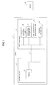
- FIG. 1 is a block diagram illustrating a configuration of a Multi-Function Peripheral (MFP) according to an embodiment of the present invention.
- MFP Multi-Function Peripheral
- a MFP 1 of the present embodiment includes an operational unit 2 having a display unit 3, and a main body 5, which has a screen generation unit 6, a setting data storage unit 7, a user authentication determination unit 8, and a function storage unit 9.
- the operational unit 2 is connected to the main body 5 via a bus 4.
- FIG. 2 is a schematic view illustrating an example of the operational unit 2.
- the operational unit 2 in addition to the display unit 3, which displays screens for operating and setting the MFP 1, and for example, includes a liquid crystal panel having a touch panel on the surface, the operational unit 2 further includes an initial setting button 21, a reset button 22, a preheat button 23, a key pad 24, a clear/stop button 25, and a start button 26.
- the screen generation unit 6 has icon data and graphic data, and is able to generate graphic window images on the display 3 acting as an operation screen for usual operations, or a setting screen for customizing the operation screen. Additionally, the screen generation unit 6 is able to control storage of setting data.
- the setting data storage unit 7, for example, is a part of a general hard disk drive (HDD) of the main body 5 of the MFP 1; further, for example, the hard disk drive is a device separate from the operational unit 2, and retains setting information of the operation screens of respective users.
- the setting data storage unit 7, or a part of the setting data storage unit 7 may be provided in a server 10 on a network.
- the user authentication determination unit 8 stores user information, and determines whether customization results of the operation screen are within the range allowed for the user who performs the setting.
- the function storage unit 9 retains a list of functions available in the MFP 1.
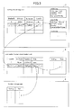
- FIG. 3 is a diagram illustrating examples of the setting data storage unit 7, the user authentication determination unit 8, and the function storage unit 9, respectively.
- the setting data storage unit 7 holds a table including items of "Display ID”, “Definition”, “Language”, and “User ID” with these items being related to each other, and system files of respective users, which are associated with the "Definition” item.
- the user authentication determination unit 8 holds a table including items of "User ID”, “UserName”, “PassWord”, “Role”, and others, and a table including items of "Setting” and “Role” related to each other. For example, when determining whether a setting value is in a range allowed for a user, the user authentication determination unit 8 determines whether the value of the item “Role” corresponding to the given value of "Setting" is within the range of the item "Role” included in the user information.
- the function storage unit 9 holds a table including items of "Function” and "Role” related to each other. For example, when determining whether a function is available to a user, the function storage unit 9 determines whether the value of the item “Role” corresponding to the given "function" is within the range of the item “Role” included in the user information.
- FIG. 4 is a sequence diagram illustrating operations from user authentication to displaying operation screens for each user.
- step S101 a user operates the display unit 3 to perform user authentication. Consequently, the log-in user (current user) is determined.
- step S102 the display unit 3 requests the screen generation unit 6 to acquire an operation screen corresponding to the log-in user.
- step S103 the screen generation unit 6 requests the setting data storage unit 7 to acquire setting information of the log-in user.
- step S104 the setting data storage unit 7 transmits the setting information to the screen generation unit 6.
- step S105 the screen generation unit 6 generates an operation screen based on the obtained setting information.
- step S106 the screen generation unit 6 sends the generated screen data to the display unit 3.
- step S107 the display unit 3 displays the operation screen to the user based on the screen data from the screen generation unit 6.
- FIG. 5A and FIG. 5B are schematic views illustrating examples of operation screens of different users.
- FIG. 5A Shown in FIG. 5A is a screen (a graphic window) for a user A to log in, and shown in FIG. 5B is a screen for a user B to log in.
- FIG. 6 is a sequence diagram illustrating operations of customizing an operation screen.
- editing a scanning screen is taken as an example.
- step S111 after the user authentication is completed, the user requests the display unit 3 to edit the scanning screen.
- FIG. 7 is a schematic view illustrating an example of an initial setting screen.
- a system initial setting button, a scan initial setting button, a printing initial setting button, and a UI screen setting button are displayed in the initial setting screen.
- the above buttons are realized by software (soft button).
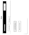
- FIG. 8 is a schematic view illustrating an example of a screen for UI screen setting.
- a screen edition tab In the screen for UI screen setting as shown in FIG. 8, there are displayed a screen edition tab, and a screen take-in tab, for example, which are also soft buttons; when the screen edition tab is clicked, a scan screen edition button and a printing screen edition button, which are soft buttons, are displayed.
- step S112 the display unit 3 requests the screen generation unit 6 to acquire a setting screen for customization by the log-in user.
- step S113 the screen generation unit 6 requests the setting data storage unit 7 to acquire setting information of the log-in user.
- step S114 the setting data storage unit 7 transmits the setting information to the screen generation unit 6.
- step S115 the screen generation unit 6 generates a setting screen based on the obtained setting information.
- step S116 the screen generation unit 6 sends the generated screen data to the display unit 3.
- step S117 the display unit 3 displays the setting screen to the user based on the screen data from the screen generation unit 6.
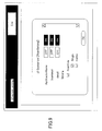
- FIG. 9 is a schematic view illustrating an example of the setting screen for setting a UI screen.
- buttons are provided for switching on or switching off the display of an item "Application Name", an item “thumbnail”, an item “detail”, and for selection of an item of "Scan Side".
- UI Customize (Scan Setting) by scrolling a scroll bar on the right side of the window, other items can be displayed and the user can perform settings appropriately for the other items. After the setting is finished, an "OK" button is clicked to finish the procedure.
- step S118 the user makes settings on the setting screen, and when the user desires to change the settings, for example, the user clicks an "OK" button as shown in FIG. 9.
- step S119 the display unit 3 informs the screen generation unit 6 that the user desires to make changes.
- step S120 the screen generation unit 6 queries the user authentication determination unit 8 whether the change of the setting is allowed.
- step S121 the user authentication determination unit 8 sends a reply to the screen generation unit 6.
- the user authentication determination unit 8 allows all of the changes if all of the changes are valid, or the user authentication determination unit 8 does not allow all or part of the changes if all or the part of the changes are not valid.
- step S122 the screen generation unit 6 requests the setting data storage unit 7 to store the changed screen settings.
- step S123 the setting data storage unit 7 sends the screen generation unit 6 a notice indicating storage of the changed screen settings.
- step S124 the screen generation unit 6 sends the changed screen setting data to the display unit 3.
- step S125 the display unit 3 displays the changed screen setting to the user.
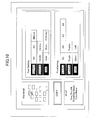
- FIG. 10 is a schematic view illustrating an example of the operation screen.
- FIG. 10 shown in FIG. 10 is an operation screen after the procedure of changing a setting is finished, and the input setting values are reflected in the operation screen.
- FIG. 11 is a schematic view illustrating an example of displaying a setting screen on the operation screen.
- a setting screen is displayed to be superposed on an operation screen, on which operation screen settings are being undertaken. Due to this, the user can constantly view the operation screen, and the user can confirm the operation screen each time a setting is made.
- the setting screen and the operation screen can be displayed on the display unit 3 side by side.
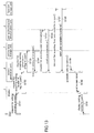
- FIG. 12 is a sequence diagram illustrating operations of reflecting changes to the setting screen to the operation screen in real-time.
- the operation screen is updated in real-time once any change is made on the setting screen. This improves operability.
- step S131 assume the setting screen and the operation screen are both displayed on the display unit 3. For example, the user is setting not to display the scan two-side button.
- step S132 the display unit 3 informs the screen generation unit 6 of the change to the scan two-side setting.
- step S133 the screen generation unit 6 queries the user authentication determination unit 8 whether the change of the setting is allowed.
- step S134 the user authentication determination unit 8 sends a reply to the screen generation unit 6.
- step S135 the screen generation unit 6 sends the changed screen setting data to the setting screen of the display unit 3.
- step S136 the display unit 3 displays the changed screen setting, which is obtained from the setting screen of the display unit 3, to the user.
- step S137 in parallel to step 135 and step 136, the screen generation unit 6 generates an operation screen including the changed settings.
- step S138 the screen generation unit 6 informs the operation screen of the display unit 3.
- step S139 the display unit 3 displays the operation screen including the changed setting to the user.
- step S140 for example, the user is setting not to display a thumbnail screen.
- step S141 the display unit 3 informs the screen generation unit 6 of the change to the thumbnail screen.
- step S142 the screen generation unit 6 queries the user authentication determination unit 8 whether the change of the setting is allowed.
- step S143 the user authentication determination unit 8 sends a reply to the screen generation unit 6.
- step S144 the screen generation unit 6 sends the changed setting of the thumbnail screen to the setting screen of the display unit 3.
- step S145 the display unit 3 displays the changed screen setting, which is obtained from the setting screen of the display unit 3, to the user.
- step S146 in parallel to step 144 and step 145, the screen generation unit 6 generates an operation screen including the changed settings.
- step S147 the screen generation unit 6 informs the operation screen of the display unit 3.
- step S148 the display unit 3 displays the operation screen including the changed setting to the user.
- FIG. 13 is a sequence diagram illustrating additional function identification operations before displaying an operation screen.
- step S151 after the user authentication is completed, the user requests the display unit 3 to edit the scanning screen.
- step S152 the display unit 3 requests the screen generation unit 6 to acquire a setting screen for customization by the log-in user.
- step S153 the screen generation unit 6 requests the setting data storage unit 7 to acquire setting information of the log-in user.
- step S154 the setting data storage unit 7 transmits the setting information to the screen generation unit 6.
- step S155 the screen generation unit 6 requests the user authentication determination unit 8 to acquire user information of the log-in user.
- step S156 the user authentication determination unit 8 sends the user information of the log-in user to the screen generation unit 6.
- step S157 the screen generation unit 6 requests the function storage unit 9 to acquire a summary of the functions available to the user.
- step S158 the function storage unit 9 sends the summary of the functions available to the user to the screen generation unit 6.
- step S159 the screen generation unit 6 generates a setting screen based on the obtained setting information and the summary of the functions available to the user.
- step S160 the screen generation unit 6 sends the generated screen data to the display unit 3.
- step S161 the display unit 3 displays the setting screen to the user based on the screen data from the screen generation unit 6.
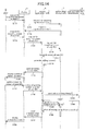
- FIG. 14 is a sequence diagram illustrating operations of re-using an operation screen of another user.
- step S171 after the user authentication is completed, the user requests the display unit 3 to acquire a list of registered screens.
- step S172 the display unit 3 requests the setting data storage unit 7 to acquire the list of registered screens.
- step S173 the setting data storage unit 7 transmits the list of registered screens to the display unit 3. Under this condition, the list of the registered user screens is displayed with each user screen of a reduced size.
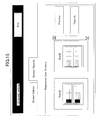
- FIG. 15 is a schematic view illustrating an example of a screen for screen take-in.
- the registered user screens of the user A and the user B are displayed on the UI screen setting screen with reduced sizes.
- step S174 the user requests the display unit 3 to acquire a screen of another user B.
- the user selects the small user screen of the user B in FIG. 15, and clicks a preview button.
- step S175 the display unit 3 requests the screen generation unit 6 to acquire the screen of user B.
- step S176 the screen generation unit 6 requests the setting data storage unit 7 to acquire the screen of user B.
- step S177 the setting data storage unit 7 transmits the screen of user B to the screen generation unit 6.
- step S178 the screen generation unit 6 generates a setting screen based on the obtained setting information.
- step S179 the screen generation unit 6 sends the generated screen data to the display unit 3.
- step S180 the display unit 3 displays the operation screen to the user.
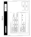
- FIG. 16 is a schematic view illustrating an example of the setting take-in previewing screen.
- the selected operation screen of the user B is displayed as a sample.
- step S181 the user instructs the display unit 3 to update the screen of the user to the screen of user B.
- step S182 the display unit 3 requests the screen generation unit 6 to update the screen of the user to the screen of user B.
- step S183 the screen generation unit 6 queries the user authentication determination unit 8 whether the change of the setting is allowed.
- step S184 the user authentication determination unit 8 sends a reply to the screen generation unit 6.
- step S185 the screen generation unit 6 requests the setting data storage unit 7 to store the changed screen settings.
- step S186 the setting data storage unit 7 sends the screen generation unit 6 a notice indicating storage of the changed screen settings.
- step S187 the screen generation unit 6 sends the changed screen setting data to the display unit 3.
- step S188 the display unit 3 displays the changed screen setting to the user.
Landscapes
- Engineering & Computer Science (AREA)
- Human Computer Interaction (AREA)
- Multimedia (AREA)
- Signal Processing (AREA)
- Facsimiles In General (AREA)
- User Interface Of Digital Computer (AREA)
- Accessory Devices And Overall Control Thereof (AREA)
Applications Claiming Priority (1)
| Application Number | Priority Date | Filing Date | Title |
|---|---|---|---|
| JP2006179981A JP2008011220A (ja) | 2006-06-29 | 2006-06-29 | 画像形成装置 |
Publications (2)
| Publication Number | Publication Date |
|---|---|
| EP1874027A1 true EP1874027A1 (de) | 2008-01-02 |
| EP1874027B1 EP1874027B1 (de) | 2013-10-09 |
Family
ID=38474407
Family Applications (1)
| Application Number | Title | Priority Date | Filing Date |
|---|---|---|---|
| EP07110830.2A Active EP1874027B1 (de) | 2006-06-29 | 2007-06-22 | Bilderzeugungsvorrichtung |
Country Status (4)
| Country | Link |
|---|---|
| US (1) | US20080016450A1 (de) |
| EP (1) | EP1874027B1 (de) |
| JP (1) | JP2008011220A (de) |
| CN (2) | CN101098384A (de) |
Cited By (4)
| Publication number | Priority date | Publication date | Assignee | Title |
|---|---|---|---|---|
| CN101938585A (zh) * | 2009-06-25 | 2011-01-05 | 株式会社理光 | 图像形成设备和信息处理方法 |
| EP2336873A3 (de) * | 2009-12-17 | 2013-02-27 | Samsung Electronics Co., Ltd. | Bilderzeugungsvorrichtung und Verfahren zur Bereitstellung lokaler Benutzerschnittstellen damit |
| EP3253041A1 (de) * | 2016-05-31 | 2017-12-06 | Brother Kogyo Kabushiki Kaisha | Informationsverarbeitungsendgerät |
| EP3314386A4 (de) * | 2015-06-23 | 2018-05-30 | Ricoh Company, Ltd. | Vorrichtung, informationsverarbeitungssystem, informationsverarbeitungsverfahren und computerprogrammprodukt |
Families Citing this family (24)
| Publication number | Priority date | Publication date | Assignee | Title |
|---|---|---|---|---|
| US7408658B2 (en) * | 2001-12-04 | 2008-08-05 | Hewlett-Packard Development Company, L.P. | Generation and usage of workflows for processing data on a printing device |
| JP4344921B2 (ja) * | 2003-08-11 | 2009-10-14 | セイコーエプソン株式会社 | Ui制御装置、ui制御方法、ui制御プログラム、印刷制御装置、印刷制御方法および印刷制御プログラム |
| JP2008219501A (ja) * | 2007-03-05 | 2008-09-18 | Ricoh Co Ltd | 画像処理装置、画像処理方法及び画像処理プログラム |
| JP5157682B2 (ja) * | 2008-03-17 | 2013-03-06 | 株式会社リコー | 情報処理装置、画像形成装置、操作画面変更方法、操作画面変更プログラムおよび記憶媒体 |
| JP5187007B2 (ja) * | 2008-06-05 | 2013-04-24 | 株式会社リコー | 画像形成装置、表示制御方法、及び表示制御プログラム |
| US9001374B2 (en) * | 2008-06-13 | 2015-04-07 | Kyocera Mita Corporation | Image forming apparatus and display control device |
| JP5295875B2 (ja) | 2008-11-06 | 2013-09-18 | シャープ株式会社 | カメラモジュールおよびそれを備えた電子機器、並びにカメラモジュールのレンズ位置決め方法 |
| JP5317802B2 (ja) * | 2009-03-31 | 2013-10-16 | 京セラドキュメントソリューションズ株式会社 | 情報処理装置、画像形成システム、及び画面データ管理プログラム |
| JP5593655B2 (ja) | 2009-08-31 | 2014-09-24 | ソニー株式会社 | 情報処理装置、情報処理方法およびプログラム |
| JP5428668B2 (ja) * | 2009-09-07 | 2014-02-26 | 株式会社リコー | ライセンス管理サーバ、ライセンス管理方法およびプログラム |
| JP5413154B2 (ja) * | 2009-11-27 | 2014-02-12 | 株式会社リコー | 表示装置、画像形成装置、カスタマイズ方法、プログラム |
| US20110205582A1 (en) * | 2010-02-19 | 2011-08-25 | Kabushiki Kaisha Toshiba | Guide display apparatus and guide display method |
| KR20120019021A (ko) * | 2010-08-24 | 2012-03-06 | 삼성전자주식회사 | 사용자 인증을 수행하는 화상형성장치 및 화상형성장치의 사용자 인증 수행 방법 |
| JP5316503B2 (ja) * | 2010-09-17 | 2013-10-16 | コニカミノルタ株式会社 | 画像形成装置、表示方法、および表示プログラム |
| CN103455370A (zh) * | 2012-05-31 | 2013-12-18 | 福建星网视易信息系统有限公司 | 一种公用设备gui界面上支持多人操作互不干扰的方法 |
| JP5634464B2 (ja) * | 2012-08-31 | 2014-12-03 | 株式会社東芝 | 管理装置および管理プログラム |
| JP2015051543A (ja) * | 2013-09-05 | 2015-03-19 | 株式会社東芝 | 印刷指示装置および印刷指示プログラム |
| US9883057B2 (en) * | 2013-12-12 | 2018-01-30 | Fuji Xerox Co., Ltd. | Processing apparatus and program product for creating, in response to user instruction, process receiving portions to be displayed differently and to perform a different process |
| JP6552341B2 (ja) * | 2015-08-28 | 2019-07-31 | キヤノン株式会社 | 画像処理装置、その制御方法、およびプログラム |
| JP6572844B2 (ja) * | 2016-07-28 | 2019-09-11 | 京セラドキュメントソリューションズ株式会社 | 用語管理システム、画像形成装置及び用語管理方法 |
| JP2018043433A (ja) | 2016-09-15 | 2018-03-22 | コニカミノルタ株式会社 | 画像形成装置 |
| KR101862766B1 (ko) * | 2017-09-20 | 2018-05-31 | 에이치피프린팅코리아 주식회사 | 사용자 인증을 수행하는 화상형성장치 및 화상형성장치의 사용자 인증 수행 방법 |
| JP6897465B2 (ja) * | 2017-09-29 | 2021-06-30 | ブラザー工業株式会社 | 表示制御装置、表示制御方法及び表示制御プログラム |
| JP7047941B2 (ja) * | 2021-01-06 | 2022-04-05 | ブラザー工業株式会社 | 画像処理装置、表示制御方法及び表示制御プログラム |
Citations (6)
| Publication number | Priority date | Publication date | Assignee | Title |
|---|---|---|---|---|
| JP2003150971A (ja) * | 2001-11-09 | 2003-05-23 | Konica Corp | 情報処理方法、情報処理システム、情報処理装置、及びプログラムを記録した情報記録媒体 |
| JP2004072131A (ja) * | 2002-06-11 | 2004-03-04 | Ricoh Co Ltd | ネットワークファクシミリ装置 |
| EP1553525A2 (de) * | 2004-01-09 | 2005-07-13 | Matsushita Electric Industrial Co., Ltd. | Multifunktionsmaschine und persönliches Authentifizierungsverfahren dafür |
| EP1574930A2 (de) * | 2004-02-25 | 2005-09-14 | Matsushita Electric Industrial Co., Ltd. | Multifunktionsvorrichtung |
| EP1599029A2 (de) * | 2004-05-19 | 2005-11-23 | Ricoh Company, Ltd. | Bilderzeugungsgerät und Verfahren zur Funktioneinstellung dafür |
| US20060101343A1 (en) | 2004-11-05 | 2006-05-11 | Masahiro Machida | Image forming apparatus, display screen customization method in image forming apparatus and display screen customization program |
Family Cites Families (28)
| Publication number | Priority date | Publication date | Assignee | Title |
|---|---|---|---|---|
| JP3762051B2 (ja) * | 1997-06-20 | 2006-03-29 | キヤノン株式会社 | 画像読取り装置及びその制御方法 |
| NL1008643C2 (nl) * | 1998-03-19 | 1999-09-23 | Oce Tech Bv | Digitale reproductie-inrichting met opslag van niet geautoriseerde en niet afdrukbare bestanden. |
| US7009728B1 (en) * | 1999-02-03 | 2006-03-07 | Minolta Co., Ltd. | Image printer system with print and save functions |
| JP2001306204A (ja) * | 2000-04-26 | 2001-11-02 | Fuji Xerox Co Ltd | ユーザー設定共用システム及び画像処理装置 |
| JP2002007011A (ja) * | 2000-06-22 | 2002-01-11 | Ricoh Co Ltd | ユーザインタフェースユニットおよび操作設定方法および機器制御システムおよび記録媒体 |
| JP2002152446A (ja) * | 2000-11-09 | 2002-05-24 | Ricoh Co Ltd | 複合機システムとそのメニュー表示方法及び記録媒体 |
| US7126710B2 (en) * | 2001-12-21 | 2006-10-24 | Xerox Corporation | Printing system employing printer-independent print quality characteristics |
| KR100595440B1 (ko) * | 2002-01-21 | 2006-07-03 | 삼성전자주식회사 | 화면차단기능을 갖는 디스플레이시스템 및 그 제어방법 |
| US20030158909A1 (en) * | 2002-02-20 | 2003-08-21 | Simpson Shell S. | Composite image generation |
| US20030160992A1 (en) * | 2002-02-28 | 2003-08-28 | Weaver Jeffrey Scott | Enabling printing features for authorized users |
| JP2004086279A (ja) * | 2002-08-23 | 2004-03-18 | Canon Inc | 画像形成装置 |
| US7149007B2 (en) * | 2002-09-26 | 2006-12-12 | Kabushiki Kaisha Toshiba | Image forming apparatus and image forming method |
| JP4402362B2 (ja) * | 2003-04-04 | 2010-01-20 | キヤノン株式会社 | 画像読取装置、その制御方法、プログラムおよび記憶媒体 |
| JP3863500B2 (ja) * | 2003-04-23 | 2006-12-27 | 京セラミタ株式会社 | 画像処理システム及び画像形成装置 |
| JP2005045370A (ja) * | 2003-07-23 | 2005-02-17 | Kyocera Mita Corp | 画像形成装置 |
| JP3808856B2 (ja) * | 2003-09-30 | 2006-08-16 | 京セラミタ株式会社 | 画像処理装置 |
| JP4566679B2 (ja) * | 2003-11-13 | 2010-10-20 | キヤノン株式会社 | 画像形成装置および制御方法およびプログラム |
| JP4408041B2 (ja) * | 2003-12-12 | 2010-02-03 | 株式会社リコー | 画像処理装置およびその制御方法 |
| JP4348201B2 (ja) * | 2004-01-21 | 2009-10-21 | パナソニック株式会社 | 複合機及び複合機における個人認証方法 |
| JP4348197B2 (ja) * | 2004-01-09 | 2009-10-21 | パナソニック株式会社 | 複合機及び複合機における個人認証方法 |
| JP4348196B2 (ja) * | 2004-01-09 | 2009-10-21 | パナソニック株式会社 | 複合機及び複合機における個人認証方法 |
| JP2005300605A (ja) * | 2004-04-06 | 2005-10-27 | Canon Inc | 画像処理装置、情報処理システム及びその制御方法 |
| JP2005335215A (ja) * | 2004-05-27 | 2005-12-08 | Ricoh Co Ltd | 画像形成装置およびその認証制御方法 |
| JP2005345860A (ja) * | 2004-06-04 | 2005-12-15 | Konica Minolta Business Technologies Inc | 画像形成装置 |
| JP4366341B2 (ja) * | 2004-07-26 | 2009-11-18 | キヤノン株式会社 | データ処理方法、データ処理システム及びコンピュータプログラム、並びに記憶媒体 |
| JP4277779B2 (ja) * | 2004-09-30 | 2009-06-10 | コニカミノルタビジネステクノロジーズ株式会社 | 画像処理システム及び同処理方法 |
| JP4455397B2 (ja) * | 2005-04-26 | 2010-04-21 | キヤノン株式会社 | 情報処理装置及びその制御方法 |
| JP4667210B2 (ja) * | 2005-11-04 | 2011-04-06 | キヤノン株式会社 | 情報処理装置、印刷装置及びそれらの制御方法、印刷システム |
-
2006
- 2006-06-29 JP JP2006179981A patent/JP2008011220A/ja active Pending
-
2007
- 2007-06-20 US US11/820,990 patent/US20080016450A1/en not_active Abandoned
- 2007-06-22 EP EP07110830.2A patent/EP1874027B1/de active Active
- 2007-06-28 CN CNA2007101279483A patent/CN101098384A/zh active Pending
- 2007-06-28 CN CN200910253411A patent/CN101729728A/zh active Pending
Patent Citations (6)
| Publication number | Priority date | Publication date | Assignee | Title |
|---|---|---|---|---|
| JP2003150971A (ja) * | 2001-11-09 | 2003-05-23 | Konica Corp | 情報処理方法、情報処理システム、情報処理装置、及びプログラムを記録した情報記録媒体 |
| JP2004072131A (ja) * | 2002-06-11 | 2004-03-04 | Ricoh Co Ltd | ネットワークファクシミリ装置 |
| EP1553525A2 (de) * | 2004-01-09 | 2005-07-13 | Matsushita Electric Industrial Co., Ltd. | Multifunktionsmaschine und persönliches Authentifizierungsverfahren dafür |
| EP1574930A2 (de) * | 2004-02-25 | 2005-09-14 | Matsushita Electric Industrial Co., Ltd. | Multifunktionsvorrichtung |
| EP1599029A2 (de) * | 2004-05-19 | 2005-11-23 | Ricoh Company, Ltd. | Bilderzeugungsgerät und Verfahren zur Funktioneinstellung dafür |
| US20060101343A1 (en) | 2004-11-05 | 2006-05-11 | Masahiro Machida | Image forming apparatus, display screen customization method in image forming apparatus and display screen customization program |
Cited By (9)
| Publication number | Priority date | Publication date | Assignee | Title |
|---|---|---|---|---|
| CN101938585A (zh) * | 2009-06-25 | 2011-01-05 | 株式会社理光 | 图像形成设备和信息处理方法 |
| CN101938585B (zh) * | 2009-06-25 | 2012-11-28 | 株式会社理光 | 图像形成设备和信息处理方法 |
| EP2336873A3 (de) * | 2009-12-17 | 2013-02-27 | Samsung Electronics Co., Ltd. | Bilderzeugungsvorrichtung und Verfahren zur Bereitstellung lokaler Benutzerschnittstellen damit |
| US8464146B2 (en) | 2009-12-17 | 2013-06-11 | Samsung Electronics Co., Ltd. | Image forming system including an image form apparatus, and method to provide local user interface using the same |
| EP3314386A4 (de) * | 2015-06-23 | 2018-05-30 | Ricoh Company, Ltd. | Vorrichtung, informationsverarbeitungssystem, informationsverarbeitungsverfahren und computerprogrammprodukt |
| US10180849B2 (en) | 2015-06-23 | 2019-01-15 | Ricoh Company, Ltd. | Apparatus, information processing system, information processing method, and computer program product |
| EP3253041A1 (de) * | 2016-05-31 | 2017-12-06 | Brother Kogyo Kabushiki Kaisha | Informationsverarbeitungsendgerät |
| US10225419B2 (en) | 2016-05-31 | 2019-03-05 | Brother Kogyo Kabushiki Kaisha | Information processing terminal generating custom operation data concerning operation identified by selected operation ID |
| US10574843B2 (en) | 2016-05-31 | 2020-02-25 | Brother Kogyo Kabushiki Kaisha | Information processing terminal generating custom operation data concerning operation identified by selected operation ID |
Also Published As
| Publication number | Publication date |
|---|---|
| CN101729728A (zh) | 2010-06-09 |
| JP2008011220A (ja) | 2008-01-17 |
| EP1874027B1 (de) | 2013-10-09 |
| CN101098384A (zh) | 2008-01-02 |
| US20080016450A1 (en) | 2008-01-17 |
Similar Documents
| Publication | Publication Date | Title |
|---|---|---|
| EP1874027B1 (de) | Bilderzeugungsvorrichtung | |
| US10298790B2 (en) | Image-forming apparatus, system, information processing method and storage medium for causing an operation screen to be displayed based on display language information | |
| JP5906667B2 (ja) | 端末装置、サーバ、画面制御方法、画面遷移方法及びコンピュータプログラム | |
| JP6066572B2 (ja) | 画像処理装置、画像処理装置の制御方法、及び制御プログラム | |
| JP2020088440A (ja) | ジョブ処理装置、ジョブ理装置の制御方法、及びプログラム | |
| CN106164843A (zh) | 显示输入装置及具备该显示输入装置的图像形成装置 | |
| JP6774019B2 (ja) | 情報処理装置およびプログラム | |
| EP1978442A2 (de) | Vorrichtung und Verfahren zur Programmerzeugung, Programm zur Umsetzung des Programmerzeugungsverfahrens und Speichermedium | |
| JP6012237B2 (ja) | 情報処理装置、制御方法、及びプログラム | |
| CN104270546B (zh) | 图像处理方法和图像形成装置 | |
| US20080030762A1 (en) | Data output control method, data output control server and data output system | |
| JP2010135965A (ja) | 画像処理装置、画像処理方法およびプログラム | |
| JP2012040765A (ja) | 画像処理装置、情報処理装置、編集プログラム、及び編集システム | |
| JP6552259B2 (ja) | 画像通信装置とその制御方法、及びプログラム | |
| US20100238517A1 (en) | Image processing device and image processing method | |
| JP2008258696A (ja) | ユーザインタフェース画面カスタマイズ装置、画面表示制御装置及びプログラム | |
| JP2021097258A (ja) | 画像処理装置、画像処理装置の制御方法、及びプログラム | |
| JP6919370B2 (ja) | 画像形成装置およびプログラム | |
| JP2020201903A (ja) | プログラム、情報処理装置、および情報処理方法 | |
| JP7006088B2 (ja) | 画像処理装置、ワークフロー実行方法、およびコンピュータプログラム | |
| US11451678B2 (en) | Image forming apparatus, image forming method, and recording medium define a folding lines to process user information in accordance with a position and a size of area in a template | |
| JP2014016847A (ja) | 情報処理装置,システム,およびプログラム | |
| JP6198903B2 (ja) | 情報処理装置、制御方法、及びプログラム | |
| JP2016148886A (ja) | 処理装置、表示方法、およびコンピュータプログラム | |
| JP6532007B2 (ja) | 画像形成装置、情報管理システムおよび情報管理方法 |
Legal Events
| Date | Code | Title | Description |
|---|---|---|---|
| PUAI | Public reference made under article 153(3) epc to a published international application that has entered the european phase |
Free format text: ORIGINAL CODE: 0009012 |
|
| 17P | Request for examination filed |
Effective date: 20070622 |
|
| AK | Designated contracting states |
Kind code of ref document: A1 Designated state(s): AT BE BG CH CY CZ DE DK EE ES FI FR GB GR HU IE IS IT LI LT LU LV MC MT NL PL PT RO SE SI SK TR |
|
| AX | Request for extension of the european patent |
Extension state: AL BA HR MK YU |
|
| AKX | Designation fees paid |
Designated state(s): DE ES FR GB IT NL |
|
| 17Q | First examination report despatched |
Effective date: 20091012 |
|
| GRAP | Despatch of communication of intention to grant a patent |
Free format text: ORIGINAL CODE: EPIDOSNIGR1 |
|
| GRAJ | Information related to disapproval of communication of intention to grant by the applicant or resumption of examination proceedings by the epo deleted |
Free format text: ORIGINAL CODE: EPIDOSDIGR1 |
|
| GRAS | Grant fee paid |
Free format text: ORIGINAL CODE: EPIDOSNIGR3 |
|
| GRAP | Despatch of communication of intention to grant a patent |
Free format text: ORIGINAL CODE: EPIDOSNIGR1 |
|
| INTG | Intention to grant announced |
Effective date: 20130808 |
|
| GRAA | (expected) grant |
Free format text: ORIGINAL CODE: 0009210 |
|
| AK | Designated contracting states |
Kind code of ref document: B1 Designated state(s): DE ES FR GB IT NL |
|
| REG | Reference to a national code |
Ref country code: GB Ref legal event code: FG4D |
|
| REG | Reference to a national code |
Ref country code: DE Ref legal event code: R096 Ref document number: 602007033209 Country of ref document: DE Effective date: 20131205 |
|
| REG | Reference to a national code |
Ref country code: NL Ref legal event code: VDEP Effective date: 20131009 |
|
| PG25 | Lapsed in a contracting state [announced via postgrant information from national office to epo] |
Ref country code: NL Free format text: LAPSE BECAUSE OF FAILURE TO SUBMIT A TRANSLATION OF THE DESCRIPTION OR TO PAY THE FEE WITHIN THE PRESCRIBED TIME-LIMIT Effective date: 20131009 |
|
| PG25 | Lapsed in a contracting state [announced via postgrant information from national office to epo] |
Ref country code: ES Free format text: LAPSE BECAUSE OF FAILURE TO SUBMIT A TRANSLATION OF THE DESCRIPTION OR TO PAY THE FEE WITHIN THE PRESCRIBED TIME-LIMIT Effective date: 20131009 |
|
| REG | Reference to a national code |
Ref country code: DE Ref legal event code: R097 Ref document number: 602007033209 Country of ref document: DE |
|
| PLBE | No opposition filed within time limit |
Free format text: ORIGINAL CODE: 0009261 |
|
| STAA | Information on the status of an ep patent application or granted ep patent |
Free format text: STATUS: NO OPPOSITION FILED WITHIN TIME LIMIT |
|
| PG25 | Lapsed in a contracting state [announced via postgrant information from national office to epo] |
Ref country code: IT Free format text: LAPSE BECAUSE OF FAILURE TO SUBMIT A TRANSLATION OF THE DESCRIPTION OR TO PAY THE FEE WITHIN THE PRESCRIBED TIME-LIMIT Effective date: 20131009 |
|
| 26N | No opposition filed |
Effective date: 20140710 |
|
| REG | Reference to a national code |
Ref country code: DE Ref legal event code: R097 Ref document number: 602007033209 Country of ref document: DE Effective date: 20140710 |
|
| REG | Reference to a national code |
Ref country code: FR Ref legal event code: PLFP Year of fee payment: 10 |
|
| REG | Reference to a national code |
Ref country code: FR Ref legal event code: PLFP Year of fee payment: 11 |
|
| REG | Reference to a national code |
Ref country code: FR Ref legal event code: PLFP Year of fee payment: 12 |
|
| P01 | Opt-out of the competence of the unified patent court (upc) registered |
Effective date: 20230522 |
|
| PGFP | Annual fee paid to national office [announced via postgrant information from national office to epo] |
Ref country code: DE Payment date: 20250618 Year of fee payment: 19 |
|
| PGFP | Annual fee paid to national office [announced via postgrant information from national office to epo] |
Ref country code: GB Payment date: 20250618 Year of fee payment: 19 |
|
| PGFP | Annual fee paid to national office [announced via postgrant information from national office to epo] |
Ref country code: FR Payment date: 20250620 Year of fee payment: 19 |