EP1874209B1 - Gerät zur erzeugung einer kugelförmigen läsion - Google Patents
Gerät zur erzeugung einer kugelförmigen läsion Download PDFInfo
- Publication number
- EP1874209B1 EP1874209B1 EP06720433A EP06720433A EP1874209B1 EP 1874209 B1 EP1874209 B1 EP 1874209B1 EP 06720433 A EP06720433 A EP 06720433A EP 06720433 A EP06720433 A EP 06720433A EP 1874209 B1 EP1874209 B1 EP 1874209B1
- Authority
- EP
- European Patent Office
- Prior art keywords
- electrode
- tines
- arrays
- electrode array
- central portion
- Prior art date
- Legal status (The legal status is an assumption and is not a legal conclusion. Google has not performed a legal analysis and makes no representation as to the accuracy of the status listed.)
- Expired - Lifetime
Links
Images


Classifications
-
- A—HUMAN NECESSITIES
- A61—MEDICAL OR VETERINARY SCIENCE; HYGIENE
- A61B—DIAGNOSIS; SURGERY; IDENTIFICATION
- A61B18/00—Surgical instruments, devices or methods for transferring non-mechanical forms of energy to or from the body
- A61B18/04—Surgical instruments, devices or methods for transferring non-mechanical forms of energy to or from the body by heating
- A61B18/12—Surgical instruments, devices or methods for transferring non-mechanical forms of energy to or from the body by heating by passing a current through the tissue to be heated, e.g. high-frequency current
- A61B18/14—Probes or electrodes therefor
- A61B18/1477—Needle-like probes
-
- A—HUMAN NECESSITIES
- A61—MEDICAL OR VETERINARY SCIENCE; HYGIENE
- A61B—DIAGNOSIS; SURGERY; IDENTIFICATION
- A61B18/00—Surgical instruments, devices or methods for transferring non-mechanical forms of energy to or from the body
- A61B18/04—Surgical instruments, devices or methods for transferring non-mechanical forms of energy to or from the body by heating
- A61B18/12—Surgical instruments, devices or methods for transferring non-mechanical forms of energy to or from the body by heating by passing a current through the tissue to be heated, e.g. high-frequency current
- A61B18/14—Probes or electrodes therefor
- A61B18/1492—Probes or electrodes therefor having a flexible, catheter-like structure, e.g. for heart ablation
-
- A—HUMAN NECESSITIES
- A61—MEDICAL OR VETERINARY SCIENCE; HYGIENE
- A61B—DIAGNOSIS; SURGERY; IDENTIFICATION
- A61B18/00—Surgical instruments, devices or methods for transferring non-mechanical forms of energy to or from the body
- A61B2018/00053—Mechanical features of the instrument of device
- A61B2018/00214—Expandable means emitting energy, e.g. by elements carried thereon
-
- A—HUMAN NECESSITIES
- A61—MEDICAL OR VETERINARY SCIENCE; HYGIENE
- A61B—DIAGNOSIS; SURGERY; IDENTIFICATION
- A61B18/00—Surgical instruments, devices or methods for transferring non-mechanical forms of energy to or from the body
- A61B2018/00636—Sensing and controlling the application of energy
- A61B2018/00898—Alarms or notifications created in response to an abnormal condition
-
- A—HUMAN NECESSITIES
- A61—MEDICAL OR VETERINARY SCIENCE; HYGIENE
- A61B—DIAGNOSIS; SURGERY; IDENTIFICATION
- A61B18/00—Surgical instruments, devices or methods for transferring non-mechanical forms of energy to or from the body
- A61B18/04—Surgical instruments, devices or methods for transferring non-mechanical forms of energy to or from the body by heating
- A61B18/12—Surgical instruments, devices or methods for transferring non-mechanical forms of energy to or from the body by heating by passing a current through the tissue to be heated, e.g. high-frequency current
- A61B18/1206—Generators therefor
- A61B2018/1246—Generators therefor characterised by the output polarity
- A61B2018/126—Generators therefor characterised by the output polarity bipolar
-
- A—HUMAN NECESSITIES
- A61—MEDICAL OR VETERINARY SCIENCE; HYGIENE
- A61B—DIAGNOSIS; SURGERY; IDENTIFICATION
- A61B18/00—Surgical instruments, devices or methods for transferring non-mechanical forms of energy to or from the body
- A61B18/04—Surgical instruments, devices or methods for transferring non-mechanical forms of energy to or from the body by heating
- A61B18/12—Surgical instruments, devices or methods for transferring non-mechanical forms of energy to or from the body by heating by passing a current through the tissue to be heated, e.g. high-frequency current
- A61B18/14—Probes or electrodes therefor
- A61B2018/1405—Electrodes having a specific shape
- A61B2018/1425—Needle
- A61B2018/143—Needle multiple needles
-
- A—HUMAN NECESSITIES
- A61—MEDICAL OR VETERINARY SCIENCE; HYGIENE
- A61B—DIAGNOSIS; SURGERY; IDENTIFICATION
- A61B18/00—Surgical instruments, devices or methods for transferring non-mechanical forms of energy to or from the body
- A61B18/04—Surgical instruments, devices or methods for transferring non-mechanical forms of energy to or from the body by heating
- A61B18/12—Surgical instruments, devices or methods for transferring non-mechanical forms of energy to or from the body by heating by passing a current through the tissue to be heated, e.g. high-frequency current
- A61B18/14—Probes or electrodes therefor
- A61B2018/1405—Electrodes having a specific shape
- A61B2018/1425—Needle
- A61B2018/1432—Needle curved
Definitions
- Fibroids, tumors and other tissue masses are often treated by ablation.
- local ablation of the diseased tissue is carried out by inserting a therapeutic device into the tissue and carrying out therapeutic activity designed to destroy the diseased cells.
- electrical energy usually alternative current of radio frequency - RF
- tissue may be ablated cryogenically, by applying heat or chemically by injecting fluids with appropriate properties to the target tissue.
- the size and shape of the region of tissue ablated depends, in part, on the configuration of the electrodes used for the procedure and on the strength of the charge applied.
- the electrical energy dissipates very rapidly with distance from the electrodes, it has been difficult to maintain desired levels of energy density within large volumes of tissue. Therefore, the ablation of larger target tissue masses has often necessitated repeated application of the ablation electrodes at multiple locations within each target tissue mass. This repetition increases the complexity, duration and cost of these procedures.
- the shapes and sizes of lesions formed by existing RF ablation systems often do not reflect the shapes of the target tissue masses.
- tumors are often generally spherical and some of them are quite large.
- the shapes of tissue masses ablated by conventional monopolar ablation systems are generally spherical, but the tissue masses affected are small, while conventional bipolar ablation methods produce bigger thermal mass, but ablate substantially cylindrical shapes. In both these cases, repeated applications and the ablation of substantial amounts of non-targeted tissue may be necessary to achieve a desired degree of ablation throughout an entire target tissue mass.
- the present invention is directed to an electrode assembly for a bi-polar ablation system comprising a first electrode array including a plurality of first tines, each of the first tines, when in a deployed configuration, extending substantially radially away from a center of the first array and including a substantially straight central portion and a second electrode array including a plurality of second tines, each of the second tines, when in the deployed configuration, extending radially away from a center of the second array and including a substantially straight central portion substantially parallel to the central portion of a corresponding one of the first tines.
- An exemplary method for ablating tissue is also disclosed, using the assembly according to the invention, comprising deploying a first electrode array at a first desired position relative to a target tissue mass to be ablated, the first array comprising a plurality of first tines, each of the deployed first tines including a substantially straight central portion and deploying a second electrode array at a second desired position relative to the target tissue mass, the second array comprising a plurality of second tines, each of the deployed second tines including a substantially straight central portion, the central portions of the first and second tines being oriented and positioned so that a distance between corresponding pairs of the first and second tines is substantially constant along the lengths thereof, the second desired position being separated from the first desired position by a distance between one quarter and one half of a deployed diameter of the first and second arrays in combination with applying one of RF and electrical energy to the first and second arrays to ablate a first portion of the target tissue mass, repositioning at least one of the first and second arrays to a third desired position relative to
- Embodiments of the present invention relate to methods and systems for ablating targeted tissues within a patient's body.
- the embodiments are related to the ablation of target tissues using electric energy of radio frequency.
- one or more electrodes are placed in contact with or adjacent to a target tissue mass and electric or RF energy is applied to the electrodes to necrose the tissue of the target tissue mass.
- electrodes are placed within the target tissue mass, for example, by puncturing an outer surface of the target tissue and inserting the electrodes therein.
- RF ablation systems typically fall into one of two broad categories: monopolar and bipolar.
- Monopolar systems include only one active electrode which is inserted into the body in, or adjacent to, the target tissue mass.
- a dispersive electrode, or other similar device is placed on the skin of the patient to provide a return path for the electric current A "loop" is thus formed, which includes the active electrode, the target tissue and the dispersive electrode.
- Bipolar electrode systems include two active electrodes of alternating polarity both of which are inserted in close proximity to one another adjacent to the target tissue mass. Bipolar systems tend to be more efficient since both active electrodes produce heat near the target tissue mass allowing delivered energy to be better focused on the target tissue mass. Shaping and positioning the electrodes of a bipolar system also allows the shape of the region tissue ablated to be maximized and more closely controlled.
- the size of the lesions which can be produced by monopolar systems is limited as only one implanted electrode is used.
- multi-tine electrodes such as the LEVEEN NeedleTM manufactured by Boston Scientific Oncology Division
- larger target tissue masses may require multiple applications before they are fully treated.
- Half the energy transmitted in monopolar systems is dissipated at the dispersive electrode without producing heat.
- the path along which current will flow to the dispersive electrode cannot be completely predicted.
- energy may be applied to non-targeted tissue possibly including tissue to which it is desired not to apply energy.
- the generally cylindrical lesion shapes obtained using conventional bipolar systems are not well suited to treat many tumors, which tend to be substantially spherical. Additional procedures are carried out at times to modify the shape of the resulting lesion. For example, water cooling or saline injections may be made in and around the target tissue mass, to inhibit or enhance the transfer of heat to portions of tissue selected to generate a lesion of a desired shape. These procedures increase the complexity, time and cost of the RF/electrical ablation treatment, and may not always provide acceptable results.
- Embodiments of the present invention allow the formation of large spherical lesions without performing additional procedures or employing additional devices which complicate the procedure.
- Embodiments of the present invention may thus be used to treat large, substantially spherical tumors in one setting, while minimizing injury to surrounding non-targeted tissues, and without requiring insertion of the electrodes in different regions of the target tissue mass.
- Q i 2 ⁇ Z ⁇ ⁇ t
- a lesion will continue to grow so long as an amount of energy deposited exceeds an outlfow of heat (Q>F) as the component A of the second equation would grow to balance the energy deposited. If the tissue were not subject to any external cooling processes, the lesion would continue to grow for as long as a temperature differential was maintained (i.e., for as long as electrical energy were supplied to the tissue). However, if external cooling is applied to the system, the rate of deposition of electrical energy into the tissue would need to continually increase to indefinitely continue increasing the size of the lesion. Over time, the power required would increase significantly as the increase in the surface area of the ablated region would increase and, consequently, the heat flow would increase as well. When the power of an electrical energy source remains constant, a thermal equilibrium condition is reached as the lesion reaches an equilibrium size where the energy dispersed over the surface area of the lesion is no longer sufficient to ablate the contiguous tissue. Thus, lesion grows no further.
- larger surface area electrodes inject more current or power into the tissue, while maintaining a lower electrode surface current density and, consequently, a lower electrode surface temperature.
- many electrode designs have maximized the surface area of the electrodes positioned in a given volume of target tissue.
- the dispersive electrode of a monopolar system is much larger and further away from the electrode placed in contact with the target tissue, current from each element of the active electrode spreads in all directions, forming an equipotential surface that, depending on the properties of the surrounding tissue, may approximate a sphere.
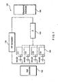
- a monopolar RF ablation system may be modeled by approximating it with an equivalent electrical circuit as shown in Figure 1 .
- the RF generator 110 has a hot, or active electrode 102 which is placed in contact with or adjacent to a target tissue mass.
- C1, C2, C3 ... Cn represent electrical contact points 104 formed at small areas of an interface between tissue and the surface of the electrode 102.
- the elements of the active electrode 102 all have substantially the same electrical resistance Z with respect to the dispersive electrode 108, due to the long path between these electrodes, which translates into high resistance.
- the difference in the paths between the dispersive electrode 108 and the various contact points 104 is insubstantial (i.e., within the dimensions of the active electrode).
- the difference in resistance along these paths is not significant and may be ignored.
- the current density over the various contact points 104 is substantially constant.
- the surrounding tissue heats up and its impedance drops, increasing the current density. Since all of the contact points 104 along the electrode 102 are in substantially the same electrical situation, this process goes on uniformly across the surface of the electrode 102. At some point, however, vapor begins to form at the interface between the electrode 102 and the tissue creating an insulating layer between the electrode 102 and the tissue. In the schematic diagram of Fig. 1 , this is shown by opening one or more of the contact points 104.
- current density decreases in proportion to the square of the distance from the probe.
- the RF power heats only a small portion of tissue which is typically located within a few millimeters of the surface of the electrode 102.
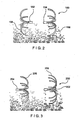
- FIG. 2 shows one type of RF ablation system 150, in which tines 156, 158 of the two arrays 152, 154 are shaped like opposing open umbrellas to encompass a generally spherical target tissue volume.
- Figure 3 shows a second common bipolar system 200, in which the arrays 202, 204 are oriented substantially in the same direction. In the latter configuration, the insertion and deployment of the tines 206, 208 may be easier, especially if they are inserted in the same direction from a single incision.
- each of the arrays of electrodes may be placed further apart. As shown in Fig. 7 , under these conditions, each of the arrays of electrodes acts substantially as a separate monopolar electrode forming lesions 207 therearound. Depending on the spacing of the arrays 202, 204, it may be very difficult to combine such lesions into a larger, unitary lesion beyond a small central connection area 209.
- Figs. 8 - 10 show a multi-stage ablation method.
- the electrode arrays 202, 204 are placed closer to one another and energy is applied to form an initial lesion of limited size which also represents a volume 211 of higher impedance.
- the electrode arrays 202, 204 are spread further apart (e.g., a distal electrode is pushed forward and a proximal electrode is pulled back) with the initial lesion/high impedance volume 211 centered therebetween.
- the active electrode arrays are preferably positioned close to one another (e.g., separated by a distance less than a radial extent of the arrays).
- the initial lesion will extend further in the radial dimension than axially.
- Subsequent lesions will increase the axial extent of the lesion more quickly than the radial extent as the electrode arrays 202, 204 are separated further from one another making the lesion more spherical.
- an electrical system substantially equivalent to such a bipolar system 250 comprises an RF generator 256 operatively connected to electrode arrays 252, 254 via conventional conductors and connectors.
- the electrode arrays 252, 254 may be, for example, umbrella shaped arrays of tines as described above.
- the contacts C1, C2, C3, Cn represent interface contacts between the surfaces of the electrode arrays 252, 254 and the tissue 262.
- the different resistances Z1, Z2, Z3, Zn, connected in parallel, represent the different path lengths between the elements of the electrodes 252, 254. Since the resistances are all unequal, the system produces different current densities i1, i2, i3...i n through the portions of tissue 262.
- the temperature distribution along the elements of the electrode arrays 252, 254 is quite uneven with higher temperatures at the surfaces of those elements of the electrode arrays 252, 254 close to one another creating a higher impedance drop in the these regions which, in turn, results in an even higher current density in these regions.
- a snowball effect thus can take place with high temperatures leading to lower impedances which lead to even higher temperatures.
- the snowball effect typically ends quickly when the temperature of the closest corresponding elements of the opposing arrays 252, 254 becomes sufficiently high to cause the formation of vapor.
- Vapor around the electrodes effectively opens a contact in the equivalent circuit, for example at C1 in the diagram, and shuts off the heating from that element This in turn increases the overall impedance between the electrode arrays 252, 254 and reduces the current and power which may be deposited into the tissue by the electrode arrays 252, 254.
- this mechanism places a limit to the size of the lesion which can be obtained using conventional electrode arrays 252, 254 of the type described above.
- the shape and volume of the area affected by the current distribution between the electrodes 252, 254 when in close proximity to one another depends on the distance between the elements of the electrodes 252, 254.
- each one of the pair acts like a point source, distributing current in all directions with a current density distribution that is substantially inversely proportional to the square of the distance to the element.
- the electrode arrays 252, 254 are close to one another, current is conducted more directly between paired elements approximating a straight line along an axis between the elements.
- the current density distribution between the elements in this case is substantially inversely proportional to the first power distance to the elements.
- the axis is a line substantially perpendicular to planes in which tips of the electrodes 252, 254 reside.
- Figure 5 shows an example of an energy volume 280 between electrode elements 282, 284.
- the current density and energy applied to target tissue are significantly different than the current density and energy applied between pairs of elements that are further from one another as represented by the energy volume 280' of Fig. 5B .
- the energy applied to tissue along a current path between elements that are close to one another is inversely proportional to the square of the distance as opposed to being proportional to the fourth power of the distance for elements further from one another.
- the lesions formed are larger axially than radially and the lesion formation time is shorter because of the snowball effect, limiting the size of the lesions which can be created.
- Figure 6 shows an exemplary embodiment of a bipolar RF ablation system 300 according to the present invention comprising first and second electrode arrays 302, 304, respectively.
- the geometry of the tines 306, 308 of the first and second arrays 302, 304, respectively, is such that it is possible to bring the two arrays in close proximity after they have been deployed within or adjacent to the target tissue mass.
- the two arrays 302, 304 may be moved toward one another to a distance of less than half the diameter of the array, while ensuring that none of the elements of the first array 302 contact any of the elements of second array 304 avoiding the problem of short circuit.
- the tines of each array are shaped to promote a more uniform distribution of current within the target tissue.
- the tines 306 and 308 comprise, respectively, linear portions 310, 312 which face each other when the arrays of tines 302, 304 are deployed.
- the linear portions 310, 312 result in a substantially uniform distance between corresponding ones of tines 306, 308, at least along the lengths of the linear portions 310, 312 which may, for example, comprise the majority of the lengths of the tines 306, 308.
- the substantially uniform distance between the tines 306, 308 helps to maintain a more uniform current density along the surfaces of the electrode arrays 302, 304, and generates a more uniform application of energy to the surrounding tissue.
- the close and substantially uniform distance between the tines 306,308 allows the generation of a substantially uniform current density distribution between the arrays 302, 304 as shown in Fig. 5A .
- energy distribution along the tines 306, 308 and along the axis is substantially uniform preventing the snowball effect and resulting in a larger, more homogeneous lesion. This may be especially valuable when using a multistep ablation process.
- employing the system 300 careful selection of the initial and subsequent distances between the electrodes 302, 304 will allow the creation of large, substantially cylindrical lesions.
- the linear portions 310, 312 are preferably arranged in first and second planes substantially perpendicular to the central axis. However, for other reasons associated, for example, with deployment and storage during insertion, the tines may deploy so that the linear portions 310, 312 are located along portions of first and second cones with an angle of the cones being between 60 and 90 degrees.
- the exemplary bipolar system 300 is preferably inserted to the target tissue mass in a folded, insertion configuration, as is common for RF ablation electrodes.
- the arrays of tines 302, 304 are deployed using conventional mechanisms as would be understood by those skilled in the art to an extended, operative configuration which, in the exemplary embodiment, comprises a substantially circular, umbrella-like shape.
- a translation mechanism is preferably provided to move the arrays of tines 302, 304, for example, along a longitudinal axis of the system 300 to deploy the arrays 302, 304.
- core portions 314 of the arrays 302, 304 are preferably connected to this mechanism to extend the tines 306, 308 from and retract the tines 306, 308 into a cannula or sheath as would be understood by those skilled in the art.
- the mechanism may also provide for translation of the arrays of tines 302, 304 along the longitudinal axis relative to one another, to vary the distance therebetween.
- a method of use of the system 300 according to an exemplary embodiment of the present invention is described with reference to Figs. 6 and 11-13 .
- RF energy is applied to the target tissue mass via the electrode arrays 302, 304.
- this first energy application may be carried out with the linear portions 310, 312 of the tines 306, 308 separated from one another by a distance between approximately one quarter and one half of the diameter of the arrays 302, 304 to generate a lesion/high impedance area 305 in the target tissue having a large transverse size as compared to its length along the axis A. That is, the lesion initially generated will have a greater extent in a plane extending substantially perpendicular to an axis A of the system 300 than it has along the axis A.
- the electrode arrays 302, 304 are repositioned further from one another near a transition region between the previously formed lesion/high impedance area 305 and the surrounding non-ablated tissue to further enlarge the lesion 305 along the axis A.
- the high impedance area 305 is now located between the electrode arrays 302, 304.
- Current then flows between the electrode arrays 302, 304 around the initial lesion/high impedance region 305 through initially unaffected tissue creating a substantially spherical combined lesion 307.
Landscapes
- Health & Medical Sciences (AREA)
- Life Sciences & Earth Sciences (AREA)
- Surgery (AREA)
- Engineering & Computer Science (AREA)
- Plasma & Fusion (AREA)
- General Health & Medical Sciences (AREA)
- Otolaryngology (AREA)
- Physics & Mathematics (AREA)
- Veterinary Medicine (AREA)
- Biomedical Technology (AREA)
- Heart & Thoracic Surgery (AREA)
- Medical Informatics (AREA)
- Molecular Biology (AREA)
- Animal Behavior & Ethology (AREA)
- Nuclear Medicine, Radiotherapy & Molecular Imaging (AREA)
- Public Health (AREA)
- Cardiology (AREA)
- Surgical Instruments (AREA)
Claims (9)
- Elektrodenanordnung für ein bipolares Ablationssystem (300), aufweisend:eine erste Elektrodenanordnung (302) enthaltend mehrere erste Zinken (306), wobei sich jede der ersten Zinken (306), wenn sie in einer entfalteten Konfiguration sind, sich im Wesentlichen radial von einer Mitte der ersten Elektrodenanordnung (302) weg erstreckt; undeine zweite Elektrodenanordnung (304), enthaltend mehrere zweite Zinken (308), wobei jede der zweiten Zinken (308), wenn sie in der entfalteten Konfiguration sind, sich im Wesentlichen radial von einer Mitte der zweiten Elektrodenanordnung (304) weg erstreckt; undwobei die erste Elektrodenanordnung (302) und die zweite Elektrodenanordnung (304) an einem Entfaltungsmechanismus entlang der Mitten der ersten und der zweiten Elektrodenanordnung (302, 304) befestigt sind;dadurch gekennzeichnet, dass, wenn sie in einer entfalteten Konfiguration sind, jede der ersten Zinken (306) einen im Wesentlichen geraden mittleren Teil (310) und jede der zweiten Zinken (308) einen im Wesentlichen geraden mittleren Teil (312), der im Wesentlichen parallel zu dem mittleren Teil (310) einer entsprechenden der ersten Zinken (306) ist, enthalten, wobei ein im Wesentlichen gleichförmiger Abstand zwischen den linearen Teilen (310, 312) so vorhanden ist, dass eine gleichförmige Stromdichte zwischen den Zinken (306, 308) aufrechterhalten wird.
- Elektrodenanordnung nach Anspruch 1, bei der die erste (302) und die zweite (304) Elektrodenanordnung für eine Bewegung relativ zueinander entlang einer Achse (A) befestigt sind.
- Elektrodenanordnung nach Anspruch 2, bei der, wenn die erste (302) und die zweite (304) Elektrodenanordnung entlang der Achse (A) zueinander hin bewegt werden, Elemente der ersten Elektrodenanordnung (302) Elemente der zweiten Elektrodenanordnung (304) nicht berühren, wenn ein Abstand zwischen der ersten (302) und der zweiten (304) Elektrodenanordnung zumindest angenähert ein Viertel eines Durchmessers der ersten (302) und der zweiten (304) Elektrodenanordnung ist, wenn die erste (302) und die zweite (304) Elektrodenanordnung in der entfalteten Konfiguration sind.
- Elektrodenanordnung nach Anspruch 1, bei der jede der ersten Zinken (306) einen proximalen Teil, der zwischen einen Kern (314) der ersten Elektrodenanordnung (302) und den mittleren Teil (310) gekoppelt ist, und einen distalen Teil, der sich von einem distalen Ende des mittleren Teils (310) erstreckt, aufweist, wobei der Kern (314) der ersten Elektrodenanordnung sich im Wesentlichen parallel zu einer ersten Achse der ersten Elektrodenanordnung (302) erstreckt und wobei die proximalen Teile, wenn sie in der entfalteten Konfiguration sind, sich von den proximalen Enden hiervon im Wesentlichen parallel zu dem Kern (314) weg zu distalen Enden, die sich radial von der ersten Achse weg erstrecken, hin krümmen.
- Elektrodenanordnung nach Anspruch 1, bei der jede der zweiten Zinken (308) einen proximalen Teil, der zwischen einen Kern (314) der zweiten Elektrodenanordnung (304) und den mittleren Teil (312) gekoppelt ist, und einen distalen Teil, der sich von einem distalen Ende des mittleren Teils (312) weg erstreckt, aufweist, wobei sich der Kern (314) der zweiten Elektrodenanordnung im Wesentlichen parallel zu einer zweiten Achse der zweiten Elektrodenanordnung (304) erstreckt und wobei die proximalen Teile, wenn sie in der entfalteten Konfiguration sind, sich von den proximalen Enden hiervon im Wesentlichen parallel zu dem Kern (314) weg zu distalen Enden, die sich radial von der zweiten Achse weg erstrecken, hin krümmen.
- Elektrodenanordnung nach Anspruch 1, bei der die erste (302) und die zweite (304) Elektrodenanordnung zwischen der entfalteten Konfiguration und einer Einführungskonfiguration, in der die ersten (306) und zweiten (308) Zinken im Wesentlichen parallel zu der ersten bzw. zweiten Achse gefaltet sind, bewegbar sind, um den äußeren Durchmesser der ersten (302) und der zweiten (304) Anordnung zu minimieren.
- Elektrodenanordnung nach Anspruch 1, bei der die mittleren Teile (310) der ersten Zinken (306) ausgebildet sind, um mit den mittleren Teilen (312) der entsprechenden zweiten Zinken (308) zusammenzuwirken, um eine im Wesentlichen gleichförmige Stromdichteverteilung zwischen zumindest solchen Teilen der ersten (302) und der zweiten (304) Elektrodenanordnung, die an die mittleren Teile (310, 312) der ersten (306) und der zweiten (308) Zinken angrenzen, zu erzeugen.
- Elektrodenanordnung nach Anspruch 1, bei der der mittlere Teil (310, 312) jeder der ersten (306) und der zweiten (308) Zinken einen größeren Teil der Länge hiervon aufweist.
- Bipolares Ablationssystem (300), welches aufweist:eine Kanüle;eine Elektrodenanordnung nach den Ansprüchen 1 bis 8,wobei die erste (302) und die zweite (304) Elektrodenanordnung innerhalb der Kanüle für eine Bewegung zwischen einer Einführungskonfiguration, in der die ersten Zinken (306) der ersten Elektrodenanordnung (302) und die zweiten Zinken (308) der zweiten Elektrodenanordnung (304) innerhalb der Kanüle aufgenommen sind, und der entfalteten Konfiguration, in der die ersten (306) und die zweiten (308) Zinken sich im Wesentlichen von der Kanüle radial auswärts erstrecken, befestigt sind; undeine Quelle (256) für HF- oder elektrische Energie, die mit der ersten (302) und der zweiten (304) Elektrodenanordnung so koppelbar ist, dass Energie von entgegengesetzter Polarität zu der ersten (302) bzw. der zweiten (304) Elektrodenanordnung geliefert wird.
Applications Claiming Priority (2)
| Application Number | Priority Date | Filing Date | Title |
|---|---|---|---|
| US11/114,829 US7806893B2 (en) | 2005-04-26 | 2005-04-26 | Apparatus and method for making a spherical lesion |
| PCT/US2006/004266 WO2006115565A1 (en) | 2005-04-26 | 2006-02-06 | Apparatus and method for making a spherical lesion |
Publications (2)
| Publication Number | Publication Date |
|---|---|
| EP1874209A1 EP1874209A1 (de) | 2008-01-09 |
| EP1874209B1 true EP1874209B1 (de) | 2010-12-22 |
Family
ID=36168928
Family Applications (1)
| Application Number | Title | Priority Date | Filing Date |
|---|---|---|---|
| EP06720433A Expired - Lifetime EP1874209B1 (de) | 2005-04-26 | 2006-02-06 | Gerät zur erzeugung einer kugelförmigen läsion |
Country Status (5)
| Country | Link |
|---|---|
| US (1) | US7806893B2 (de) |
| EP (1) | EP1874209B1 (de) |
| JP (1) | JP5122442B2 (de) |
| DE (1) | DE602006019078D1 (de) |
| WO (1) | WO2006115565A1 (de) |
Families Citing this family (7)
| Publication number | Priority date | Publication date | Assignee | Title |
|---|---|---|---|---|
| US20060207607A1 (en) | 2005-02-08 | 2006-09-21 | Mark Hirotsuka | System and method for percutaneous palate remodeling |
| US7794458B2 (en) * | 2005-07-22 | 2010-09-14 | Boston Scientific Scimed, Inc. | Bipolar radio frequency ablation device with retractable insulator |
| US9314299B2 (en) | 2012-03-21 | 2016-04-19 | Biosense Webster (Israel) Ltd. | Flower catheter for mapping and ablating veinous and other tubular locations |
| US10799283B2 (en) | 2014-07-28 | 2020-10-13 | Boston Scientific Scimed, Inc. | Multiple lead electrode probe for controlled tissue ablation |
| US11523858B2 (en) | 2017-08-11 | 2022-12-13 | Bradley D. Vilims | System and method for RF ablation with generated images of ablated tissue lesions |
| CN112075958B (zh) * | 2019-06-13 | 2024-05-07 | 上海交通大学医学院附属第九人民医院 | 一种穿刺取样装置 |
| CN114767256A (zh) * | 2022-01-27 | 2022-07-22 | 苏州心岭迈德医疗科技有限公司 | 一种电极间距变化的消融导管及设备 |
Family Cites Families (12)
| Publication number | Priority date | Publication date | Assignee | Title |
|---|---|---|---|---|
| US5885278A (en) * | 1994-10-07 | 1999-03-23 | E.P. Technologies, Inc. | Structures for deploying movable electrode elements |
| US5868740A (en) * | 1995-03-24 | 1999-02-09 | Board Of Regents-Univ Of Nebraska | Method for volumetric tissue ablation |
| US6575967B1 (en) * | 1995-03-24 | 2003-06-10 | The Board Of Regents Of The University Of Nebraska | Method and systems for volumetric tissue ablation |
| US5792140A (en) * | 1997-05-15 | 1998-08-11 | Irvine Biomedical, Inc. | Catheter having cooled multiple-needle electrode |
| US7520877B2 (en) * | 2000-06-07 | 2009-04-21 | Wisconsin Alumni Research Foundation | Radiofrequency ablation system using multiple prong probes |
| US8486065B2 (en) * | 2000-06-07 | 2013-07-16 | Wisconsin Alumni Research Foundation | Radio-frequency ablation system and method using multiple electrodes |
| US7387628B1 (en) * | 2000-09-15 | 2008-06-17 | Boston Scientific Scimed, Inc. | Methods and systems for focused bipolar tissue ablation |
| US20050065509A1 (en) * | 2003-09-22 | 2005-03-24 | Scimed Life Systems, Inc. | Flat electrode arrays for generating flat lesions |
| DE10345023A1 (de) | 2003-09-24 | 2005-04-21 | Biotronik Gmbh & Co Kg | Ablationskatheter |
| US7416549B2 (en) * | 2003-10-10 | 2008-08-26 | Boston Scientific Scimed, Inc. | Multi-zone bipolar ablation probe assembly |
| WO2005048862A2 (en) * | 2003-11-18 | 2005-06-02 | Scimed Life Systems, Inc. | System and method for tissue ablation |
| US7524318B2 (en) * | 2004-10-28 | 2009-04-28 | Boston Scientific Scimed, Inc. | Ablation probe with flared electrodes |
-
2005
- 2005-04-26 US US11/114,829 patent/US7806893B2/en not_active Expired - Fee Related
-
2006
- 2006-02-06 DE DE602006019078T patent/DE602006019078D1/de not_active Expired - Lifetime
- 2006-02-06 WO PCT/US2006/004266 patent/WO2006115565A1/en not_active Ceased
- 2006-02-06 EP EP06720433A patent/EP1874209B1/de not_active Expired - Lifetime
- 2006-02-06 JP JP2008508830A patent/JP5122442B2/ja not_active Expired - Fee Related
Also Published As
| Publication number | Publication date |
|---|---|
| JP5122442B2 (ja) | 2013-01-16 |
| JP2008538977A (ja) | 2008-11-13 |
| US20060241738A1 (en) | 2006-10-26 |
| WO2006115565A1 (en) | 2006-11-02 |
| DE602006019078D1 (de) | 2011-02-03 |
| US7806893B2 (en) | 2010-10-05 |
| EP1874209A1 (de) | 2008-01-09 |
Similar Documents
| Publication | Publication Date | Title |
|---|---|---|
| EP1576932B1 (de) | Vorrichtung zur Ablation von Gewebemassen | |
| US6575967B1 (en) | Method and systems for volumetric tissue ablation | |
| US9339328B2 (en) | Multi-electrode energy delivery device and method of using the same | |
| US7025767B2 (en) | Tumor ablation needle with independently activated and independently traversing tines | |
| US9060782B2 (en) | Devices and methods for thermal ablation of biological tissue using geometric ablation patterns | |
| US8951250B2 (en) | Ablation probe with flared electrodes | |
| EP1853188B1 (de) | Vorrichtung zur wärmeablation biologischen gewebes über kugelförmige ablationsstrukturen | |
| US9144457B2 (en) | Ablation probe with distal inverted electrode array | |
| US20060089635A1 (en) | Methods and apparatus for focused bipolar tissue ablation using an insulated shaft | |
| US20070260237A1 (en) | Windowed thermal ablation probe | |
| US20060217702A1 (en) | Ablation probe having a plurality of arrays of electrodes | |
| JP2004267759A (ja) | 骨内神経ion含む骨を治療するための方法、椎体の神経bvnを含む椎体を治療するための方法、骨内神経を除神経する装置、健康な椎体を治療するための方法、骨内神経を除神経するシステム、および、椎体および椎体の神経bvnを治療するための方法 | |
| JP7179957B2 (ja) | 双極灌注式高周波アブレーション分岐プローブ | |
| EP1874209B1 (de) | Gerät zur erzeugung einer kugelförmigen läsion |
Legal Events
| Date | Code | Title | Description |
|---|---|---|---|
| PUAI | Public reference made under article 153(3) epc to a published international application that has entered the european phase |
Free format text: ORIGINAL CODE: 0009012 |
|
| 17P | Request for examination filed |
Effective date: 20071019 |
|
| AK | Designated contracting states |
Kind code of ref document: A1 Designated state(s): DE FR GB IE |
|
| RAP1 | Party data changed (applicant data changed or rights of an application transferred) |
Owner name: BOSTON SCIENTIFIC LIMITED |
|
| 17Q | First examination report despatched |
Effective date: 20080318 |
|
| RIN1 | Information on inventor provided before grant (corrected) |
Inventor name: OSTROVSKY, ISAAC Inventor name: FAIRNENY, TY |
|
| RBV | Designated contracting states (corrected) |
Designated state(s): DE FR GB IE |
|
| DAX | Request for extension of the european patent (deleted) | ||
| GRAP | Despatch of communication of intention to grant a patent |
Free format text: ORIGINAL CODE: EPIDOSNIGR1 |
|
| RTI1 | Title (correction) |
Free format text: APPARATUS FOR MAKING A SPHERICAL LESION |
|
| GRAS | Grant fee paid |
Free format text: ORIGINAL CODE: EPIDOSNIGR3 |
|
| GRAA | (expected) grant |
Free format text: ORIGINAL CODE: 0009210 |
|
| AK | Designated contracting states |
Kind code of ref document: B1 Designated state(s): DE FR GB IE |
|
| REG | Reference to a national code |
Ref country code: GB Ref legal event code: FG4D |
|
| REG | Reference to a national code |
Ref country code: IE Ref legal event code: FG4D |
|
| REF | Corresponds to: |
Ref document number: 602006019078 Country of ref document: DE Date of ref document: 20110203 Kind code of ref document: P |
|
| REG | Reference to a national code |
Ref country code: DE Ref legal event code: R096 Ref document number: 602006019078 Country of ref document: DE Effective date: 20110203 |
|
| PLBE | No opposition filed within time limit |
Free format text: ORIGINAL CODE: 0009261 |
|
| STAA | Information on the status of an ep patent application or granted ep patent |
Free format text: STATUS: NO OPPOSITION FILED WITHIN TIME LIMIT |
|
| REG | Reference to a national code |
Ref country code: FR Ref legal event code: ST Effective date: 20111102 |
|
| GBPC | Gb: european patent ceased through non-payment of renewal fee |
Effective date: 20110322 |
|
| 26N | No opposition filed |
Effective date: 20110923 |
|
| REG | Reference to a national code |
Ref country code: DE Ref legal event code: R097 Ref document number: 602006019078 Country of ref document: DE Effective date: 20110923 |
|
| PG25 | Lapsed in a contracting state [announced via postgrant information from national office to epo] |
Ref country code: FR Free format text: LAPSE BECAUSE OF NON-PAYMENT OF DUE FEES Effective date: 20110228 |
|
| PG25 | Lapsed in a contracting state [announced via postgrant information from national office to epo] |
Ref country code: GB Free format text: LAPSE BECAUSE OF NON-PAYMENT OF DUE FEES Effective date: 20110322 |
|
| REG | Reference to a national code |
Ref country code: DE Ref legal event code: R082 Ref document number: 602006019078 Country of ref document: DE Representative=s name: PFENNING MEINIG & PARTNER GBR, DE |
|
| REG | Reference to a national code |
Ref country code: DE Ref legal event code: R081 Ref document number: 602006019078 Country of ref document: DE Owner name: BOSTON SCIENTIFIC LIMITED, BM Free format text: FORMER OWNER: BOSTON SCIENTIFIC LTD., HASTINGS, CHRIST CHURCH, BB Effective date: 20150202 Ref country code: DE Ref legal event code: R082 Ref document number: 602006019078 Country of ref document: DE Representative=s name: PFENNING MEINIG & PARTNER GBR, DE Effective date: 20150202 Ref country code: DE Ref legal event code: R082 Ref document number: 602006019078 Country of ref document: DE Representative=s name: PFENNING, MEINIG & PARTNER MBB PATENTANWAELTE, DE Effective date: 20150202 |
|
| PGFP | Annual fee paid to national office [announced via postgrant information from national office to epo] |
Ref country code: DE Payment date: 20200121 Year of fee payment: 15 Ref country code: IE Payment date: 20200210 Year of fee payment: 15 |
|
| REG | Reference to a national code |
Ref country code: DE Ref legal event code: R119 Ref document number: 602006019078 Country of ref document: DE |
|
| PG25 | Lapsed in a contracting state [announced via postgrant information from national office to epo] |
Ref country code: DE Free format text: LAPSE BECAUSE OF NON-PAYMENT OF DUE FEES Effective date: 20210901 Ref country code: IE Free format text: LAPSE BECAUSE OF NON-PAYMENT OF DUE FEES Effective date: 20210206 |