EP1874514B1 - Dispositif pour produire des blocs agglomeres de beton - Google Patents
Dispositif pour produire des blocs agglomeres de beton Download PDFInfo
- Publication number
- EP1874514B1 EP1874514B1 EP06723846A EP06723846A EP1874514B1 EP 1874514 B1 EP1874514 B1 EP 1874514B1 EP 06723846 A EP06723846 A EP 06723846A EP 06723846 A EP06723846 A EP 06723846A EP 1874514 B1 EP1874514 B1 EP 1874514B1
- Authority
- EP
- European Patent Office
- Prior art keywords
- holding
- clamping
- mold insert
- mould insert
- counter
- Prior art date
- Legal status (The legal status is an assumption and is not a legal conclusion. Google has not performed a legal analysis and makes no representation as to the accuracy of the status listed.)
- Expired - Lifetime
Links
Images


Classifications
-
- B—PERFORMING OPERATIONS; TRANSPORTING
- B28—WORKING CEMENT, CLAY, OR STONE
- B28B—SHAPING CLAY OR OTHER CERAMIC COMPOSITIONS; SHAPING SLAG; SHAPING MIXTURES CONTAINING CEMENTITIOUS MATERIAL, e.g. PLASTER
- B28B7/00—Moulds; Cores; Mandrels
- B28B7/0002—Auxiliary parts or elements of the mould
- B28B7/0014—Fastening means for mould parts, e.g. for attaching mould walls on mould tables; Mould clamps
-
- B—PERFORMING OPERATIONS; TRANSPORTING
- B28—WORKING CEMENT, CLAY, OR STONE
- B28B—SHAPING CLAY OR OTHER CERAMIC COMPOSITIONS; SHAPING SLAG; SHAPING MIXTURES CONTAINING CEMENTITIOUS MATERIAL, e.g. PLASTER
- B28B1/00—Producing shaped prefabricated articles from the material
- B28B1/08—Producing shaped prefabricated articles from the material by vibrating or jolting
- B28B1/087—Producing shaped prefabricated articles from the material by vibrating or jolting by means acting on the mould ; Fixation thereof to the mould
-
- B—PERFORMING OPERATIONS; TRANSPORTING
- B28—WORKING CEMENT, CLAY, OR STONE
- B28B—SHAPING CLAY OR OTHER CERAMIC COMPOSITIONS; SHAPING SLAG; SHAPING MIXTURES CONTAINING CEMENTITIOUS MATERIAL, e.g. PLASTER
- B28B3/00—Producing shaped articles from the material by using presses; Presses specially adapted therefor
- B28B3/02—Producing shaped articles from the material by using presses; Presses specially adapted therefor wherein a ram exerts pressure on the material in a moulding space; Ram heads of special form
- B28B3/022—Producing shaped articles from the material by using presses; Presses specially adapted therefor wherein a ram exerts pressure on the material in a moulding space; Ram heads of special form combined with vibrating or jolting
Definitions
- the invention relates to an apparatus for the production of concrete blocks by compacting fresh concrete in a molding machine under the action of shaking forces.
- a mold insert is removably mounted in a holding frame, which is vertically movable along vertical guide columns of a molding machine.
- the mold insert can be placed on a pad located below the mold frame and pressed by the holding frame on the substrate and can be excited by means of a vibrator to vibrate.
- a ballast with stamp plates is lowered into the upper openings of the mold cavity and presses on the fresh concrete.
- the pad is z. B. excited by rotating unbalanced masses or blow bars to vibrations, which are also transmitted to the mold insert and the fresh concrete.
- the compacted molded bodies can be removed from the mold cavities, for which purpose the mold frame is moved upwards and the stamps of the ballast hold the moldings on the substrate.
- the mold insert which is bolted to the support frame, is forced over the support frame with high force on the support. Between the pressing force transmitting, vertically opposite surfaces of support frame and mold insert a layer of damping material is inserted.
- a device in which a mold consists of a mold frame and a mold insert which is held in the mold frame by interposition of elastically prestressed damping material exists, which are handled as a form together and are not separated by the user. About flange strips on the outside of the mold frame, the mold in clamping positions of the molding machine is firmly clamped.
- a device according to the WO 03/092973 The forces between the mold frame and mold insert during the Rüttelvorgangs by a thin elastic layer, with which a gap between the mold frame and mold insert is poured, collected.
- the DE 103 33 743 A1 describes a device for the production of concrete blocks according to the preamble of claim 1, which contains a mold frame and a mold insert held therein. Attached to the mold frame holding elements engage with interposition of fluid-filled damping elements in recesses of the mold insert. The holding elements can be arranged displaceably on the mold frame, whereby the insert can be removed from the mold frame. From the DE 951 797 C is a stone forming machine is known in which a molding box is placed on a task table and held on an engagement of guide rods and guide sleeves on the work table.
- At one of the DE 203 01 954 U1 known device for shaping mixtures is a mold insert via bracing elements with a vibrating table, to which a harmonic oscillation system is attached coupled. To replace the mold, the bracing elements are released.
- the invention has for its object to provide an advantageous device for the production of concrete blocks.
- a releasable clamping device between mold insert and vibratory pad on the one hand and a releasable holding device between a machine-side support frame and the mold insert on the other hand results in an advantageous functional separation of different compounds of the mold insert in different periods of successive manufacturing cycles.
- a releasable clamping device between mold insert and vibratory pad on the one hand and a releasable holding device between a machine-side support frame and the mold insert on the other hand results in an advantageous functional separation of different compounds of the mold insert in different periods of successive manufacturing cycles.
- Of particular advantage is the possibility of loose coupling or preferably complete decoupling of the mold insert from the holding frame in the vibrating phase. In particular, no vertical contact forces between holding frame and mold insert are transmitted.
- the mold insert between two shaking in the engaged position of the holding devices on this with the holding frame, in particular its vertical mobility relative to the vibratory pad so rigidly coupled that a precise immersion of a pressure plate Auflastvoriques in the at least one mold cavity and the precise vertical position are reliably ensured by printing plates and bottom edge of the mold cavity during demolding.
- the insert is thus manageable as a conventional mold insert during filling and demolding.
- the power coupling between the holding frame and mold insert on the holding device is preferably completely canceled or greatly reduced so that during the vibration process, the holding frame measurable acceleration maximum 20%, in particular maximum 10% of the acceleration on the holding means connected part of the mold insert.
- the holding devices and clamping devices are automatically, in particular via a pressurized fluid, preferably hydraulically actuated.
- a control device in coordination with other actuators of the molding machine controls the timely operation of the holding devices and clamping devices.
- shock vibration can be used with blow bars.
- a vibrating device with vibration exciters between the base and a counterweight advantageously has a counterweight to the mold insert on the opposite.
- the holding devices advantageously have movable, preferably automatic, sides of the holding frame connected to the forming machine operable holding elements and on the side of the mold insert only passive counter-elements for releasable engagement with the holding elements.
- the passive counter-elements may in particular be openings in the mold insert into which the holding elements can be inserted.
- the holding elements are designed in an advantageous embodiment at least at their end facing the mold insert bolt-shaped.
- the opening in the mold insert is advantageously expanded on the holding frame facing away from the end of a region for the engagement of the holding elements and open at the bottom.
- the holding devices between the release position and the engagement position are substantially immovable and contain holding elements whose power coupling between the holding frame and mold insert is variable.
- the holding elements contain fluid-filled hollow body whose force coupling is adjustable by changing the fluid pressure via leads to the hollow bodies.
- the holding elements may contain magnetic coils which generate magnetic fields for the engagement position, in particular repulsive magnetic fields, wherein preferably on the side of the mold insert permanent magnets are arranged.
- the extensive decoupling of the holding frame from the mold insert during the shaking process, in particular the elimination of the vertical contact forces between the holding frame and mold insert also significantly simplifies the attachment a vertically movable in the molding machine and fixed during the shaking holding frame.
- the holding frame is advantageously made of only two arranged on opposite sides of the mold insert and individually connected to the molding machine retaining flanges or retaining strips.
- the support frame but in other embodiments, the mold insert as a U-shape to three or closed on all four sides surrounded.
- the holding elements hold the mold insert in a horizontal plane advantageously in a defined position, so that no further centering for precise alignment of mold insert and printing plates of a Auflastvoriques are necessary.
- the holding elements support the mold insert in a position lifted from the vibrating support, in particular during the demolding of the compacted concrete moldings from the mold insert.
- Clamping elements of the clamping devices engage advantageously from below into the mold insert in counter-elements, in particular in downwardly open and preferably closed up against the incidence of fresh concrete openings in the bottom of the mold insert.
- Clamping elements and counter-clamping elements are advantageously designed to rotate relative to each other.
- Contact surfaces for clamping the clamping devices can then advantageously be formed at least approximately as helical sections about the axis of rotation of clamping element or counter-clamping element.
- the clamping elements and counter-clamping elements engage in one another via a thread.
- the clamping devices brace for the shaking the mold insert against the pad with a force which is typically sufficient to to reliably prevent a lateral displacement of the decoupled from the frame mold insert on the pad.
- centering elements can be provided between the vibrating pad and the mold insert, which engage positively with one another on the vibrating pad mold insert with structures and counter-structures and determine the position of the mold insert on the vibrating pad and secure against horizontal displacement of the mold insert relative to the pad.
- an intermediate layer usually in the form of a wooden board, which serves mainly for the one-layer production as a support for the removal and storage of the concrete moldings ,
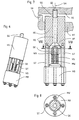
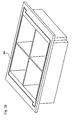
- Fig. 1 shows in an oblique view from above a vertically movable in a molding machine in the vertical z-direction holding frame in which vertically spaced from a Rüttelunterlage a mold insert is held.
- the support frame consists in the preferred example outlined of two arranged in the horizontal ⁇ -direction of the marked coordinate system on opposite sides of the mold insert FE retaining strips HLL, HLR.
- the retaining strips are permanently connected to the machine and provided for receiving various interchangeable mold inserts.
- the retaining strips are vertically movable in a conventional manner for holding frame by means of hydraulic cylinders and guided in vertical guides, which may also be formed by the hydraulic cylinder itself. For reasons of clarity, only the vertical guides are indicated by the molding machine.
- the mold insert has in a central region a stone field with a plurality of mold cavities FN, which form up and down open receptacles for fresh concrete or a similar mixture.
- the mold cavities essentially determine the shape of the concrete moldings produced on the mold insert.
- connection areas ABL and ABR which in sketched example zoom up to a narrow gap SP to the associated retaining strips.
- connection areas ABL and ABR counter holding elements are arranged to holding devices between retaining strips and mold insert and counter-clamping elements of clamping devices for vertical clamping of the mold insert against the Studttelunterlage, which hereinafter with reference to advantageous Embodiments are illustrated.
- the engaged holding means determine the horizontal position of the mold insert with respect to the retaining strips and couple the mold insert to the vertical displacement of the retaining strips along the vertical guides.
- the vibratory pad is shown in the example sketched as a rectangular vibrating table RT, which can be excited to vibrations only schematically indicated vibrators RE, the vibrations preferably have predominantly vertical components.
- vibrating devices which are known per se to the person skilled in the art, in particular vibratory devices which can be removed from the aforementioned prior art, can be used with harmonic unbalance vibration or shock vibration via blow bars.
- the amplitudes of the excited vibrations of the vibrating table are typically in a range between 0.5 mm and 5 mm.
- a stone board SB which typically consists of wood or plastic, placed on the mold insert facing top of the vibrating table is in a conventional manner.
- the stone board SB does not occupy the entire table width of the vibrating table RT in the ⁇ direction.
- lateral areas SSL, SSR of the vibrating table are provided with clamping elements SE of clamping devices.
- the clamping elements protrude in the sketched embodiment on the table surface upwards and also on the underside of the table down.
- the counter-clamping elements of the clamping devices are arranged in the connection areas ABL, ABR of the mold insert, preferably on its underside. Particularly advantageous embodiments of such clamping devices are described below in detail.
- the stone board is, in particular in one-layer production as a transport and storage pad with the compacted and demolded concrete moldings from the vibrating table in the x direction shifted, which is why along this Board edge no tensioning elements over the table surface stand out, and replaced by an empty stone board.
- a loading device is also included in the molding machine which is well known and known in the art Fig. 1 for the sake of clarity is not shown.
- the loading device engages stamping plates into the upper openings of the mold filled with fresh concrete and exerts pressure on the concrete during the vibration process.
- the printing plates also serve to reliably demould the compacted concrete moldings from the mold cavities downward by moving the mold insert relative to them upwardly after completion of the vibrating operation with substantially constant vertical relative position of stone board and printing plates and leaving the compacted concrete moldings on the stone plank.
- FIG. 2 is shown between the holding frame forming retaining strips HLL, HLR held mold insert in plan view, wherein the holding means between the holding frame and mold insert are shown partially cut.
- the retaining strips are shown simplified without the connection to the vertical guides of the molding machine.
- FIG. 3 to FIG. 5 show enlarged sections with various of the several holding devices.
- the holding devices HE1, HE2, HE3 and HE4 are each formed by a holding element on the side of the retaining strip and a counter-holding element on the side of the mold insert.
- the holding elements are transverse to each other on the gap SP opposite wall surfaces of retaining strip and mold insert, preferably substantially perpendicular to these wall surfaces linearly displaceable.
- the holding elements HB are advantageously bolt-like at least at their ends facing the mold insert with a western constant cross section.
- the counter-holding elements in the mold insert comprise in particular an opening, preferably as a bore, in the wall of the mold insert, which is slightly larger than the cross section of the bolt-shaped holding elements.
- the holding elements can be displaced between an engagement position with ends projecting into the openings GB and a release position withdrawn from the opening.
- the displacement takes place via arranged in the retaining strips actuating means, which are preferably designed as pressure-medium-actuated cylinder.
- the horizontal displacement of the holding elements allows a low overall height of the terminal areas ABL, ABR and is thus advantageously suitable for mold inserts to low heights of z. B. only a few centimeters.
- the holding elements HB are secured in the retaining strips and by the engagement in the openings GB of the mold insert there against tilting about the direction of displacement and therefore stabilize in the engaged position, the position of the mold insert in each case transversely to the respective direction of displacement.
- advantageously different holding devices are aligned with different displacement directions of the linearly displaceable holding elements.
- the holding devices HE1 and HE3 have a direction of displacement parallel to the ⁇ direction and stabilize the position of the mold insert against relative displacements of the mold insert and holding frame in the x and in the z direction, the holding means HE2 and HE4 act with positional parallel to the x direction displacement directions against relative displacements in ⁇ and z directions.
- stabilization of the position of the mold insert in the holding frame in all directions is ensured with simply designed holding devices.
- the course of the Column SP in the drawing plane of the Fig. 2 advantageously deviated from a linear course deviating.
- the gap other equivalent courses are possible.
- the mold insert is surrounded on several sides by the holding frame, in particular holding elements can also be arranged on frame sections extending in the ⁇ -direction.
- the gap is preferably only air-filled. From above incident dirt can fall down.
- dirt particles which in the release position of the holding devices are attached to holding elements HB and / or openings GB are pressed into the openings when changing to the engagement position, these openings are gradually filled, the openings GB are widened at the ends facing away from the holding strips ,
- the widenings ER are advantageously open at the bottom. As a result, dirt particles passing into the opening are displaced beyond the engagement area of the opening GB into the widening ER when the retaining element HB is moved into the engagement position and drop downwards.
- additional stop elements preferably made of elastic material for limiting the movement of the mold insert relative to the holding frame in the x-y plane may be provided.
- the gap may be provided in another embodiment with a sealing device for sealing against the ingress of dirt, but which should be easily deformable and neither vertical holding forces for lifting the mold insert of the Schwarzttelunterlage nor vertical contact forces during the Schwarzttelvorgangs has applied and no appreciable shares the shaking movement of the mold insert is to be transferred to the retaining strips.
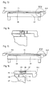
- Fig. 3 is the holding device HE1 as a section along III - III of Fig. 2 shown.
- a holding element HB is sketched here in an intermediate position between the extended position and complete engagement in the cylindrical engagement region of the opening GB.
- the opening has at its the retaining strip HLL opposite end an expansion ER on, which is open at the bottom.
- the lower boundary plane UE of the mold insert in the region of the mold cavity is lower than the lower surface of the terminal region ABL.
- the surface of the mold insert is in the example outlined in an upper boundary plane OE from the region of the mold cavities on the connection area ABL continuous, but may also be stepped or have a cover plate or a rail for a filling carriage in a conventional manner.
- the height of the mold insert between the upper and lower boundary of the mold cavities is denoted by EH.
- connection area ABL is also still a counter-clamping element GS a clamping device indicated.
- Fig. 2 Positions of several such counter-clamping elements GS are indicated in the connection areas.
- Fig. 4 shows a section through the holding device HE2 along IV - IV of Fig. 2 , From this view, the preferred circular symmetric cross section of holding element HB and opening GB can be seen as well as the advantageous extension of the expansion ER also down.
- Fig. 5 shows the holding device HE3 as a cutout V from Fig. 2 in partially cutaway view.
- the widening ER is approximately half a truncated cone in the sketched example.
- the mold insert is, as already Fig. 1 designed to be clamped by releasable clamping devices against the vibratory pad to prevent uncontrolled lifting of the mold insert from the vibrating table RT and the stone board SB during the shaking process.
- the clamping devices comprise clamping elements SE on the side of the vibrating table in lateral areas SSL, SSR and counter-clamping elements on the side of the mold insert, preferably on the underside of the connection areas ABL, ABR, which can detachably mesh with each other and can apply a high vertical clamping force between vibrating table and mold insert.
- Fig. 6 to Fig. 8 is outlined a preferred embodiment of clamping elements.
- the sketched clamping element contains in particular a about a vertical screw axis SA rotatable clamping screw SS, which is supported on the vibrating table against tensile forces upwards.
- the clamping screw engages with its screw thread SG in a mating thread GG as a counter-clamping element in the mold insert FE, preferably in a connection area ABL, ABR as to Fig. 1 to Fig. 5 already explained, and clamped when tightening the threaded connection mold insert and vibrating vertically against each other.
- the turning of the clamping screw is preferably carried out by a motor MO.
- the clamping screw S is supported with its screw head SK on the sleeve HS and guided with its shaft through the sleeve upwards.
- a drive shaft MW of the engine engages, z. B. a polygon, in the sketch to Fig. 8 a square cross-section in the screw head SK, so that rotation of the screw and rotation of the motor shaft are coupled.
- the motor shaft is only inserted in the screw head, so that in case of a defect or wear components of the clamping element can be replaced individually.
- Motor MO and sleeve HS are connected in the example outlined on more screws ST and kept at a defined distance.
- the sleeve HS can be inserted into the vibrating table from below and / or be welded into the vibrating table.
- the structure of the sleeve HS can be formed even without the sleeve as a separate component in the table body of the vibrating table itself.
- the clamping screw SS against a restoring force in the direction of placement of the mold insert on the vibrating table ie be displaced in the z-direction.
- a restoring force is in the example of FIGS. 7 to 9 applied by a compression spring VS.
- the displaceability against the restoring force allows the placement of the mold insert on the vibrating table RT or the stone board SB before the clamping screw SS is screwed with its screw thread into a counter thread GG as a counter-clamping element on the side of the mold insert.
- the clamping screw is then at its upper end under the action of the restoring force of the spring VS at the entrance of the counter thread GG, which in Fig. 7 in the bottom of a connection region ABR of a mold insert FE is indicated.
- the seat WA in the screw head for the drive shaft MW of the motor in the z-direction is sufficiently deep to allow immersion of the end of the driving motor shaft MW in the recording upon displacement of the screw down.
- the support of the clamping screw SS in the sleeve against vertical tensile forces advantageously takes place via conical bearing surfaces AF of the sleeve and the screw head, whereby any incidental dirt particles along the sloping surfaces fail down.
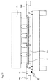
- a mold insert with retaining strips and a vibratory pad are shown at several stages of a manufacturing cycle in a molding machine, with overall side views and enlarged details shown.
- the vibrator device, the vertical guide of the retaining strips, the load-bearing device and other assemblies of the molding machine are not shown.
- Fig. 9 the mold insert FE is held with engaged holding means in the retaining strips HLL, HLR of the mold insert and vertically spaced from the Haittelunterlage with vibrating table RT and stone board SB.
- the in Fig. 10 enlarged cutout X out Fig. 9 shows that a holding element HB engages from the retaining strip HLR via the gap SP in the counter-holding element in the connection area ABR of the mold insert.
- the clamping elements SE on the side of the vibrating table are not in contact with the counter-clamping elements of the mold insert.
- the clamping screw SS is pressed by the restoring force of the spring VS in the clamping element in its upper position in the connected to the vibrating table sleeve HS.
- the holding element HB is still in engagement with the counter-holding element in the mold insert, but in this position, in the ideal case substantially free of stress, since the weight of the mold insert now rests on the stone board SB.
- the actuation of the clamping devices can advantageously be carried out in two stages, wherein in a first stage, all clamping screws are screwed with low torque in the mating thread and in a second stage tightening the screws with high torque to achieve a strong vertical tension.
- the high torque tightening in the second stage may occur before or even after release of the retainers.
- the mold insert together with the vibrating table and the stone board, performs vibrating movements relative to the holding frame fixed in the molding machine.
- the pressure plates of the loader further lower in the degree of compaction of the concrete in the mold cavities.
- the mold insert can now by moving the holding frame up in the in Fig. 21 shown position are lifted from the stone board, but with the load device AL drawn here is not lifted and the pressure plates DP hold the compacted concrete moldings BK on the stone board, so that when lifting the mold insert FE the concrete moldings BK are removed from the mold cavities.
- the clamping screws are pressed by the restoring forces of the springs back in the sleeves in their upper position.
- the vertical position of the holding frame and the mold insert must be maintained relatively accurately, so that the concrete moldings are reliably expressed from the mold cavities, but the printing plates still remain in the mold cavities.
- the vertical movement of the mold insert relative to vibrating table and / or Auflastvoriques can also be done in fixed in the molding machine holding frame and vertical movements of vibrating table or Auflastvorses.
- the operation of the holding frame and the Auflastvoriques in the molding machine, the operation of the holding devices and the clamping devices and the vibrator and the coordinated control optionally further operations within a cycle is advantageously carried out automatically or partially automatically by a control unit of the molding machine with manual triggering of individual cycle steps.
- a control unit of the molding machine with manual triggering of individual cycle steps.
- sensors can be provided for the current position of holding elements and / or clamping elements or of corresponding additional elements.
- the functions of the exemplary described holding devices which secure the mold insert in all directions in a defined position relative to the holding frame can also be divided on the vertical position of the holding frame and mold insert coupling support elements without centering on the one hand and the horizontal position of the mold insert relative to the support frame in an xy plane determining centering on the other hand, which are actuated simultaneously or successively.
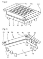
- Fig. 22 is in an oblique view from above and in Fig. 23 sketched from below a combination of support frame, mold insert and vibrating table with stone board, in which the mold insert has a much greater height between the lower and upper boundary plane of the stone field with the mold cavities.
- the handling of this mold insert is carried out substantially the same as in the preceding examples described in detail, but here are formed on the mold insert counter-holding elements in the z-direction clearly spaced from the counter-clamping elements.
- the position of the counter-holding elements and the counter-clamping elements in the x- and ⁇ -directions is substantially the same for all the different shapes, and the relative vertical Position DG of the counter-clamping elements for all different shapes in the z-direction with respect to the lower boundary plane UE of the mold inserts is the same.
- the position DH of the counter-holding elements in the z-direction with respect to the upper boundary plane OE for all mold inserts is the same.
- the mentioned relative position sizes in the z-direction are in Fig. 25 on an enlarged section from the sectional view Fig.
- mold insert FE whose arbitrary height HEV is indicated by the horizontal interruption illustrated.
- the mold inserts of different heights can then be used particularly advantageously with the same holding frame with holding elements and the same vibrating table with clamping elements, and show without further structures in each case a uniform upper side with the upper boundary plane OE
- connection area below an upper plate portion AP in which the counter-holding elements are indicated, compared to a solid block shape to the arranged on the underside of the mold insert counter-clamping elements larger recesses AA exhibit.
- the counter-clamping elements are in the example of FIGS. 22 and 23 arranged on the undersides of material webs MS.
- Fig. 26 is outlined in oblique view a combination of a mold insert with this surrounding on all four sides closed support frame HR.
- additional centering between vibrating and mold insert may be provided which are provided when placing the mold insert, which at Placing the mold insert on the vibrating table or during clamping by means of the clamping devices engage and in addition to the high-strength Fixing the mold insert on the vibrating table in the xy plane still cause a positive position securing.
- FIGS. 22 to 25 in the case of higher mold inserts in a preferred embodiment, it is assumed that the holding devices between the machine-side holding frame and the mold insert lie in the defined upper level DH of the mold insert DH and thus always without additional structure a constant upper limit over which the filling carriage is guided given is, may be given in another embodiment, a certain constant altitude between the holding devices and the lower boundary plane UE of the mold insert.
- Such a design is far more adapted to conventional molding machines, as they usually proceed with a machine-side clamping bar for receiving a flange of an interchangeable mold for placing the mold insert on the stone board or the vibrating table, the clamping bar up to a fixed stop in the machine down.
- Fig. 27 is from diagonally above and in Fig. 28 sketched obliquely from below a mold insert, wherein at the bottom of a base plate GP as connection area the stone field with the several mold star laterally surmounted and contains both the counter holding elements of the holding devices in the form of holes GB with extensions ER and the counter-clamping elements in the form of mating thread GG.
- the area of the stone field is widened laterally by a cover plate HP.
- the outer edges of the cover plate form connecting edges AKM for machine-side supports or guide plates, which are arranged on several sides adjacent to the cover plate during the filling process.
- the cover plate HP is supported by gussets KN, which are attached to side surfaces of the insert and preferably extend to the base plate GP.
- Fig. 29 is such a mold insert FEL at any height HEL in side view and in Fig. 30 an enlarged section XXX out of it sketched.
- the counter holding elements GB are arranged in a relative height position DHL which is the same for all mold inserts with respect to the lower boundary plane UE of the mold insert.
- the position of the counter holding elements is defined by a defined line of the counter holding elements, for. B. represents the center axis of a hole.
- Fig. 31 an advantageous possibility of supplementing existing molding machines is sketched to a device according to the invention.
- Conventional molding machines each have on both sides of a receiving space for a mold or a mold insert a machine flange MF with a predetermined connection pattern for a mold.
- the shape in turn has on opposite sides depending on a flange in the machine flange corresponding design.
- the machine flanges MF are each provided with a retaining strip HL, which in the sense of the present invention have machine-side holding elements HB of the holding devices between the forming frame and the mold insert.
- the retaining strips HL can be permanently connected to the machine flanges for use with several different inserts, e.g. B. bolted or welded, or clamped on the type of common form flanges only on the machine flanges and each be interchangeable with the mold insert.
- Fig. 32 is a device after Fig. 31 with inserted mold insert outlined. Connections for actuating the retaining elements HB, in particular pressure medium connections and lines are preferably provided exclusively in the retaining strips HL.
Landscapes
- Engineering & Computer Science (AREA)
- Manufacturing & Machinery (AREA)
- Chemical & Material Sciences (AREA)
- Ceramic Engineering (AREA)
- Mechanical Engineering (AREA)
- Moulds, Cores, Or Mandrels (AREA)
- Press-Shaping Or Shaping Using Conveyers (AREA)
- Manufacturing Of Tubular Articles Or Embedded Moulded Articles (AREA)
Claims (21)
- Dispositif pour produire des blocs de béton moulés par compactage de béton frais dans une machine de moulage avec un cadre de maintien côté machine (HLL, HLR, HR), une base vibrante (RT) et une grille de moulage (FE) avec au moins une niche de moulage (FN), qui peut être maintenue sur la base (RT) pendant une opération de vibration et qui peut être déplacée verticalement par rapport à la base (RT) pour le démoulage dudit au moins un corps de béton moulé compacté hors de la niche de moulage (FN), caractérisé en ce que- il est prévu des dispositifs de serrage (SE) pour le serrage de la grille de moulage (FE) contre la base (RT) et des dispositifs de maintien (HE1, HE2, HE3, HE4) pour le maintien de la grille de moulage (FE) dans le cadre de maintien (HLL, HLR, HR),- les dispositifs de maintien (HE1, HE2, HE3, HE4) et les dispositifs de serrage (SE) peuvent être actionnés automatiquement,- pendant une opération de vibration, les dispositifs de serrage (SE) serrent la grille de moulage (FE) contre la base (RT) et les dispositifs de maintien (HE1, HE2, HE3, HE4) se trouvent dans une position libre entre la grille de moulage (FE) et le cadre de maintien (HLL, HLR, HR),- pour le démoulage, les dispositifs de serrage (SE) sont desserrés et les dispositifs de maintien (HE1, HE2, HE3, HE4) se trouvent dans une position d'engagement, et- le couplage de force entre la grille de moulage (FE) et le cadre de maintien (HLL, HLR, HR) dans la position libre des dispositifs de maintien (HE1, HE2, HE3, HE4) est plus faible que dans leur position d'engagement.
- Dispositif selon la revendication 1, caractérisé en ce qu'un dispositif de commande commande l'actionnement des dispositifs de maintien (HE1, HE2, HE3, HE4) et/ou des dispositifs de serrage (SE) au cours d'un cycle de production.
- Dispositif selon la revendication 1 ou 2, caractérisé en ce que le cadre de maintien présente au moins deux barres de maintien (HLL, HLR) placées horizontalement l'une en face de l'autre et enfermant entre elles la grille de moulage.
- Dispositif selon la revendication 3, caractérisé en ce que le cadre de maintien entoure la grille de moulage (FE) sur trois côtés ou de façon fermée sur tous les côtés.
- Dispositif selon l'une quelconque des revendications 1 à 4, caractérisé en ce que les dispositifs de maintien (HE1, HE2, HE3, HE4) maintiennent la grille de moulage (FE) dans toutes les directions dans une position définie par rapport au cadre de maintien (HLL, HLR, HR).
- Dispositif selon l'une quelconque des revendications 1 à 5, caractérisé en ce que les dispositifs de maintien (HE1, HE2, HE3, HE4) comprennent des éléments de maintien mobiles, en particulier mobiles linéairement, entre le cadre de maintien (HLL, HLR, HR) et la grille de moulage (FE).
- Dispositif selon la revendication 6, caractérisé en ce que des éléments de maintien différents (HB) sont mobiles dans des directions différentes, en particulier orthogonales l'une à l'autre.
- Dispositif selon l'une quelconque des revendications 1 à 7, caractérisé en ce que des éléments de maintien (HB) s'engagent dans des ouvertures de maintien (GB) de la grille de moulage (FE).
- Dispositif selon la revendication 8, caractérisé en ce que les ouvertures présentent des élargissements (ER) situés à l'opposé du cadre de maintien (HLL, HLR, HR).
- Dispositif selon la revendication 9, caractérisé en ce que les élargissements (ER) sont ouverts vers le bas.
- Dispositif selon l'une quelconque des revendications 1 à 5, caractérisé en ce que les dispositifs de maintien (HE1, HE2, HE3, HE4) comprennent des éléments de maintien (HB) stationnaires, dont le couplage de force peut changer.
- Dispositif selon la revendication 11, caractérisé en ce que les éléments de maintien (HB) pouvant changer de couplage de force sont des corps creux remplis de fluide et la pression du fluide peut changer via des conduites d'alimentation des corps creux pour faire varier le couplage de force.
- Dispositif selon la revendication 11, caractérisé en ce que les éléments de maintien (HB) pouvant changer de couplage de force comprennent des bobines magnétiques.
- Dispositif selon l'une quelconque des revendications 1 à 13, caractérisé en ce que les dispositifs de serrage (SE) comprennent un élément de serrage rotatif (SS).
- Dispositif selon la revendication 14, caractérisé en ce que l'élément de serrage rotatif (SS) est disposé sur des côtés de la base vibrante (RT) et s'engage pour le serrage dans un élément de serrage opposé (GG) sur des côtés de la grille de moulage (FE).
- Dispositif selon la revendication 15, caractérisé en ce que l'élément de serrage opposé (GG) est réalisé sous la forme d'une ouverture dans la face inférieure de la grille de moulage (FE).
- Dispositif selon la revendication 15 ou 16, caractérisé en ce que l'élément de serrage (SS) et/ou l'élément de serrage opposé (GG) présente(nt) une face d'appui sous la forme d'une partie d'hélice autour de l'axe de rotation (SA) de l'élément de serrage.
- Dispositif selon la revendication 14, caractérisé en ce que l'élément de serrage et l'élément de serrage opposé s'engagent l'un dans l'autre au moyen d'un filet (SG, GG).
- Dispositif selon l'une quelconque des revendications 1 à 18, caractérisé en ce que des éléments de serrage (SS) sur des côtés de la base (RT) et des éléments de serrage opposés (GG) sur des côtés de la grille de moulage (FE) reposent l'un sur l'autre avant d'avoir atteint la position finale lors de la pose de la grille de moulage sur la base, et sont mobiles dans la direction de pose contre une force de rappel et ils reposent l'un sur l'autre à l'état précontraint par l'action de la force de rappel lorsque la grille de moulage est posée sur la base.
- Dispositif selon l'une quelconque des revendications 1 à 19, caractérisé en ce qu'il est prévu des dispositifs de centrage entre la base (RT) et la grille de moulage (FE).
- Dispositif selon l'une quelconque des revendications 1 à 20, caractérisé en ce que des dispositifs de serrage (SE) et/ou des dispositifs de maintien (HE1, HE2, HE3, HE4) peuvent être actionnés par un fluide sous pression, en particulier par voie hydraulique.
Priority Applications (1)
| Application Number | Priority Date | Filing Date | Title |
|---|---|---|---|
| PL06723846T PL1874514T3 (pl) | 2005-04-16 | 2006-03-30 | Urządzenie do wytwarzania kształtek betonowych |
Applications Claiming Priority (2)
| Application Number | Priority Date | Filing Date | Title |
|---|---|---|---|
| DE102005017669A DE102005017669A1 (de) | 2005-04-16 | 2005-04-16 | Vorrichtung zur Herstellung von Betonformsteinen |
| PCT/EP2006/002879 WO2006111253A2 (fr) | 2005-04-16 | 2006-03-30 | Dispositif pour produire des blocs agglomeres de beton |
Publications (2)
| Publication Number | Publication Date |
|---|---|
| EP1874514A2 EP1874514A2 (fr) | 2008-01-09 |
| EP1874514B1 true EP1874514B1 (fr) | 2012-10-03 |
Family
ID=36572358
Family Applications (1)
| Application Number | Title | Priority Date | Filing Date |
|---|---|---|---|
| EP06723846A Expired - Lifetime EP1874514B1 (fr) | 2005-04-16 | 2006-03-30 | Dispositif pour produire des blocs agglomeres de beton |
Country Status (6)
| Country | Link |
|---|---|
| EP (1) | EP1874514B1 (fr) |
| DE (1) | DE102005017669A1 (fr) |
| DK (1) | DK1874514T3 (fr) |
| ES (1) | ES2395302T3 (fr) |
| PL (1) | PL1874514T3 (fr) |
| WO (1) | WO2006111253A2 (fr) |
Families Citing this family (1)
| Publication number | Priority date | Publication date | Assignee | Title |
|---|---|---|---|---|
| CN114347214B (zh) * | 2021-12-08 | 2024-06-25 | 中建科工集团有限公司 | 混凝土测试块制作装置 |
Family Cites Families (7)
| Publication number | Priority date | Publication date | Assignee | Title |
|---|---|---|---|---|
| FR710287A (fr) * | 1930-01-27 | 1931-08-20 | Machine à mouler par secousses pour la compression de briques | |
| DE951797C (de) * | 1955-01-11 | 1956-10-31 | Schlosser & Co G M B H | Steinformmaschine mit hoehenverstellbarem Aufgabetisch |
| SU988560A1 (ru) * | 1981-06-02 | 1983-01-15 | Конструкторско-Технологическое Бюро Республиканского Промышленного Объединения "Укртяжстройиндустрия" Министерства Строительства Предприятий Тяжелой Индустрии Усср | Устройство дл креплени формы на виброплощадке |
| DE19508152A1 (de) * | 1995-03-08 | 1996-09-12 | Kobra Formen & Anlagenbau Gmbh | Rüttelform |
| EP1509374B1 (fr) * | 2002-05-03 | 2006-01-25 | Rampf Formen GmbH | Moule pour façonner des pièces usinées sur une table vibrante |
| DE20301954U1 (de) * | 2003-02-05 | 2003-04-24 | Institut für Fertigteiltechnik und Fertigbau Weimar e.V., 99423 Weimar | Vorrichtung zur Formgebung von Gemengen |
| DE10333743A1 (de) * | 2003-07-23 | 2005-02-10 | Kobra Formen Gmbh | Anordnung zur Herstellung von Formkörpern |
-
2005
- 2005-04-16 DE DE102005017669A patent/DE102005017669A1/de not_active Ceased
-
2006
- 2006-03-30 WO PCT/EP2006/002879 patent/WO2006111253A2/fr not_active Ceased
- 2006-03-30 ES ES06723846T patent/ES2395302T3/es not_active Expired - Lifetime
- 2006-03-30 DK DK06723846.9T patent/DK1874514T3/da active
- 2006-03-30 EP EP06723846A patent/EP1874514B1/fr not_active Expired - Lifetime
- 2006-03-30 PL PL06723846T patent/PL1874514T3/pl unknown
Also Published As
| Publication number | Publication date |
|---|---|
| DK1874514T3 (da) | 2013-01-02 |
| WO2006111253A3 (fr) | 2006-12-28 |
| ES2395302T3 (es) | 2013-02-11 |
| PL1874514T3 (pl) | 2013-02-28 |
| DE102005017669A1 (de) | 2006-10-19 |
| WO2006111253A2 (fr) | 2006-10-26 |
| EP1874514A2 (fr) | 2008-01-09 |
Similar Documents
| Publication | Publication Date | Title |
|---|---|---|
| DE20301954U1 (de) | Vorrichtung zur Formgebung von Gemengen | |
| EP4076881B1 (fr) | Dispositif pour la fabrication de blocs de béton | |
| DE102007063143A1 (de) | Rütteleinrichtung mit zentrisch angeordneter Spannvorrichtung zur Herstellung von Formkörpern | |
| DE4101593A1 (de) | Vorrichtung zum herstellen von steinen | |
| DE112004001226B4 (de) | Vibrationstisch für Betongießmaschinen und Verfahren zu dessen Herstellung | |
| EP2718071B1 (fr) | Machine de moulage de blocs et procede pour regler en hauteur une machine de moulage de blocs | |
| DE19912829B4 (de) | Anlage zum Herstellen von napfförmigen Betonformkörpern | |
| EP1874514B1 (fr) | Dispositif pour produire des blocs agglomeres de beton | |
| WO2007141214A2 (fr) | Dispositif pour la fabrication de blocs de béton, moule pour un tel dispositif et procédé de fabrication d'un tel moule | |
| EP1674226B1 (fr) | Dispositif de moulage avec un moule et procédé pour la fabrication de blocs en béton | |
| EP0767034B1 (fr) | Moule pour la fabrication d'éléments en béton | |
| EP0896866B1 (fr) | Procédé et dispositif pour la fabrication d'éléments moulés | |
| DE102008000462A1 (de) | Form zur Herstellung von Betonformsteinen | |
| DE102011054488A1 (de) | Vorrichtung und Verfahren zur Herstellung von Betonformsteinen. | |
| EP4353434A1 (fr) | Procédé et dispositif pour la fabrication de corps en béton présentant une cavité ouverte sur au moins une face latérale du corps en béton et corps en béton correspondant | |
| DE10044677B4 (de) | Rüttelmaschine zur Abformung von ungebrannten Anodenblöcken, insbesondere für die Aluminium-Schmerzflusselektrolyse | |
| DE102005058402A1 (de) | Vorrichtung zur Herstellung von Betonformsteinen an Formensystem zur Verwendung in einer solchen Vorrichtung | |
| DE102006051045A1 (de) | Vorrichtung zum Herstellen von Fertigteilen aus aushärtbarer Gießmasse | |
| DE19601352C2 (de) | Vorrichtung zum Verdichten von erdfeuchtem Beton | |
| EP0175038A1 (fr) | Procédé pour fabriquer des blocs de construction comportant au moins une cavité et dispositif pour la mise en oeuvre de ce procédé | |
| DE102005054992A1 (de) | Vorrichtung zur Herstellung von Betonformsteinen | |
| EP1874516B1 (fr) | Dispositif pour produire des blocs agglomeres de beton et systeme de moulage destine a etre utilise dans un tel dispositif | |
| DE29516129U1 (de) | Mehrkammerform zur maschinellen Fertigung von Betonkörpern | |
| DE2901545A1 (de) | Verfahren und vorrichtung zum herstellen von formsteinen | |
| DE3342314A1 (de) | Maschine zum herstellen von giessformen |
Legal Events
| Date | Code | Title | Description |
|---|---|---|---|
| PUAI | Public reference made under article 153(3) epc to a published international application that has entered the european phase |
Free format text: ORIGINAL CODE: 0009012 |
|
| 17P | Request for examination filed |
Effective date: 20071116 |
|
| AK | Designated contracting states |
Kind code of ref document: A2 Designated state(s): AT BE BG CH CY CZ DE DK EE ES FI FR GB GR HU IE IS IT LI LT LU LV MC NL PL PT RO SE SI SK TR |
|
| DAX | Request for extension of the european patent (deleted) | ||
| 17Q | First examination report despatched |
Effective date: 20081230 |
|
| GRAP | Despatch of communication of intention to grant a patent |
Free format text: ORIGINAL CODE: EPIDOSNIGR1 |
|
| GRAS | Grant fee paid |
Free format text: ORIGINAL CODE: EPIDOSNIGR3 |
|
| GRAA | (expected) grant |
Free format text: ORIGINAL CODE: 0009210 |
|
| AK | Designated contracting states |
Kind code of ref document: B1 Designated state(s): AT BE BG CH CY CZ DE DK EE ES FI FR GB GR HU IE IS IT LI LT LU LV MC NL PL PT RO SE SI SK TR |
|
| REG | Reference to a national code |
Ref country code: GB Ref legal event code: FG4D Free format text: NOT ENGLISH |
|
| REG | Reference to a national code |
Ref country code: CH Ref legal event code: EP Ref country code: AT Ref legal event code: REF Ref document number: 577757 Country of ref document: AT Kind code of ref document: T Effective date: 20121015 |
|
| REG | Reference to a national code |
Ref country code: IE Ref legal event code: FG4D Free format text: LANGUAGE OF EP DOCUMENT: GERMAN |
|
| REG | Reference to a national code |
Ref country code: DE Ref legal event code: R096 Ref document number: 502006012041 Country of ref document: DE Effective date: 20121129 |
|
| REG | Reference to a national code |
Ref country code: DK Ref legal event code: T3 |
|
| REG | Reference to a national code |
Ref country code: ES Ref legal event code: FG2A Ref document number: 2395302 Country of ref document: ES Kind code of ref document: T3 Effective date: 20130211 |
|
| PG25 | Lapsed in a contracting state [announced via postgrant information from national office to epo] |
Ref country code: SI Free format text: LAPSE BECAUSE OF FAILURE TO SUBMIT A TRANSLATION OF THE DESCRIPTION OR TO PAY THE FEE WITHIN THE PRESCRIBED TIME-LIMIT Effective date: 20121003 |
|
| REG | Reference to a national code |
Ref country code: PL Ref legal event code: T3 |
|
| REG | Reference to a national code |
Ref country code: NL Ref legal event code: VDEP Effective date: 20121003 |
|
| REG | Reference to a national code |
Ref country code: LT Ref legal event code: MG4D |
|
| PG25 | Lapsed in a contracting state [announced via postgrant information from national office to epo] |
Ref country code: IS Free format text: LAPSE BECAUSE OF FAILURE TO SUBMIT A TRANSLATION OF THE DESCRIPTION OR TO PAY THE FEE WITHIN THE PRESCRIBED TIME-LIMIT Effective date: 20130203 Ref country code: SE Free format text: LAPSE BECAUSE OF FAILURE TO SUBMIT A TRANSLATION OF THE DESCRIPTION OR TO PAY THE FEE WITHIN THE PRESCRIBED TIME-LIMIT Effective date: 20121003 Ref country code: NL Free format text: LAPSE BECAUSE OF FAILURE TO SUBMIT A TRANSLATION OF THE DESCRIPTION OR TO PAY THE FEE WITHIN THE PRESCRIBED TIME-LIMIT Effective date: 20121003 Ref country code: FI Free format text: LAPSE BECAUSE OF FAILURE TO SUBMIT A TRANSLATION OF THE DESCRIPTION OR TO PAY THE FEE WITHIN THE PRESCRIBED TIME-LIMIT Effective date: 20121003 Ref country code: LT Free format text: LAPSE BECAUSE OF FAILURE TO SUBMIT A TRANSLATION OF THE DESCRIPTION OR TO PAY THE FEE WITHIN THE PRESCRIBED TIME-LIMIT Effective date: 20121003 |
|
| PG25 | Lapsed in a contracting state [announced via postgrant information from national office to epo] |
Ref country code: GR Free format text: LAPSE BECAUSE OF FAILURE TO SUBMIT A TRANSLATION OF THE DESCRIPTION OR TO PAY THE FEE WITHIN THE PRESCRIBED TIME-LIMIT Effective date: 20130104 Ref country code: LV Free format text: LAPSE BECAUSE OF FAILURE TO SUBMIT A TRANSLATION OF THE DESCRIPTION OR TO PAY THE FEE WITHIN THE PRESCRIBED TIME-LIMIT Effective date: 20121003 Ref country code: PT Free format text: LAPSE BECAUSE OF FAILURE TO SUBMIT A TRANSLATION OF THE DESCRIPTION OR TO PAY THE FEE WITHIN THE PRESCRIBED TIME-LIMIT Effective date: 20130204 Ref country code: CY Free format text: LAPSE BECAUSE OF FAILURE TO SUBMIT A TRANSLATION OF THE DESCRIPTION OR TO PAY THE FEE WITHIN THE PRESCRIBED TIME-LIMIT Effective date: 20121003 |
|
| PG25 | Lapsed in a contracting state [announced via postgrant information from national office to epo] |
Ref country code: SK Free format text: LAPSE BECAUSE OF FAILURE TO SUBMIT A TRANSLATION OF THE DESCRIPTION OR TO PAY THE FEE WITHIN THE PRESCRIBED TIME-LIMIT Effective date: 20121003 Ref country code: EE Free format text: LAPSE BECAUSE OF FAILURE TO SUBMIT A TRANSLATION OF THE DESCRIPTION OR TO PAY THE FEE WITHIN THE PRESCRIBED TIME-LIMIT Effective date: 20121003 Ref country code: CZ Free format text: LAPSE BECAUSE OF FAILURE TO SUBMIT A TRANSLATION OF THE DESCRIPTION OR TO PAY THE FEE WITHIN THE PRESCRIBED TIME-LIMIT Effective date: 20121003 Ref country code: BG Free format text: LAPSE BECAUSE OF FAILURE TO SUBMIT A TRANSLATION OF THE DESCRIPTION OR TO PAY THE FEE WITHIN THE PRESCRIBED TIME-LIMIT Effective date: 20130103 |
|
| PLBE | No opposition filed within time limit |
Free format text: ORIGINAL CODE: 0009261 |
|
| STAA | Information on the status of an ep patent application or granted ep patent |
Free format text: STATUS: NO OPPOSITION FILED WITHIN TIME LIMIT |
|
| PG25 | Lapsed in a contracting state [announced via postgrant information from national office to epo] |
Ref country code: IT Free format text: LAPSE BECAUSE OF FAILURE TO SUBMIT A TRANSLATION OF THE DESCRIPTION OR TO PAY THE FEE WITHIN THE PRESCRIBED TIME-LIMIT Effective date: 20121003 Ref country code: RO Free format text: LAPSE BECAUSE OF FAILURE TO SUBMIT A TRANSLATION OF THE DESCRIPTION OR TO PAY THE FEE WITHIN THE PRESCRIBED TIME-LIMIT Effective date: 20121003 |
|
| 26N | No opposition filed |
Effective date: 20130704 |
|
| BERE | Be: lapsed |
Owner name: KOBRA FORMEN G.M.B.H. Effective date: 20130331 |
|
| PG25 | Lapsed in a contracting state [announced via postgrant information from national office to epo] |
Ref country code: MC Free format text: LAPSE BECAUSE OF NON-PAYMENT OF DUE FEES Effective date: 20130331 |
|
| REG | Reference to a national code |
Ref country code: CH Ref legal event code: PL Ref country code: DE Ref legal event code: R097 Ref document number: 502006012041 Country of ref document: DE Effective date: 20130704 |
|
| GBPC | Gb: european patent ceased through non-payment of renewal fee |
Effective date: 20130330 |
|
| REG | Reference to a national code |
Ref country code: IE Ref legal event code: MM4A |
|
| PG25 | Lapsed in a contracting state [announced via postgrant information from national office to epo] |
Ref country code: IE Free format text: LAPSE BECAUSE OF NON-PAYMENT OF DUE FEES Effective date: 20130330 Ref country code: CH Free format text: LAPSE BECAUSE OF NON-PAYMENT OF DUE FEES Effective date: 20130331 Ref country code: BE Free format text: LAPSE BECAUSE OF NON-PAYMENT OF DUE FEES Effective date: 20130331 Ref country code: LI Free format text: LAPSE BECAUSE OF NON-PAYMENT OF DUE FEES Effective date: 20130331 Ref country code: GB Free format text: LAPSE BECAUSE OF NON-PAYMENT OF DUE FEES Effective date: 20130330 |
|
| PGFP | Annual fee paid to national office [announced via postgrant information from national office to epo] |
Ref country code: DE Payment date: 20140331 Year of fee payment: 9 Ref country code: DK Payment date: 20140325 Year of fee payment: 9 |
|
| REG | Reference to a national code |
Ref country code: AT Ref legal event code: MM01 Ref document number: 577757 Country of ref document: AT Kind code of ref document: T Effective date: 20130330 |
|
| PGFP | Annual fee paid to national office [announced via postgrant information from national office to epo] |
Ref country code: FR Payment date: 20140319 Year of fee payment: 9 Ref country code: PL Payment date: 20140319 Year of fee payment: 9 Ref country code: ES Payment date: 20140324 Year of fee payment: 9 |
|
| REG | Reference to a national code |
Ref country code: DE Ref legal event code: R082 Ref document number: 502006012041 Country of ref document: DE Representative=s name: BAUR & WEBER PATENTANWAELTE, DE |
|
| PG25 | Lapsed in a contracting state [announced via postgrant information from national office to epo] |
Ref country code: AT Free format text: LAPSE BECAUSE OF NON-PAYMENT OF DUE FEES Effective date: 20130330 |
|
| PG25 | Lapsed in a contracting state [announced via postgrant information from national office to epo] |
Ref country code: TR Free format text: LAPSE BECAUSE OF FAILURE TO SUBMIT A TRANSLATION OF THE DESCRIPTION OR TO PAY THE FEE WITHIN THE PRESCRIBED TIME-LIMIT Effective date: 20121003 |
|
| PG25 | Lapsed in a contracting state [announced via postgrant information from national office to epo] |
Ref country code: HU Free format text: LAPSE BECAUSE OF FAILURE TO SUBMIT A TRANSLATION OF THE DESCRIPTION OR TO PAY THE FEE WITHIN THE PRESCRIBED TIME-LIMIT; INVALID AB INITIO Effective date: 20060330 Ref country code: LU Free format text: LAPSE BECAUSE OF NON-PAYMENT OF DUE FEES Effective date: 20130330 |
|
| REG | Reference to a national code |
Ref country code: DE Ref legal event code: R119 Ref document number: 502006012041 Country of ref document: DE |
|
| REG | Reference to a national code |
Ref country code: DK Ref legal event code: EBP Effective date: 20150331 |
|
| REG | Reference to a national code |
Ref country code: FR Ref legal event code: ST Effective date: 20151130 |
|
| PG25 | Lapsed in a contracting state [announced via postgrant information from national office to epo] |
Ref country code: DE Free format text: LAPSE BECAUSE OF NON-PAYMENT OF DUE FEES Effective date: 20151001 |
|
| PG25 | Lapsed in a contracting state [announced via postgrant information from national office to epo] |
Ref country code: FR Free format text: LAPSE BECAUSE OF NON-PAYMENT OF DUE FEES Effective date: 20150331 |
|
| REG | Reference to a national code |
Ref country code: ES Ref legal event code: FD2A Effective date: 20160426 |
|
| PG25 | Lapsed in a contracting state [announced via postgrant information from national office to epo] |
Ref country code: DK Free format text: LAPSE BECAUSE OF NON-PAYMENT OF DUE FEES Effective date: 20150331 |
|
| PG25 | Lapsed in a contracting state [announced via postgrant information from national office to epo] |
Ref country code: PL Free format text: LAPSE BECAUSE OF NON-PAYMENT OF DUE FEES Effective date: 20150330 |
|
| PG25 | Lapsed in a contracting state [announced via postgrant information from national office to epo] |
Ref country code: ES Free format text: LAPSE BECAUSE OF NON-PAYMENT OF DUE FEES Effective date: 20150331 |