EP1875107B1 - Mecanisme a moyen de traction comportant au moins un rail servant a tendre et/ou guider un moyen de traction sans - Google Patents
Mecanisme a moyen de traction comportant au moins un rail servant a tendre et/ou guider un moyen de traction sans Download PDFInfo
- Publication number
- EP1875107B1 EP1875107B1 EP06706600A EP06706600A EP1875107B1 EP 1875107 B1 EP1875107 B1 EP 1875107B1 EP 06706600 A EP06706600 A EP 06706600A EP 06706600 A EP06706600 A EP 06706600A EP 1875107 B1 EP1875107 B1 EP 1875107B1
- Authority
- EP
- European Patent Office
- Prior art keywords
- rail
- side plates
- undercuts
- traction drive
- drive according
- Prior art date
- Legal status (The legal status is an assumption and is not a legal conclusion. Google has not performed a legal analysis and makes no representation as to the accuracy of the status listed.)
- Ceased
Links
- 238000004519 manufacturing process Methods 0.000 claims description 6
- 238000002485 combustion reaction Methods 0.000 claims description 5
- 229910000831 Steel Inorganic materials 0.000 claims description 4
- 239000010959 steel Substances 0.000 claims description 4
- 239000002184 metal Substances 0.000 claims description 3
- 238000003466 welding Methods 0.000 claims description 3
- 238000005452 bending Methods 0.000 claims description 2
- 238000009434 installation Methods 0.000 claims 1
- 238000003780 insertion Methods 0.000 description 5
- 230000037431 insertion Effects 0.000 description 5
- 238000005553 drilling Methods 0.000 description 1
- 238000010409 ironing Methods 0.000 description 1
- 229920000642 polymer Polymers 0.000 description 1
- 230000002787 reinforcement Effects 0.000 description 1
Images


Classifications
-
- F—MECHANICAL ENGINEERING; LIGHTING; HEATING; WEAPONS; BLASTING
- F16—ENGINEERING ELEMENTS AND UNITS; GENERAL MEASURES FOR PRODUCING AND MAINTAINING EFFECTIVE FUNCTIONING OF MACHINES OR INSTALLATIONS; THERMAL INSULATION IN GENERAL
- F16H—GEARING
- F16H7/00—Gearings for conveying rotary motion by endless flexible members
- F16H7/18—Means for guiding or supporting belts, ropes, or chains
-
- F—MECHANICAL ENGINEERING; LIGHTING; HEATING; WEAPONS; BLASTING
- F16—ENGINEERING ELEMENTS AND UNITS; GENERAL MEASURES FOR PRODUCING AND MAINTAINING EFFECTIVE FUNCTIONING OF MACHINES OR INSTALLATIONS; THERMAL INSULATION IN GENERAL
- F16H—GEARING
- F16H7/00—Gearings for conveying rotary motion by endless flexible members
- F16H7/08—Means for varying tension of belts, ropes or chains
- F16H2007/0863—Finally actuated members, e.g. constructional details thereof
- F16H2007/0872—Sliding members
Definitions
- the invention relates to a traction mechanism drive with at least one rail for tensioning and / or guiding an endless traction means, in particular for a chain of the timing drive of an internal combustion engine, according to the preamble of claim 1.
- a traction mechanism which has at least one rail for clamping or. Guiding an endless traction means is used, in particular a chain of the control drive of an internal combustion engine, wherein the rail, which consists of plastic and metal inserts, has a double-T cross-section with a top flange and a bottom flange, through a central web and through on both Side perpendicular ribs are connected.
- the invention has for its object to provide a traction mechanism according to the preamble of claim 1, the rail over the prior art is stiffer, more compact and cheaper.
- the two metal - preferably steel - existing side plates which are preferably embedded without play in matching recesses of the ribs on both sides of the web, the low modulus of elasticity and thus the stiffness and compactness of the rails is increased. Due to the positive fastening means the side plates are secured in a simple and cost-effective manner against falling out.
- the side plates can also be inserted between the inner sides of upper and lower belt advantageous clearance and rest on the entire side surface of the ribs.
- a fixing and bearing element eg. As a screw or a pin, which are provided for mounting and mounting the rail on the engine, as an additional attachment means for appropriately designed and provided with a matching bore side plates.
- a fixing and bearing element eg. As a screw or a pin, which are provided for mounting and mounting the rail on the engine, as an additional attachment means for appropriately designed and provided with a matching bore side plates.
- both side plates have at least one bracket as an additional fastening means by which they are connected at any point with each other and formed as a single piece bending part.
- the first undercuts of the rail protrude into the contour of the first sliding side plates.
- matching recesses for the first undercuts are provided at their side plate edge facing the first undercuts.
- the second undercuts of the rail are arranged outside the contour of the second displaceable side plates.
- the second undercuts facing side plate edge of the second movable side plates on appropriate projections and the necessary space for their insertion into the second undercuts.
- a particularly simple solution for fixing the side panels is that they are at least partially encapsulated with plastic in the manufacture of a rail.
- a particularly stable attachment of the side plates is present when the side plates at the ends of a rail and in between openings of the same by z. B. welding or riveting together and thereby firmly connected to the rail.
- Another possibility for fastening side plates is that they have at least one Z- or U-shaped end and that the Z-shaped end positively engages in an opening of a rail and the U-shaped end encloses the same form-fitting manner in another opening of a rail.
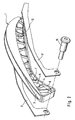
- FIG. 1 shows an inventive, designed as a clamping rail rail 1 with two side plates 2 in a perspective exploded view.
- the rail 1 which consists of plastic, serves for tensioning and guiding an endless traction means, in particular a chain of the control drive of an internal combustion engine.
- the side plates 2 are made of steel and serve to stiffen and reinforce the rail first
- the rail 1 (see also Figure 1d ) has a double-T cross-section with a top flange 3 and a bottom flange 4, which are connected by a central web 5 and vertical ribs 6 on both sides of the web 5.
- a first rib 8 which has no recess 7, serves as a stop for the side plates 2, while the last rib 9 allows unimpeded thermal expansion of the side plates 2 with respect to the rail 1.
- a bore 10 serves to receive a fixing and bearing element 11, which may be formed as a screw or pin. (See also FIG. 2 ). It also serves to attach the rail 1 to the engine and as its pivot bearing.
- FIG. 1a the rail 1 is shown with the side recessed side plates 2 in a perspective view.
- FIG. 1b is a side view of the rail 1 with built-side plates 2 shown.
- the location of some so-called snap hooks 12 is shown, for fixing the side plates 2 in the recesses 7 (see also FIG. 1 ) serve the ribs 6.
- Figure 1c shows the enlarged cross section AA of the rail 1 from FIG. 1b which passes through a rib 6 with snap hook 12. Because of the symmetrical arrangement of the side plates 2, the numbering is provided only on one side.
- ribs 6 are the side plates 2. These preferably have no side clearance in order to achieve optimum stiffening of the plastic rail through the steel side plates 2. Falling out of the side plates 2 from their recesses 7 is prevented by the snap hook 12. These are formed integrally with the rail and project beyond an edge 13 of the recesses 7 of the ribs 6 addition.
- the snap hooks 12 yield elastically to spring back after insertion into an initial and locking position and thus to prevent falling out of the side plates.
- Figure 1d is the cross section BB off FIG. 1b represented, which passes through a rib-free area of the rail 1. Also in this section is numbered because of its symmetry only one side.
- the double-T cross-section with the upper flange 3, the lower flange 4 and the web 5 connecting them are clear to recognize. This also applies to a rib 6 with its side surface 29 and its recess 7 with the side plate. 2
- FIG. 2 is an exploded perspective view of the rail 1 according to FIG. 1 shown, with top flange 3, bottom flange 4, web 5, ribs 6, recess 7 with modified side plates 2 'shown. These are in addition to the snap hook 12 additionally fixed laterally by a fixing and bearing element 11, which also serves to attach and support the rail 1 on the engine.
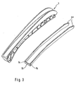
- FIG. 3 shows a rail 1 according to the FIG. 1 and 2 However, with side plates 2 ", which are connected at its screw-near end 14 by a bracket 15 and formed as a one-piece bent part
- This solution is characterized by a cost-effective production and assembly Number of ironing 15 done.
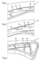
- FIGS. 4 and 5 Details of rails 1 ', 1 "are shown which have first and / or second undercuts 16 and / or 17. These serve as fastening means, behind which a matching part of a first and / or second, displaceable side plate 18 and / or 19 can be inserted is and causes their locking.
- the first undercuts 16 of the rail 1 'protrude as in FIG. 4 represented in the contour of the first displaceable side plates 18 inside.
- matching recesses 21 are provided for the first undercuts 16 at the first undercuts 16 facing side plate edge.
- the second undercuts 17 of the rail 1 "are located outside the contour of the second displaceable side plates 19.
- the side plate edge 20 'of the second displaceable side plates 19 facing the second undercuts 17 has suitable projections 22 and the necessary space for their insertion into the second undercuts 17.
- FIG. 6 shows a detail of a rail 1 '' with a side plate 2 ''. This is in the manufacture of the rail 1 "'with plastic strips 28 encapsulated, which serve as a particularly cost-fastening means for the side plates 2'".
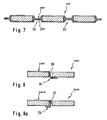
- FIG. 7 is a rail 1 "" with two side plates 2 “” shown schematically.
- the side plates 2 "” are connected to each other at the ends of the rail 1 "” and in intermediate apertures 23 by welding or riveting.
- the connection is designed so that the side plates 2 "” are also in firm connection with the rails 1 "” arranged between the side plates.
- the schematically illustrated rail 1 "" of FIG. 8 has an opening 26 into which a Z-shaped end 24 of a side plate 2 ""'positively engages.
- FIG. 8a a schematically illustrated rail 1 """with an opening 27 in which a U-shaped end 25 of a side plastic 2""" the rail 1 """encloses positively.
- the rails according to the invention are stiff, compact and inexpensive due to the reinforcement by the side plates.
- the different fasteners for the side plates can be combined depending on the application.
Landscapes
- Engineering & Computer Science (AREA)
- General Engineering & Computer Science (AREA)
- Mechanical Engineering (AREA)
- Devices For Conveying Motion By Means Of Endless Flexible Members (AREA)
- Connection Of Plates (AREA)
Claims (10)
- Mécanisme à moyen de traction comprenant au moins un rail (1,1'-1'''''') pour tendre ou guider un moyen de traction sans fin, en particulier une chaîne du mécanisme de commande d'un moteur à combustion interne, le rail (1,1'-1'''''') , qui se compose de plastique et de doublures métalliques, présentant une section transversale en forme de double T avec une courroie supérieure (3) et une courroie inférieure (4), qui sont connectées par une âme centrale (5) et par des nervures (6) qui sont disposées perpendiculairement des deux côtés de l'âme (5), caractérisé en ce que le rail (1,1'-1'''''') présente deux plaques latérales (2, 2'-2'''''', 18, 19) en acier, qui sont incorporées par engagement par correspondance géométrique dans des renfoncements adaptés (7) de surfaces latérales (29) des nervures (6), de préférence sans jeu, et qui sont fixées en position par des moyens de fixation par engagement par correspondance géométrique.
- Mécanisme à moyen de traction selon la revendication 1, caractérisé en ce que l'on prévoit comme moyens de fixation ce qu'on appelle des crochets d'encliquetage (12), qui sont réalisés d'une seule pièce avec le rail (1) et qui sont disposés sur un bord (13) des renfoncements (7) dans le cas d'au moins quelques-unes des nervures (6), les crochets d'encliquetage (12) cédant élastiquement lors de l'insertion des plaques latérales (2) et revenant élastiquement dans la position de départ ou de fixation une fois que les plaques latérales (2) ont atteint leur position de montage.
- Mécanisme à moyen de traction selon la revendication 1, caractérisé en ce qu'un élément de fixation et de support (11), par exemple une vis ou une goupille, qui sont prévus pour la fixation et le support du rail (1) sur le moteur à combustion interne, sert de moyen de fixation supplémentaire pour des plaques latérales (2') de configuration correspondante et pourvues d'un alésage adapté.
- Mécanisme à moyen de traction selon la revendication 1, caractérisé en ce que les deux plaques latérales (2") présentent, en tant que moyen de fixation supplémentaire, au moins un arceau (13) qui permet de les connecter l'une à l'autre à un endroit quelconque et de les réaliser sous forme de pièce cintrée d'une seule pièce.
- Mécanisme à moyen de traction selon la revendication 1, caractérisé en ce que des premières et/ou deuxièmes contre-dépouilles (16 et/ou 17) d'un rail (1',1'') servent de moyens de fixation, derrière lesquelles une partie correspondante d'une première et/ou deuxième plaque latérale déplaçable (18 et/ou 19) peut être insérée.
- Mécanisme à moyen de traction selon la revendication 5, caractérisé en ce que les premières contre-dépouilles (16) du rail (1') pénètrent dans le contour des premières plaques latérales déplaçables (18) et en ce que pour le montage de ces plaques latérales (18) sur leur bord de plaque latérale (20) tourné vers les premières contre-dépouilles (16), on prévoit des évidements adaptés (21) pour le montage des premières contre-dépouilles (16).
- Mécanisme à moyen de traction selon la revendication 5, caractérisé en ce que les deuxièmes contre-dépouilles (17) du rail (1") sont disposées en dehors du contour des deuxièmes plaques latérales déplaçables (19), et en ce que pour leur montage, le bord de plaque latérale (20') tourné vers les deuxièmes contre-dépouilles (17) présente des rebords adaptés (22) et l'espace requis pour leur enfoncement dans les deuxièmes contre-dépouilles (17).
- Mécanisme à moyen de traction selon la revendication 1, caractérisé en ce que pour les moyens de fixation pour les plaques latérales (2'''), celles-ci sont surmoulées lors de la fabrication d'un rail (1"') au moins partiellement avec du plastique.
- Mécanisme à moyen de traction selon la revendication 1, caractérisé en ce que les plaques latérales (2"") sont connectées fixement l'une à l'autre en tant que moyens de fixation aux extrémités d'un rail (1"") et/ou dans des orifices intermédiaires (23) de celui-ci, par exemple par soudage ou rivetage et sont de ce fait également connectées fixement au rail (1'''').
- Mécanisme à moyen de traction selon la revendication 1, caractérisé en ce que les plaques latérales (2""') , (2""") en tant que moyens de fixation présentent au moins une extrémité en forme de Z ou une extrémité en forme de U (24, 25), et en ce que l'extrémité en forme de Z (24) vient en prise par engagement par correspondance géométrique dans une ouverture (26) d'un rail (1""') et en ce que l'extrémité en forme de U (25) entoure le rail (1""") par engagement par correspondance géométrique dans une ouverture (27) de celui-ci.
Applications Claiming Priority (2)
| Application Number | Priority Date | Filing Date | Title |
|---|---|---|---|
| DE102005018901A DE102005018901A1 (de) | 2005-04-22 | 2005-04-22 | Zugmitteltrieb mit zumindest einer Schiene zum Spannen und/oder Führen eines endlosen Zugmittels |
| PCT/EP2006/000931 WO2006114141A1 (fr) | 2005-04-22 | 2006-02-03 | Mecanisme a moyen de traction comportant au moins un rail servant a tendre et/ou guider un moyen de traction sans |
Publications (2)
| Publication Number | Publication Date |
|---|---|
| EP1875107A1 EP1875107A1 (fr) | 2008-01-09 |
| EP1875107B1 true EP1875107B1 (fr) | 2009-07-15 |
Family
ID=36096800
Family Applications (1)
| Application Number | Title | Priority Date | Filing Date |
|---|---|---|---|
| EP06706600A Ceased EP1875107B1 (fr) | 2005-04-22 | 2006-02-03 | Mecanisme a moyen de traction comportant au moins un rail servant a tendre et/ou guider un moyen de traction sans |
Country Status (5)
| Country | Link |
|---|---|
| US (1) | US20080153643A1 (fr) |
| EP (1) | EP1875107B1 (fr) |
| KR (1) | KR20070121733A (fr) |
| DE (2) | DE102005018901A1 (fr) |
| WO (1) | WO2006114141A1 (fr) |
Families Citing this family (12)
| Publication number | Priority date | Publication date | Assignee | Title |
|---|---|---|---|---|
| DE102007015677A1 (de) * | 2007-03-31 | 2008-10-02 | Schaeffler Kg | Versteifung von Bauteilen für Zugmittelführungen |
| DE102009023825A1 (de) * | 2009-06-04 | 2010-12-09 | Schaeffler Technologies Gmbh & Co. Kg | Führungsschiene |
| DE102011006306A1 (de) * | 2011-03-29 | 2012-10-04 | Bayerische Motoren Werke Aktiengesellschaft | Führungsbauteil aus Kunststoff zum Führen einer Endloskette eines Kettentriebs |
| JP2014145398A (ja) * | 2013-01-28 | 2014-08-14 | Tsubakimoto Chain Co | チェーンガイド |
| JP5848277B2 (ja) * | 2013-03-12 | 2016-01-27 | 株式会社椿本チエイン | チェーンガイド |
| DE102013004456B3 (de) * | 2013-03-14 | 2014-09-18 | Iwis Motorsysteme Gmbh & Co. Kg | Spannschiene mit federndem Aufdrückbereich |
| JP5980177B2 (ja) * | 2013-07-22 | 2016-08-31 | 株式会社椿本チエイン | チェーンガイド |
| DE102013216806A1 (de) * | 2013-08-23 | 2015-02-26 | Schaeffler Technologies Gmbh & Co. Kg | Spann- oder Führungsschiene für einen Zugmitteltrieb an einem Verbrennungsmotor eines Fahrzeugs |
| DE102013224007A1 (de) * | 2013-11-25 | 2015-05-28 | Schaeffler Technologies AG & Co. KG | Spannschiene sowie Zugmitteltrieb mit derartiger Spannschiene |
| JP6408974B2 (ja) * | 2015-10-21 | 2018-10-17 | 株式会社椿本チエイン | チェーンガイド |
| JP6324359B2 (ja) * | 2015-10-21 | 2018-05-16 | 株式会社椿本チエイン | チェーンガイド |
| JP6823261B2 (ja) * | 2017-02-24 | 2021-02-03 | 株式会社椿本チエイン | チェーンガイド |
Family Cites Families (28)
| Publication number | Priority date | Publication date | Assignee | Title |
|---|---|---|---|---|
| GB1172716A (en) * | 1967-05-31 | 1969-12-03 | Borge Warner Ltd | Chain Tensioner. |
| US4846894A (en) * | 1984-05-23 | 1989-07-11 | J. M. Huber Corporation | Air recuperator cleaner |
| US4798562A (en) * | 1986-01-22 | 1989-01-17 | Moxee Innovations Corporation | Tensioning device for flexible drive element |
| US4826468A (en) * | 1987-11-18 | 1989-05-02 | Klifa Fahrzeugteile Gmbh & Co. | Chain tensioner |
| JPH0736201Y2 (ja) * | 1989-05-31 | 1995-08-16 | 株式会社椿本チエイン | 合成樹脂製シューを具えたチェーンガイドレール |
| US4921472A (en) * | 1989-06-12 | 1990-05-01 | Borg-Warner Automotive Transmission & Engine Components Corporation | Chain tensioner |
| US5012943A (en) * | 1990-06-07 | 1991-05-07 | Nick King | Segmented interlocking tracks produced by injection molds |
| JP2519476Y2 (ja) * | 1991-04-11 | 1996-12-04 | 株式会社椿本チエイン | テンショナレバーのシューの浮上り防止構造 |
| JPH089476Y2 (ja) * | 1991-11-07 | 1996-03-21 | 株式会社椿本チエイン | チェーンガイドのアームとシューの一体化構造 |
| US5352189A (en) * | 1992-02-19 | 1994-10-04 | Tecnol Medical Products, Inc. | Ankle brace walker |
| DE29602917U1 (de) * | 1996-02-19 | 1997-06-19 | Joh. Winklhofer & Söhne GmbH und Co KG, 81369 München | Spann- oder Führungsschiene für einen Kettentrieb |
| US5711732A (en) * | 1996-03-06 | 1998-01-27 | Cloyes Gear And Products, Inc. | Chain tensioner apparatus and method |
| US5853341A (en) * | 1997-03-26 | 1998-12-29 | Borg-Warner Automotive, Inc. | Laminated chain tensioner arms or guides |
| IT1290499B1 (it) * | 1997-03-28 | 1998-12-04 | Borg Warner Automotive | Tenditore per catene,con pattino in materia plastica e molla/e a lamina ad estremita' ricurve |
| JP3755061B2 (ja) * | 1998-01-09 | 2006-03-15 | 大同工業株式会社 | テンショナーレバー |
| JP2000230611A (ja) * | 1999-02-15 | 2000-08-22 | Borg Warner Automotive Kk | ブレードテンショナ |
| DE19927067A1 (de) * | 1999-06-15 | 2000-12-21 | Bosch Gmbh Robert | Platine |
| US6612952B1 (en) * | 1999-10-28 | 2003-09-02 | Borgwarner Inc. | Blade tensioner having spring blade cantilevered from distal end of arm |
| US6302816B1 (en) * | 2000-03-07 | 2001-10-16 | Borgwarner Inc. | Chain guide or tensioner arm with sheet metal bracket and alternating tabs |
| US6554728B2 (en) * | 2000-10-05 | 2003-04-29 | Borgwarner, Inc. | Fastenerless chain snubber |
| JP3338436B1 (ja) * | 2001-10-02 | 2002-10-28 | 株式会社椿本チエイン | 伝動装置用摺接ガイド |
| JP3516940B2 (ja) * | 2001-10-23 | 2004-04-05 | 株式会社椿本チエイン | 伝動装置用プラスチック製可動ガイド |
| JP3359339B1 (ja) * | 2002-01-22 | 2002-12-24 | 株式会社椿本チエイン | 伝動装置用摺接ガイド |
| US6913552B2 (en) * | 2002-01-23 | 2005-07-05 | Cloyes Gear And Products, Inc. | Snap-fit chain guide with saw-tooth fixing feature |
| JP3359340B1 (ja) * | 2002-01-23 | 2002-12-24 | 株式会社椿本チエイン | 伝動装置用可動ガイド |
| JP3357043B1 (ja) * | 2002-01-25 | 2002-12-16 | 株式会社椿本チエイン | 伝動装置用合成樹脂ガイド |
| JP2005048931A (ja) * | 2003-07-31 | 2005-02-24 | Tsubakimoto Chain Co | 伝動装置用レバー |
| US6979009B2 (en) * | 2004-02-26 | 2005-12-27 | Shimano Inc. | Motorized bicycle derailleur assembly |
-
2005
- 2005-04-22 DE DE102005018901A patent/DE102005018901A1/de not_active Withdrawn
-
2006
- 2006-02-03 WO PCT/EP2006/000931 patent/WO2006114141A1/fr not_active Ceased
- 2006-02-03 US US11/911,910 patent/US20080153643A1/en not_active Abandoned
- 2006-02-03 EP EP06706600A patent/EP1875107B1/fr not_active Ceased
- 2006-02-03 DE DE502006004240T patent/DE502006004240D1/de not_active Expired - Lifetime
- 2006-02-03 KR KR1020077023260A patent/KR20070121733A/ko not_active Withdrawn
Also Published As
| Publication number | Publication date |
|---|---|
| US20080153643A1 (en) | 2008-06-26 |
| DE102005018901A1 (de) | 2006-11-16 |
| KR20070121733A (ko) | 2007-12-27 |
| DE502006004240D1 (de) | 2009-08-27 |
| EP1875107A1 (fr) | 2008-01-09 |
| WO2006114141A1 (fr) | 2006-11-02 |
Similar Documents
| Publication | Publication Date | Title |
|---|---|---|
| EP1383967B1 (fr) | Couvercle pour un systeme d'ecoulement des eaux | |
| EP2971354B1 (fr) | Fixation de rails comprenant un raccordement par clipsage entre la plaque de guidage et la plaque de base | |
| DE19820699C1 (de) | Führungskulisse für Schiebedeckel an Schiebehebedachkonstruktionen für Kraftfahrzeuge | |
| EP1875107B1 (fr) | Mecanisme a moyen de traction comportant au moins un rail servant a tendre et/ou guider un moyen de traction sans | |
| DE2431425C2 (de) | Spannschiene für Kettenantriebe | |
| EP1729387A2 (fr) | Dispositif de fixation d'une ligne | |
| DE69923646T2 (de) | Fahrzeugtür mit abgedichtem Ausrüstungsmodul und entfernbarem Medaillon in der Innenverkleidung | |
| EP1636439A1 (fr) | Dispositif d'evacuation des eaux de ruissellement | |
| DE102014203272A1 (de) | Kettenführung | |
| DE3328998C2 (de) | Befestigungsanordnung für ein Wischerblatt und dabei verwendbarer Verriegelungseinsatz | |
| EP1743992A2 (fr) | Dispositif de montage d'une clôture avec poteau de clôture et support | |
| DE102014202959A1 (de) | Kettenführung | |
| DE10333077A1 (de) | Spann- oder Führungsschiene mit am Tragkörper vorstehendem Rastmittel | |
| DE19511788C5 (de) | Lösbare Verriegelungsvorrichtung für einen befahrbaren Rost einer Entwässerungsrinne | |
| DE102004019158A1 (de) | Wischblatt | |
| DE3326763A1 (de) | Tuerband | |
| DE19820336A1 (de) | Armlehne für einen Kraftfahrzeugsitz | |
| DE20302195U1 (de) | Entwässerungsvorrichtung | |
| EP1780345B1 (fr) | Raccord pour profilés en forme de U et ensemble de raccordement | |
| WO2008049686A1 (fr) | Balai d'essuie-glace | |
| DE102007017441B3 (de) | Treibstangenanordnung mit mindestens einer Treibstange und mindestens einem Treibstangenführungselement | |
| EP0649361B1 (fr) | Agrafeuse | |
| DE202009010957U1 (de) | Montageaufbau eines teleskopischen Schutzdeckels | |
| DE8002883U1 (de) | Kunststoff-Clip zur Befestigung von Verkleidungen in Kraftfahrzeugen o.dgl | |
| DE19925559C1 (de) | Kette für Spannrahmentrockner |
Legal Events
| Date | Code | Title | Description |
|---|---|---|---|
| PUAI | Public reference made under article 153(3) epc to a published international application that has entered the european phase |
Free format text: ORIGINAL CODE: 0009012 |
|
| 17P | Request for examination filed |
Effective date: 20071122 |
|
| AK | Designated contracting states |
Kind code of ref document: A1 Designated state(s): DE FR IT |
|
| 17Q | First examination report despatched |
Effective date: 20080225 |
|
| DAX | Request for extension of the european patent (deleted) | ||
| RBV | Designated contracting states (corrected) |
Designated state(s): DE FR IT |
|
| GRAP | Despatch of communication of intention to grant a patent |
Free format text: ORIGINAL CODE: EPIDOSNIGR1 |
|
| GRAS | Grant fee paid |
Free format text: ORIGINAL CODE: EPIDOSNIGR3 |
|
| GRAA | (expected) grant |
Free format text: ORIGINAL CODE: 0009210 |
|
| AK | Designated contracting states |
Kind code of ref document: B1 Designated state(s): DE FR IT |
|
| REF | Corresponds to: |
Ref document number: 502006004240 Country of ref document: DE Date of ref document: 20090827 Kind code of ref document: P |
|
| RAP2 | Party data changed (patent owner data changed or rights of a patent transferred) |
Owner name: SCHAEFFLER TECHNOLOGIES GMBH & CO. KG |
|
| PLBE | No opposition filed within time limit |
Free format text: ORIGINAL CODE: 0009261 |
|
| STAA | Information on the status of an ep patent application or granted ep patent |
Free format text: STATUS: NO OPPOSITION FILED WITHIN TIME LIMIT |
|
| 26N | No opposition filed |
Effective date: 20100416 |
|
| REG | Reference to a national code |
Ref country code: DE Ref legal event code: R081 Ref document number: 502006004240 Country of ref document: DE Owner name: SCHAEFFLER TECHNOLOGIES AG & CO. KG, DE Free format text: FORMER OWNER: SCHAEFFLER TECHNOLOGIES GMBH & CO. KG, 91074 HERZOGENAURACH, DE Effective date: 20120828 Ref country code: DE Ref legal event code: R081 Ref document number: 502006004240 Country of ref document: DE Owner name: SCHAEFFLER TECHNOLOGIES GMBH & CO. KG, DE Free format text: FORMER OWNER: SCHAEFFLER TECHNOLOGIES GMBH & CO. KG, 91074 HERZOGENAURACH, DE Effective date: 20120828 |
|
| REG | Reference to a national code |
Ref country code: DE Ref legal event code: R081 Ref document number: 502006004240 Country of ref document: DE Owner name: SCHAEFFLER TECHNOLOGIES AG & CO. KG, DE Free format text: FORMER OWNER: SCHAEFFLER TECHNOLOGIES AG & CO. KG, 91074 HERZOGENAURACH, DE Effective date: 20140214 Ref country code: DE Ref legal event code: R081 Ref document number: 502006004240 Country of ref document: DE Owner name: SCHAEFFLER TECHNOLOGIES GMBH & CO. KG, DE Free format text: FORMER OWNER: SCHAEFFLER TECHNOLOGIES AG & CO. KG, 91074 HERZOGENAURACH, DE Effective date: 20140214 |
|
| REG | Reference to a national code |
Ref country code: DE Ref legal event code: R081 Ref document number: 502006004240 Country of ref document: DE Owner name: SCHAEFFLER TECHNOLOGIES AG & CO. KG, DE Free format text: FORMER OWNER: SCHAEFFLER TECHNOLOGIES GMBH & CO. KG, 91074 HERZOGENAURACH, DE Effective date: 20150223 |
|
| REG | Reference to a national code |
Ref country code: FR Ref legal event code: PLFP Year of fee payment: 11 |
|
| REG | Reference to a national code |
Ref country code: FR Ref legal event code: PLFP Year of fee payment: 12 |
|
| REG | Reference to a national code |
Ref country code: FR Ref legal event code: PLFP Year of fee payment: 13 |
|
| PGFP | Annual fee paid to national office [announced via postgrant information from national office to epo] |
Ref country code: IT Payment date: 20180221 Year of fee payment: 13 Ref country code: FR Payment date: 20180226 Year of fee payment: 13 |
|
| PGFP | Annual fee paid to national office [announced via postgrant information from national office to epo] |
Ref country code: DE Payment date: 20180430 Year of fee payment: 13 |
|
| REG | Reference to a national code |
Ref country code: DE Ref legal event code: R119 Ref document number: 502006004240 Country of ref document: DE |
|
| PG25 | Lapsed in a contracting state [announced via postgrant information from national office to epo] |
Ref country code: DE Free format text: LAPSE BECAUSE OF NON-PAYMENT OF DUE FEES Effective date: 20190903 |
|
| PG25 | Lapsed in a contracting state [announced via postgrant information from national office to epo] |
Ref country code: FR Free format text: LAPSE BECAUSE OF NON-PAYMENT OF DUE FEES Effective date: 20190228 Ref country code: IT Free format text: LAPSE BECAUSE OF NON-PAYMENT OF DUE FEES Effective date: 20190203 |
|
| P01 | Opt-out of the competence of the unified patent court (upc) registered |
Effective date: 20230522 |