EP1875794B1 - Dispositif de ramassage pour produits agricoles comportant une forme de branche mince et longue tels que l'herbe, la paille, les légumineux et autres produits similaires. - Google Patents
Dispositif de ramassage pour produits agricoles comportant une forme de branche mince et longue tels que l'herbe, la paille, les légumineux et autres produits similaires. Download PDFInfo
- Publication number
- EP1875794B1 EP1875794B1 EP07008618A EP07008618A EP1875794B1 EP 1875794 B1 EP1875794 B1 EP 1875794B1 EP 07008618 A EP07008618 A EP 07008618A EP 07008618 A EP07008618 A EP 07008618A EP 1875794 B1 EP1875794 B1 EP 1875794B1
- Authority
- EP
- European Patent Office
- Prior art keywords
- pick
- transport
- zone
- prongs
- prong
- Prior art date
- Legal status (The legal status is an assumption and is not a legal conclusion. Google has not performed a legal analysis and makes no representation as to the accuracy of the status listed.)
- Active
Links
- 0 CCIC(*)N(C(C)I)IC Chemical compound CCIC(*)N(C(C)I)IC 0.000 description 1
Images


Classifications
-
- A—HUMAN NECESSITIES
- A01—AGRICULTURE; FORESTRY; ANIMAL HUSBANDRY; HUNTING; TRAPPING; FISHING
- A01D—HARVESTING; MOWING
- A01D89/00—Pick-ups for loaders, chaff-cutters, balers, field-threshers, or the like, i.e. attachments for picking-up hay or the like field crops
- A01D89/001—Pick-up systems
- A01D89/002—Rotors
Definitions
- the subject of this invention is a pick up device for agricultural products having a thin and long-limbed shape such as grass, straw, leguminous and similar products.
- Pick up devices are usually used for picking up from the ground, grass, straw, hay (which have been previously cut by other machines) or for picking up leguminous; anyway for picking up similar agricultural products (generally vegetables), having a long-limbed shape.
- tractive unit like a tractor or a self-propelled agricultural machine
- Common pick up devices have a preferential direction of development which, during use, is kept transversal to the shifting direction of the tractive unit.
- these pick up devices use and are combined to a plurality of pick up elements which are moved by a driving system.
- the driving system is generally operated by a universal joint or the like which, through a power take-off, takes driving power from the tractive unit engine.
- Each pick up element is in turn equipped with one or more prongs placed side by side.
- the pick up elements (and the respective prongs) are generally arranged around the preferential direction of development along rows, which are parallel to the preferential direction of development itself.
- Each pick up element (and its prongs) is moved by the driving system along a closed trajectory which surrounds the preferential direction of development.
- the prongs are straight elements, one end of which is hooked (directly or through some parts of the pick up element) to the driving system, while the opposite end is free.
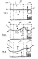
- every prong can be divided into three zones: a zone of product taking up, which corresponds to the free end and is the zone which comes first into contact with the product during harvesting; a zone of product transport, consecutive to the taking up zone, having a size larger than the latter; an hooking zone, consecutive to the transport zone, intended for hooking to the driving system.
- the transport zone is a straight segment.
- the taking up zone is also a straight segment which can lie on the same lying straight line of the transport zone or it can be slightly inclined with respect to the latter.
- This trajectory section corresponds to the lifting of the agricultural product from the ground and to the transport of it, through the prongs, up to the product unloading point which is placed along the closed trajectory itself.
- This plurality of bands defines a covering surface of the driving system, which prevents the agricultural product from falling inside during transport. Every band is placed between two prongs which are consecutive to each other along the preferential direction of development. Between two consecutive bands a space is provided to let each prong freely move along the closed trajectory.
- Prongs stretch out towards outside the space delimited by the covering surface, the lying straight line of the transport zone being substantially perpendicular to the covering surface itself.
- a row of prongs acts as a rotating rake, which comes first into contact with the product through the taking up zone and lifts it up. Then the product is intercepted by the transport zone which carries it up to a point where it has to be unloaded.
- Document GB-A-1 196 311 discloses a device for picking up lump and fibrous materials (including strawy mass and the like), which comprises a pick up assembly having fork members for picking up the material, each fork member comprising a plurality of teeth which are spaced along a tube hinged at a rotatable support means.
- a plurality of discharge guides in the form of bands are fixed at the structure of the pick-up device, each guide being interposed between two consecutive teeth of the fork members. Rotation of the support means in a first direction makes each tooth move between two consecutive discharge guides along a closed trajectory around the line of development of the device.
- each tooth does not rotate around the point where it is hinged at the rotatable support means.
- the tooth is rotated around said hinge point by a fork reversing arrangement, to make the tooth disappear in the space delimited by the guides during the motion along the remaining part of the closed curve from the discharge point to the pick-up point.
- the teeth have a curved shape which is turned towards the discharge point when the teeth move along the first part of the closed trajectory.
- the present invention aims at removing the above mentioned drawbacks, providing a pick up device for agricultural products having a thin and long-limbed shape such as grass, straw, leguminous and similar products that, thanks to the configuration of the pick up elements and properly mounting the pick up elements, allows an optimum unloading of the product and avoids product infiltration in the area where the driving system is placed.
- a pick up device for agricultural products having a thin and long-limbed shape such as grass, straw, leguminous and similar products which has structural and functional features in accordance with the independent claim herein, further embodiments of the same being described by the corresponding dependent claims herein.
- the hooking zone 102 is intended for hooking to a pick up device 2, directly or by means of some hooking parts of the pick up element 1 .
- the development line 11 defines a holding and transport concavity 112 of agricultural products.
- the development line 11 may be curvilinear without any straight segment.
- at least part of the holding and transport concavity 112 is defined by a broken line (see figure 1 , where this holds for the whole portion of the development line 11 which defines the holding and transport concavity 112).
- the broken line is defined by a first 113 and a second 114 segment. Any way the broken line may be defined also by more than two segments. At least two of the segments forming the broken line may be joined together by a curved portion (as shown in figure 1 ).
- the meeting point between the first 113 and the second 114 segment is less far from the hooking zone 102 than from the taking up zone 100.
- the pick up element 1 may comprise two or more identical prongs 10 placed side by side. Such prongs 10 may be made integral to one another by (not illustrated) connecting means provided with hooking parts to a pick up element 2.
- the specific shape of the prong 10 in the hooking area 102 is not essential for the invention ultimate aim: this shape is generally determined by the internal features of the pick up device 2 whereon the pick up element 1 shall be mounted and can contemplate (as partly illustrated in the figures) spiral parts working as springs to allow an elastic strain of pick up elements 1 during operation.
- a pick up device 2 for agricultural products having a thin and long-limbed shape such as grass, straw, leguminous and similar products, of the type which can be dragged by a tractive unit and has a preferential direction 20 of development which, during use, is kept transversal to the shifting direction of the tractive unit, comprises a plurality of pick up elements 1 of agricultural products, each of them provided with at least one long-limbed pick up prong 10.
- the pick up device 2 comprises a driving system 21 of every pick up element 1 along a closed trajectory surrounding the preferential direction 20 of development, the closed trajectory comprising a transport segment of the agricultural product between a taking up point of the product from the ground by the long-limbed prongs 10 and a release point of the agricultural product by the long-limbed prongs 10, once arrived in correspondence with the release point the prong 10 not having a transport function of the agricultural product any more.
- the pick up device 2 comprises a plurality of bands 22 placed side by side, fixed to the driving system 21 with respect to the pick up elements 1 and surrounding the preferential direction 20 of development at least in correspondence with the transport segment of the closed trajectory.
- the plurality of bands 22 placed side by side defines a surface 23 of at least partial covering of the driving system 21.
- Each band is placed between two long-limbed prongs 10 which are consecutive to each other along the preferential direction 20 of development and between two consecutive bands 22 a space is provided to let each long-limbed prong freely move along the preferential direction 20 of development.
- the pick up elements 1 are pick up elements 1 according to the invention and made according to any one of the embodiments and possibilities previously described in the description of pick up elements 1 according to the invention.
- the pick up device 2 according to the invention during the motion of the prongs 10 along the whole of the transport segment of the closed trajectory:
- the angle A is greater than 110 degrees. Opportunely, the angle A is smaller than 170 degrees. Preferably the angle A is comprised between 120 and 140 degrees.
- the invention has some important advantages.
Landscapes
- Life Sciences & Earth Sciences (AREA)
- Environmental Sciences (AREA)
- Pretreatment Of Seeds And Plants (AREA)
- Apparatuses For Bulk Treatment Of Fruits And Vegetables And Apparatuses For Preparing Feeds (AREA)
- Transplanting Machines (AREA)
- Supports For Plants (AREA)
- Catching Or Destruction (AREA)
- Sorting Of Articles (AREA)
Claims (9)
- Dispositif de ramassage (2) pour produits agricoles comportant une forme de branche mince et longue tels que l'herbe, la paille, les légumineux et produits similaires, du type pouvant être tracté par une unité de traction et présentant une direction préférentielle (20) de développement qui, en opération, est maintenue transversale à la direction de déplacement de l'unité de traction, comprenant:- une pluralité d'éléments de ramassage (1) de produits agricoles, chacun desquels étant pourvu d'au moins un fourchon longiligne de ramassage (10);- un système (21) de déplacement de chaque élément de ramassage (1) le long d'une trajectoire fermée qui entoure la direction préférentielle (20) de développement, la trajectoire fermée comprenant une zone de transport du produit agricole entre un point de prélèvement du produit du sol par les fourchons longilignes (10) et un point de libération du produit agricole par les fourchons longilignes (10), les fourchons (10) n'ayant plus de fonction de transport du produit agricole lorsqu'ils arrivent en correspondance du point de libération;- une pluralité de bandes (22) placées côte-à-côte, fixées au système de déplacement (21) par rapport aux éléments de ramassage (1) et entourant la direction préférentielle (20) de développement au moins en correspondance de la zone de transport de la trajectoire fermée pour définir une surface (23) de couverture au moins partielle du système de déplacement (21), chaque bande étant placée entre deux fourchons longilignes (10) consécutifs entre eux le long de la direction préférentielle (20) de développement, un espace étant prévu entre deux bandes (22) consécutives pour laisser chaque fourchon longiligne (10) se déplacer librement autour de la direction préférentielle (20) de développement;dans lequel le fourchon (10) de chaque élément de ramassage (1) se développe le long d'une ligne de développement (11) entre une première et une seconde extrémité (110, 111), le fourchon (10) étant idéalement divisé le long de la ligne de développement (11) en:- une zone (100) de prélèvement des produits agricoles du sol comprenant la première extrémité (110);- une zone (101) de transport des produits agricoles consécutive à la zone (100) de prélèvement, dans la zone de transport (101) la ligne de développement (11) définissant une concavité (112) de retenue et de transport des produits agricoles;- une zone (102) d'accrochage consécutive à la zone de transport (101), comprenant la seconde extrémité (111) et étant destinée à l'accrochage de l'élément de ramassage (1) au dispositif de ramassage (2), directement ou au moyen de parties d'accrochage de l'élément de ramassage (1); et dans lequel, pendant le déplacement des fourchons (10) le long de toute la zone de transport de la trajectoire fermée, la zone d'accrochage (102) de chaque fourchon (10) reste à l'intérieur de la surface (23) de couverture au moins partielle du système de déplacement (21);caractérisé en ce que, pendant le déplacement des fourchons (10) le long de toute la zone de transport de la trajectoire fermée:- la concavité de retenue et de transport (112) est orientée vers la même direction (116) de mouvement des fourchons (10) le long de la trajectoire fermée et est inclinée par rapport aux bandes (22);- la ligne de développement (11) de chaque fourchon (10) croise la surface (23) de couverture au moins partielle en un point (24) d'intersection qui correspond à un point de la zone de transport (101) du fourchon (10);- la tangente (115) à la ligne de développement (11) de chaque fourchon (10) en correspondance du point d'intersection (24) et la tangente (220) à une ligne de développement (221) de chaque bande (22) adjacente à celle-ci en correspondance du même point d'intersection (24) forment entre elles, à l'extérieur de la surface (23) de couverture au moins partielle et sur le côté vers lequel la concavité de transport (112) est orientée, un angle (A) supérieur à 90 degrés; de manière à ce que, pendant le déplacement du fourchon (10) le long de la zone de transport de la trajectoire fermée du point de prélèvement au point de libération, le produit agricole tende à s'éloigner des bandes (22) et à s'accumuler dans la concavité de transport (112), en facilitant la libération du produit agricole des fourchons (10) en correspondance du point de libération.
- Dispositif de ramassage (2) selon la revendication 1,
caractérisé en ce que l'angle (A) est supérieur à 110 degrés. - Dispositif de ramassage (2) selon la revendication 1, caractérisé en ce que l'angle (A) est compris entre 120 et 140 degrés.
- Dispositif de ramassage (2) selon la revendication 1,
caractérisé en ce que l'angle (A) est inférieur à 170 degrés. - Dispositif de ramassage (2) selon l'une quelconque des revendications précédentes, caractérisé en ce qu'au moins une partie de la concavité de retenue et de transport (112) est définie par une ligne interrompue.
- Dispositif de ramassage (2) selon la revendication 5, caractérisé en ce que la ligne interrompue est définie par un premier (113) et un second (114) segment.
- Dispositif de ramassage (2) selon la revendication 6,
caractérisé en ce que le point de rencontre entre le premier (113) et le second (114) segment est moins éloigné de la zone d'accrochage (102) que de la zone de prélèvement (100). - Dispositif de ramassage (2) selon l'une quelconque des revendications 5 à 7, caractérisé en ce qu'au moins deux des segments formant la ligne interrompue sont joints entre eux par une partie courbée.
- Dispositif de ramassage (2) selon l'une quelconque des revendications précédentes, caractérisé en ce qu'il comprend deux ou plus fourchons (10) identiques placés côte-à-côte.
Applications Claiming Priority (1)
| Application Number | Priority Date | Filing Date | Title |
|---|---|---|---|
| IT000046A ITRN20060046A1 (it) | 2006-07-03 | 2006-07-03 | Elemento di raccolta di prodotti agricoli di forma esile e longilinea, come erba,paglia, leguminose e simili e dispositivo di raccolta utilizzante il medesimo |
Publications (2)
| Publication Number | Publication Date |
|---|---|
| EP1875794A1 EP1875794A1 (fr) | 2008-01-09 |
| EP1875794B1 true EP1875794B1 (fr) | 2009-10-14 |
Family
ID=38198219
Family Applications (1)
| Application Number | Title | Priority Date | Filing Date |
|---|---|---|---|
| EP07008618A Active EP1875794B1 (fr) | 2006-07-03 | 2007-04-27 | Dispositif de ramassage pour produits agricoles comportant une forme de branche mince et longue tels que l'herbe, la paille, les légumineux et autres produits similaires. |
Country Status (5)
| Country | Link |
|---|---|
| US (1) | US20080000212A1 (fr) |
| EP (1) | EP1875794B1 (fr) |
| AT (1) | ATE445313T1 (fr) |
| DE (1) | DE602007002748D1 (fr) |
| IT (1) | ITRN20060046A1 (fr) |
Families Citing this family (6)
| Publication number | Priority date | Publication date | Assignee | Title |
|---|---|---|---|---|
| CN102334409A (zh) * | 2010-07-19 | 2012-02-01 | 中国农业机械化科学研究院 | 捡拾输送台及包含其的秸秆收获机 |
| US8181435B1 (en) * | 2011-11-15 | 2012-05-22 | Cnh America Llc | Pick-up tine dividers |
| US9089093B2 (en) * | 2013-03-12 | 2015-07-28 | Agco Corporation | Spring tine with integrated relief section |
| NL2015256B1 (en) * | 2015-06-22 | 2017-02-15 | Forage Innovations Bv | Tine mounting pads. |
| RU194973U1 (ru) * | 2019-04-03 | 2020-01-09 | Федеральное государственное автономное образовательное учреждение высшего образования "Уральский федеральный университет имени первого Президента России Б.Н. Ельцина" | Подбирающий палец транспортерного подборщика комбайна |
| SE2351054A1 (en) * | 2023-09-08 | 2025-03-09 | Vaederstad Holding Ab | Agricultural implements comprising a straw harrow |
Family Cites Families (36)
| Publication number | Priority date | Publication date | Assignee | Title |
|---|---|---|---|---|
| US1631455A (en) * | 1924-10-07 | 1927-06-07 | Bamford Joseph | Tine for haymaking and like machinery |
| US1776736A (en) * | 1928-03-22 | 1930-09-23 | Carl R Livermon | Stripper tooth for thrashing machines |
| US2527887A (en) * | 1947-04-18 | 1950-10-31 | Fmc Corp | Pickup mechanism for harvesting machines |
| US2682743A (en) * | 1952-03-17 | 1954-07-06 | Int Harvester Co | Harvester pickup |
| NL100758C (fr) * | 1958-05-27 | |||
| US3127727A (en) * | 1960-07-12 | 1964-04-07 | Lely Nv C Van Der | Tedders |
| US3099347A (en) * | 1961-02-23 | 1963-07-30 | Case Co J I | Means for mounting spring fingers |
| US3236038A (en) * | 1964-04-08 | 1966-02-22 | Lauren W Gates | Rotary pickup for tomato harvester |
| US3295302A (en) * | 1965-05-24 | 1967-01-03 | Robert E Lee | Grain pickup with rubber teeth |
| DE1582466A1 (de) * | 1966-04-24 | 1970-07-02 | Uk Nii Selskokhozyaistvennogo | Sammel- und Verladeeinrichtung fuer Stueckgut und Faserstoffe |
| US3771303A (en) * | 1966-08-31 | 1973-11-13 | Lely Nv C Van Der | Device for working crop lying on the ground |
| US3613345A (en) * | 1969-09-30 | 1971-10-19 | Deere & Co | Crop-handling means and stripper therefor |
| US3713283A (en) * | 1972-02-09 | 1973-01-30 | Int Harvester Co | Tine guiding device for crop pick-up |
| US3766725A (en) * | 1972-04-27 | 1973-10-23 | P Marsh | Farm crop handling apparatus |
| NL157484B (nl) * | 1976-03-26 | 1978-08-15 | Zweegers P | Verende tand voor een landbouwwerktuig. |
| US4161859A (en) * | 1977-06-09 | 1979-07-24 | International Harvester Company | Crop pickup device |
| US4182102A (en) * | 1977-09-29 | 1980-01-08 | Hesston Corporation | Crop pickup assembly |
| NL177376C (nl) * | 1979-03-30 | 1985-09-16 | Lely Nv C Van Der | Inrichting voor het zijwaarts verplaatsen van op de grond liggend gewas. |
| US4297833A (en) * | 1979-10-11 | 1981-11-03 | Hesston Corporation | Crop pickup with outboard cam control |
| US4437296A (en) * | 1979-12-31 | 1984-03-20 | Victory Equipment Limited | Draper pick-up tine |
| US4366898A (en) * | 1980-04-21 | 1983-01-04 | Bobrysheva Ljubov V | Conveyor of a farm machine pickup |
| FR2481054A1 (fr) * | 1980-04-24 | 1981-10-30 | Carree Francis | Machine pour faner, andainer, eparpiller, etaler et charger |
| US4495755A (en) * | 1983-07-19 | 1985-01-29 | The Goodyear Tire & Rubber Company | Conveyor for a combine harvester |
| US4495756A (en) * | 1983-08-15 | 1985-01-29 | Sperry Corporation | Pickup attachment for harvesting machines |
| US4751811A (en) * | 1986-03-14 | 1988-06-21 | The Goodyear Tire & Rubber Company | Conveyor for a combine harvester |
| US5065570A (en) * | 1988-02-24 | 1991-11-19 | Kuehn Melvin C | Bi-fold hay rake system |
| US4929904A (en) * | 1989-07-24 | 1990-05-29 | Ford New Holland, Inc. | Moisture sensing apparatus with movable probe in combination with an agricultural baler having a pickup |
| US5493853A (en) * | 1993-10-26 | 1996-02-27 | Tonutti S.P.A. | Draw bar bifold hay rake |
| US5842335A (en) * | 1996-10-04 | 1998-12-01 | Hay & Forage Industries | Bottom loading, in-line square baler with dual purpose stuffer |
| US5918452A (en) * | 1997-08-01 | 1999-07-06 | Kelderman; Gary L. | Foldable, pull-type, V-rake apparatus |
| DE29720527U1 (de) * | 1997-09-15 | 1998-01-29 | Hermann Lohmann Maschinenfabrik Westkirchen, 59320 Ennigerloh | Aufnahmeeinheit für Erntegut |
| US5960620A (en) * | 1998-02-11 | 1999-10-05 | Ogden Metalworks, Inc. | Rake arm assembly |
| US6314710B1 (en) * | 1998-08-31 | 2001-11-13 | Tonutti S.P.A. | V-rake with windrow width adjustment |
| US6338236B1 (en) * | 2000-06-14 | 2002-01-15 | Henry Rodriguez | Mechanized harvesting machine with rotating picking elements |
| US6715275B1 (en) * | 2000-06-22 | 2004-04-06 | Vermeer Manufacturing Company | Hay rake twin tooth with continuous camber and lost-motion activation and a rake wheel using the same |
| US6948300B1 (en) * | 2003-07-30 | 2005-09-27 | Vermeer Manufacturing Company | Wide pickup header for a round baler |
-
2006
- 2006-07-03 IT IT000046A patent/ITRN20060046A1/it unknown
-
2007
- 2007-04-27 EP EP07008618A patent/EP1875794B1/fr active Active
- 2007-04-27 DE DE602007002748T patent/DE602007002748D1/de active Active
- 2007-04-27 AT AT07008618T patent/ATE445313T1/de active
- 2007-06-25 US US11/768,080 patent/US20080000212A1/en not_active Abandoned
Also Published As
| Publication number | Publication date |
|---|---|
| DE602007002748D1 (de) | 2009-11-26 |
| EP1875794A1 (fr) | 2008-01-09 |
| US20080000212A1 (en) | 2008-01-03 |
| ITRN20060046A1 (it) | 2008-01-04 |
| ATE445313T1 (de) | 2009-10-15 |
Similar Documents
| Publication | Publication Date | Title |
|---|---|---|
| EP1875794B1 (fr) | Dispositif de ramassage pour produits agricoles comportant une forme de branche mince et longue tels que l'herbe, la paille, les légumineux et autres produits similaires. | |
| EP1327384B1 (fr) | Outil pour le traitement de récolte | |
| US6948300B1 (en) | Wide pickup header for a round baler | |
| EP3108741B1 (fr) | Dispositif de préhension d'un instrument de fourrage | |
| CA2314837C (fr) | Dispositif de recolte d'epis de mais et de cultures semblables | |
| EP2829168B1 (fr) | Tondeuse | |
| US10039237B2 (en) | Baler rotor assembly strippers | |
| HUE031994T2 (hu) | Felszedõszerkezet betakarítógépekhez | |
| EP2777378B1 (fr) | Dent flexible avec section en relief intégrée | |
| US20100077716A1 (en) | Baler with hydraulic clutch | |
| EP3187036B1 (fr) | Moissonneur pour produits agricoles avec une forme allongée comme l'herbe, la paille, etc. | |
| CN108135135B (zh) | 用于收割农作物的农业机器和相关输送系统 | |
| JP2009039026A (ja) | コンバイン | |
| EP0364001B1 (fr) | Dispositif de ramassage de végétaux se trouvant sur le sol | |
| JP5761591B2 (ja) | コンバイン | |
| EP0806134B1 (fr) | Moissonneuse-batteuse équipée d'un hache-paille | |
| US20150289448A1 (en) | Pick-up assembly and pick-up method with an overload protection | |
| US20240365716A1 (en) | A re-baling apparatus, a bale former and a re-bale feeder | |
| CN204191176U (zh) | 玉米收获机 | |
| JP6265874B2 (ja) | 普通型コンバイン | |
| JP4789249B2 (ja) | 収穫機 | |
| EP1922915B1 (fr) | Machine destinée à tondre des récoltes de plantes à tiges | |
| EP1639882B1 (fr) | Appareil pour nettoyer un rouleau d'une presse à balle ronde | |
| JP2025079984A (ja) | ピックアップ装置及びピックアップ装置を備える汎用コンバイン | |
| JP4951999B2 (ja) | コンバイン |
Legal Events
| Date | Code | Title | Description |
|---|---|---|---|
| PUAI | Public reference made under article 153(3) epc to a published international application that has entered the european phase |
Free format text: ORIGINAL CODE: 0009012 |
|
| AK | Designated contracting states |
Kind code of ref document: A1 Designated state(s): AT BE BG CH CY CZ DE DK EE ES FI FR GB GR HU IE IS IT LI LT LU LV MC MT NL PL PT RO SE SI SK TR |
|
| AX | Request for extension of the european patent |
Extension state: AL BA HR MK YU |
|
| 17P | Request for examination filed |
Effective date: 20080327 |
|
| 17Q | First examination report despatched |
Effective date: 20080509 |
|
| AKX | Designation fees paid |
Designated state(s): AT BE BG CH CY CZ DE DK EE ES FI FR GB GR HU IE IS IT LI LT LU LV MC MT NL PL PT RO SE SI SK TR |
|
| RTI1 | Title (correction) |
Free format text: PICK UP DEVICE FOR AGRICULTURAL PRODUCTS HAVING A THIN AND LONG-LIMBED SHAPE SUCH AS GRASS, STRAW, LEGUMINOUS AND SIMILAR PRODUCTS. |
|
| GRAP | Despatch of communication of intention to grant a patent |
Free format text: ORIGINAL CODE: EPIDOSNIGR1 |
|
| GRAS | Grant fee paid |
Free format text: ORIGINAL CODE: EPIDOSNIGR3 |
|
| GRAA | (expected) grant |
Free format text: ORIGINAL CODE: 0009210 |
|
| AK | Designated contracting states |
Kind code of ref document: B1 Designated state(s): AT BE BG CH CY CZ DE DK EE ES FI FR GB GR HU IE IS IT LI LT LU LV MC MT NL PL PT RO SE SI SK TR |
|
| REG | Reference to a national code |
Ref country code: GB Ref legal event code: FG4D |
|
| REG | Reference to a national code |
Ref country code: CH Ref legal event code: EP |
|
| REG | Reference to a national code |
Ref country code: IE Ref legal event code: FG4D |
|
| REF | Corresponds to: |
Ref document number: 602007002748 Country of ref document: DE Date of ref document: 20091126 Kind code of ref document: P |
|
| LTIE | Lt: invalidation of european patent or patent extension |
Effective date: 20091014 |
|
| NLV1 | Nl: lapsed or annulled due to failure to fulfill the requirements of art. 29p and 29m of the patents act | ||
| PG25 | Lapsed in a contracting state [announced via postgrant information from national office to epo] |
Ref country code: ES Free format text: LAPSE BECAUSE OF FAILURE TO SUBMIT A TRANSLATION OF THE DESCRIPTION OR TO PAY THE FEE WITHIN THE PRESCRIBED TIME-LIMIT Effective date: 20100125 Ref country code: LT Free format text: LAPSE BECAUSE OF FAILURE TO SUBMIT A TRANSLATION OF THE DESCRIPTION OR TO PAY THE FEE WITHIN THE PRESCRIBED TIME-LIMIT Effective date: 20091014 Ref country code: IS Free format text: LAPSE BECAUSE OF FAILURE TO SUBMIT A TRANSLATION OF THE DESCRIPTION OR TO PAY THE FEE WITHIN THE PRESCRIBED TIME-LIMIT Effective date: 20100214 Ref country code: SE Free format text: LAPSE BECAUSE OF FAILURE TO SUBMIT A TRANSLATION OF THE DESCRIPTION OR TO PAY THE FEE WITHIN THE PRESCRIBED TIME-LIMIT Effective date: 20091014 Ref country code: FI Free format text: LAPSE BECAUSE OF FAILURE TO SUBMIT A TRANSLATION OF THE DESCRIPTION OR TO PAY THE FEE WITHIN THE PRESCRIBED TIME-LIMIT Effective date: 20091014 Ref country code: PT Free format text: LAPSE BECAUSE OF FAILURE TO SUBMIT A TRANSLATION OF THE DESCRIPTION OR TO PAY THE FEE WITHIN THE PRESCRIBED TIME-LIMIT Effective date: 20100215 |
|
| PG25 | Lapsed in a contracting state [announced via postgrant information from national office to epo] |
Ref country code: SI Free format text: LAPSE BECAUSE OF FAILURE TO SUBMIT A TRANSLATION OF THE DESCRIPTION OR TO PAY THE FEE WITHIN THE PRESCRIBED TIME-LIMIT Effective date: 20091014 Ref country code: LV Free format text: LAPSE BECAUSE OF FAILURE TO SUBMIT A TRANSLATION OF THE DESCRIPTION OR TO PAY THE FEE WITHIN THE PRESCRIBED TIME-LIMIT Effective date: 20091014 Ref country code: PL Free format text: LAPSE BECAUSE OF FAILURE TO SUBMIT A TRANSLATION OF THE DESCRIPTION OR TO PAY THE FEE WITHIN THE PRESCRIBED TIME-LIMIT Effective date: 20091014 |
|
| PG25 | Lapsed in a contracting state [announced via postgrant information from national office to epo] |
Ref country code: BE Free format text: LAPSE BECAUSE OF FAILURE TO SUBMIT A TRANSLATION OF THE DESCRIPTION OR TO PAY THE FEE WITHIN THE PRESCRIBED TIME-LIMIT Effective date: 20091014 |
|
| PG25 | Lapsed in a contracting state [announced via postgrant information from national office to epo] |
Ref country code: RO Free format text: LAPSE BECAUSE OF FAILURE TO SUBMIT A TRANSLATION OF THE DESCRIPTION OR TO PAY THE FEE WITHIN THE PRESCRIBED TIME-LIMIT Effective date: 20091014 Ref country code: EE Free format text: LAPSE BECAUSE OF FAILURE TO SUBMIT A TRANSLATION OF THE DESCRIPTION OR TO PAY THE FEE WITHIN THE PRESCRIBED TIME-LIMIT Effective date: 20091014 Ref country code: DK Free format text: LAPSE BECAUSE OF FAILURE TO SUBMIT A TRANSLATION OF THE DESCRIPTION OR TO PAY THE FEE WITHIN THE PRESCRIBED TIME-LIMIT Effective date: 20091014 Ref country code: BG Free format text: LAPSE BECAUSE OF FAILURE TO SUBMIT A TRANSLATION OF THE DESCRIPTION OR TO PAY THE FEE WITHIN THE PRESCRIBED TIME-LIMIT Effective date: 20100114 |
|
| PLBE | No opposition filed within time limit |
Free format text: ORIGINAL CODE: 0009261 |
|
| STAA | Information on the status of an ep patent application or granted ep patent |
Free format text: STATUS: NO OPPOSITION FILED WITHIN TIME LIMIT |
|
| PG25 | Lapsed in a contracting state [announced via postgrant information from national office to epo] |
Ref country code: CZ Free format text: LAPSE BECAUSE OF FAILURE TO SUBMIT A TRANSLATION OF THE DESCRIPTION OR TO PAY THE FEE WITHIN THE PRESCRIBED TIME-LIMIT Effective date: 20091014 Ref country code: SK Free format text: LAPSE BECAUSE OF FAILURE TO SUBMIT A TRANSLATION OF THE DESCRIPTION OR TO PAY THE FEE WITHIN THE PRESCRIBED TIME-LIMIT Effective date: 20091014 |
|
| 26N | No opposition filed |
Effective date: 20100715 |
|
| PG25 | Lapsed in a contracting state [announced via postgrant information from national office to epo] |
Ref country code: GR Free format text: LAPSE BECAUSE OF FAILURE TO SUBMIT A TRANSLATION OF THE DESCRIPTION OR TO PAY THE FEE WITHIN THE PRESCRIBED TIME-LIMIT Effective date: 20100115 |
|
| PG25 | Lapsed in a contracting state [announced via postgrant information from national office to epo] |
Ref country code: MC Free format text: LAPSE BECAUSE OF NON-PAYMENT OF DUE FEES Effective date: 20100430 |
|
| PG25 | Lapsed in a contracting state [announced via postgrant information from national office to epo] |
Ref country code: IE Free format text: LAPSE BECAUSE OF NON-PAYMENT OF DUE FEES Effective date: 20100427 |
|
| PG25 | Lapsed in a contracting state [announced via postgrant information from national office to epo] |
Ref country code: IT Free format text: LAPSE BECAUSE OF NON-PAYMENT OF DUE FEES Effective date: 20100427 |
|
| PG25 | Lapsed in a contracting state [announced via postgrant information from national office to epo] |
Ref country code: MT Free format text: LAPSE BECAUSE OF FAILURE TO SUBMIT A TRANSLATION OF THE DESCRIPTION OR TO PAY THE FEE WITHIN THE PRESCRIBED TIME-LIMIT Effective date: 20091014 |
|
| REG | Reference to a national code |
Ref country code: CH Ref legal event code: PL |
|
| GBPC | Gb: european patent ceased through non-payment of renewal fee |
Effective date: 20110427 |
|
| PG25 | Lapsed in a contracting state [announced via postgrant information from national office to epo] |
Ref country code: LI Free format text: LAPSE BECAUSE OF NON-PAYMENT OF DUE FEES Effective date: 20110430 Ref country code: CH Free format text: LAPSE BECAUSE OF NON-PAYMENT OF DUE FEES Effective date: 20110430 |
|
| PG25 | Lapsed in a contracting state [announced via postgrant information from national office to epo] |
Ref country code: GB Free format text: LAPSE BECAUSE OF NON-PAYMENT OF DUE FEES Effective date: 20110427 |
|
| PG25 | Lapsed in a contracting state [announced via postgrant information from national office to epo] |
Ref country code: CY Free format text: LAPSE BECAUSE OF FAILURE TO SUBMIT A TRANSLATION OF THE DESCRIPTION OR TO PAY THE FEE WITHIN THE PRESCRIBED TIME-LIMIT Effective date: 20091014 |
|
| PG25 | Lapsed in a contracting state [announced via postgrant information from national office to epo] |
Ref country code: NL Free format text: LAPSE BECAUSE OF FAILURE TO SUBMIT A TRANSLATION OF THE DESCRIPTION OR TO PAY THE FEE WITHIN THE PRESCRIBED TIME-LIMIT Effective date: 20091014 Ref country code: LU Free format text: LAPSE BECAUSE OF NON-PAYMENT OF DUE FEES Effective date: 20100427 Ref country code: HU Free format text: LAPSE BECAUSE OF FAILURE TO SUBMIT A TRANSLATION OF THE DESCRIPTION OR TO PAY THE FEE WITHIN THE PRESCRIBED TIME-LIMIT Effective date: 20100415 |
|
| PG25 | Lapsed in a contracting state [announced via postgrant information from national office to epo] |
Ref country code: TR Free format text: LAPSE BECAUSE OF FAILURE TO SUBMIT A TRANSLATION OF THE DESCRIPTION OR TO PAY THE FEE WITHIN THE PRESCRIBED TIME-LIMIT Effective date: 20091014 |
|
| REG | Reference to a national code |
Ref country code: FR Ref legal event code: PLFP Year of fee payment: 10 |
|
| REG | Reference to a national code |
Ref country code: FR Ref legal event code: PLFP Year of fee payment: 11 |
|
| REG | Reference to a national code |
Ref country code: FR Ref legal event code: PLFP Year of fee payment: 12 |
|
| REG | Reference to a national code |
Ref country code: DE Ref legal event code: R081 Ref document number: 602007002748 Country of ref document: DE Owner name: ROC S.R.L., IT Free format text: FORMER OWNERS: UBALDI, DENIS, SANTA GIUSTINA, IT; UBALDI, RAFFAELE, SANTA GIUSTINA, IT |
|
| REG | Reference to a national code |
Ref country code: AT Ref legal event code: PC Ref document number: 445313 Country of ref document: AT Kind code of ref document: T Owner name: ROC S.R.L., IT Effective date: 20220405 |
|
| P01 | Opt-out of the competence of the unified patent court (upc) registered |
Effective date: 20230525 |
|
| PGFP | Annual fee paid to national office [announced via postgrant information from national office to epo] |
Ref country code: DE Payment date: 20250422 Year of fee payment: 19 |
|
| PGFP | Annual fee paid to national office [announced via postgrant information from national office to epo] |
Ref country code: IT Payment date: 20250424 Year of fee payment: 19 |
|
| PGFP | Annual fee paid to national office [announced via postgrant information from national office to epo] |
Ref country code: FR Payment date: 20250423 Year of fee payment: 19 |
|
| PGFP | Annual fee paid to national office [announced via postgrant information from national office to epo] |
Ref country code: AT Payment date: 20250423 Year of fee payment: 19 |