EP1875845A1 - Assemblages de poignée pour dispositifs d'entretien des sols et procédés les utilisant - Google Patents
Assemblages de poignée pour dispositifs d'entretien des sols et procédés les utilisant Download PDFInfo
- Publication number
- EP1875845A1 EP1875845A1 EP07016168A EP07016168A EP1875845A1 EP 1875845 A1 EP1875845 A1 EP 1875845A1 EP 07016168 A EP07016168 A EP 07016168A EP 07016168 A EP07016168 A EP 07016168A EP 1875845 A1 EP1875845 A1 EP 1875845A1
- Authority
- EP
- European Patent Office
- Prior art keywords
- cord
- retaining
- handle
- axis
- handle assembly
- Prior art date
- Legal status (The legal status is an assumption and is not a legal conclusion. Google has not performed a legal analysis and makes no representation as to the accuracy of the status listed.)
- Withdrawn
Links
Images


Classifications
-
- A—HUMAN NECESSITIES
- A47—FURNITURE; DOMESTIC ARTICLES OR APPLIANCES; COFFEE MILLS; SPICE MILLS; SUCTION CLEANERS IN GENERAL
- A47L—DOMESTIC WASHING OR CLEANING; SUCTION CLEANERS IN GENERAL
- A47L9/00—Details or accessories of suction cleaners, e.g. mechanical means for controlling the suction or for effecting pulsating action; Storing devices specially adapted to suction cleaners or parts thereof; Carrying-vehicles specially adapted for suction cleaners
- A47L9/26—Incorporation of winding devices for electric cables
-
- A—HUMAN NECESSITIES
- A47—FURNITURE; DOMESTIC ARTICLES OR APPLIANCES; COFFEE MILLS; SPICE MILLS; SUCTION CLEANERS IN GENERAL
- A47L—DOMESTIC WASHING OR CLEANING; SUCTION CLEANERS IN GENERAL
- A47L9/00—Details or accessories of suction cleaners, e.g. mechanical means for controlling the suction or for effecting pulsating action; Storing devices specially adapted to suction cleaners or parts thereof; Carrying-vehicles specially adapted for suction cleaners
- A47L9/0009—Storing devices ; Supports, stands or holders
-
- A—HUMAN NECESSITIES
- A47—FURNITURE; DOMESTIC ARTICLES OR APPLIANCES; COFFEE MILLS; SPICE MILLS; SUCTION CLEANERS IN GENERAL
- A47L—DOMESTIC WASHING OR CLEANING; SUCTION CLEANERS IN GENERAL
- A47L9/00—Details or accessories of suction cleaners, e.g. mechanical means for controlling the suction or for effecting pulsating action; Storing devices specially adapted to suction cleaners or parts thereof; Carrying-vehicles specially adapted for suction cleaners
- A47L9/28—Installation of the electric equipment, e.g. adaptation or attachment to the suction cleaner; Controlling suction cleaners by electric means
- A47L9/2857—User input or output elements for control, e.g. buttons, switches or displays
-
- A—HUMAN NECESSITIES
- A47—FURNITURE; DOMESTIC ARTICLES OR APPLIANCES; COFFEE MILLS; SPICE MILLS; SUCTION CLEANERS IN GENERAL
- A47L—DOMESTIC WASHING OR CLEANING; SUCTION CLEANERS IN GENERAL
- A47L9/00—Details or accessories of suction cleaners, e.g. mechanical means for controlling the suction or for effecting pulsating action; Storing devices specially adapted to suction cleaners or parts thereof; Carrying-vehicles specially adapted for suction cleaners
- A47L9/28—Installation of the electric equipment, e.g. adaptation or attachment to the suction cleaner; Controlling suction cleaners by electric means
- A47L9/2868—Arrangements for power supply of vacuum cleaners or the accessories thereof
-
- A—HUMAN NECESSITIES
- A47—FURNITURE; DOMESTIC ARTICLES OR APPLIANCES; COFFEE MILLS; SPICE MILLS; SUCTION CLEANERS IN GENERAL
- A47L—DOMESTIC WASHING OR CLEANING; SUCTION CLEANERS IN GENERAL
- A47L9/00—Details or accessories of suction cleaners, e.g. mechanical means for controlling the suction or for effecting pulsating action; Storing devices specially adapted to suction cleaners or parts thereof; Carrying-vehicles specially adapted for suction cleaners
- A47L9/32—Handles
- A47L9/325—Handles for wheeled suction cleaners with steering handle
Definitions
- the present invention relates to handle assemblies for floor care devices, such as vacuums, buffers, extractors, and the like, and methods for using the same.
- FIG. 1 is a side elevational view of a floor care device 10 (e.g . an upright vacuum) in accordance with the prior art.
- the floor care device 10 includes a vacuum head 40 that engages a floor surface 12, and a dirt containment tank 16 coupled to the vacuum head 40 for receiving and storing particulates.
- An exhaust duct 18 extends between the vacuum head 40 and the containment tank 16, and a handle support 30 extends upwardly from the containment tank 16.
- a handle assembly 20 is attached to an upper end of the handle support 30.
- the handle assembly 20 includes a control switch 21.
- a power cord 28 is attached to the handle assembly 20 and may extend to a power supply (not shown), such as an electrical outlet.
- An upper cord hook 32 is attached to the handle assembly 20, and a lower cord hook 34 is attached to the handle support 30.
- the vacuum head 40 includes an airflow propulsion device (not shown) that creates suction at the floor surface 12, drawing a particulate-laden airstream from the floor surface 12 into the vacuum head 40.
- the airflow propulsion device propels the particulate-laden airstream through the exhaust duct 18 and into the dirt containment tank 16, where the particulates may be filtered from the particulate-laden airstream and stored for later disposal.
- the operator may prepare the floor care device 10 for transport and storage by successively winding or wrapping the power cord 28 about the upper and lower cord hooks 32, 34 to place the power cord 28 in a stowed position 50 ( Figure 1).
- the dirt containment tank 16 is pivotably coupled to the vacuum head 40. This advantageously permits the operator to tilt the containment tank 16 (and the handle support 30 and handle assembly 20) into an inclined position (not shown), allowing the operator to move the vacuum head 40 under tables, desks, or other furnishings. In many applications, the containment tank 16 may freely pivot so that the operator may incline the handle support 30 until the handle assembly 20 contacts (or nearly contacts) the floor surface 12.
- Another possible drawback may occur during wrapping or unwrapping of the power cord 28 from the upper and lower cord hooks 32, 34.
- the operator may pull downwardly on the power cord 28 before drawing the power cord 28 about the lower cord hook 34 and then upwardly to the upper cord hook 32.
- This action may cause the power cord 28 to bend sharply at a point of attachment 29 between the power cord 28 and the handle assembly 20.
- This sharp bending may subject the power cord 28 to bending stresses that may fatigue and ultimately damage the power cord 28.
- a handle assembly for a floor care device includes a main member partially surrounding a cord' retaining space that is adapted to receive a plurality of loops of a power cord of the floor care device.
- a retaining member is moveably attached to the main member, and includes a retaining surface that is positionable proximate the cord retaining space. In a first or "retaining" position, the retaining surface retains the plurality of power cord loops within the cord retaining space, and in a second or "releasing" position, the retaining surface releases the plurality of power cord loops from the cord retaining space.
- the retaining member may be rotatably, pivotably, or slidably attached to the main member. This permits the loops of the power cord to be quickly and conveniently wrapped or unwrapped from the handle assembly.
- a handle assembly for a floor care device includes a main member having a grip portion adapted to be held by an operator of the floor care device, and a base portion attached to the grip portion.
- the base portion includes an attachment portion adapted to attach to an attachment end of a handle support, and a receiving portion adapted to attach to a first end of a power cord.
- a support axis projects axially outwardly from the attachment end of the handle support into the attachment portion, and a first axis projects axially outwardly from the first end of the power cord into the receiving portion such that the first axis is approximately parallel to the support axis. Accordingly, when the power cord is wrapped in a stowed position, undesirable bending stresses in the power cord may be reduced or eliminated
- the present invention is generally directed to handle assemblies for floor care devices, and methods for using the same. Many specific details of certain embodiments of the invention are set forth in the following description and in Figures 2-9B to provide a thorough understanding of such embodiments. One skilled in the art will understand, however, that the present invention may have additional embodiments, or that the present invention may be practiced without several of the details described in the following description.
- FIG. 2 is a side elevational view of a floor care device 100 having a handle assembly 320 in accordance with an embodiment of the invention.
- the floor care device 100 is an upright vacuum cleaner.
- the floor care device 100 includes a vacuum head 200 having an intake aperture 210 positioned close to the floor surface 220.
- a handle support 300 is pivotably coupled to the vacuum head 200 and extends upwardly from the vacuum head 200 to the handle assembly 320, enabling an operator to move the vacuum head 200 along the floor surface 220.
- the handle assembly 320 provides several desirable advantages over the prior art handle assemblies.
- the secondary handle 312 may be moveable between an extended position (see Figure 2) and a folded position adjacent the handle tube 306 (not shown).
- a power cord 328 is attached to the handle assembly 320.
- a control cord 329 extends between the handle assembly 320 and the vacuum head 200.
- a control switch 321 is disposed in the handle assembly 320. The control switch 321 is operatively coupled to the power cord 328 and to the control cord 329 to permit the operator to control the supply of power to the vacuum head 200.
- FIG 4 is an exploded isometric view of a lower portion of the floor care device 100 of Figure 2.
- the vacuum head 200 includes an upper housing 202 and a bottom plate 204.
- An airflow propulsion device 400 is disposed within the vacuum head 200 between the upper housing 202 and the bottom plate 204.
- the airflow propulsion device 400 includes a motor 402 operatively coupled to the control cord 329 and having a drive shaft 404 that engages a belt 405 coupled between a first end 404a of the drive shaft 404 and a rotatable roller brush 450. As the motor 402 turns, the drive shaft 404 drives the roller brush 450 via the belt 405.
- the airflow propulsion device 400 also includes a fan 406 coupled to a second end 404b of the drive shaft 404 and disposed within a fan housing 410.
- the fan housing 410 includes first and second halves 412, 414 held together by fasteners 413.
- a coupling portion 416 of the fan housing 410 is connected to the exhaust conduit portion 310 of the handle support 300 ( Figure 3).
- the airflow propulsion device 400 further includes a suction duct 420 having a suction inlet 422 in fluid communication with the intake aperture 210, and a suction outlet 424 coupled to a central intake 418 of the fan housing 410.
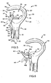
- FIG. 5 is a side elevational view of the handle assembly 320 of Figure 2.
- the handle assembly 320 includes a main member 330 and a moveable retaining member 340.
- the main member 330 partially surrounds a cord retaining space 350 sized to receive a plurality of loops (or "portions") 352 of the power cord 328 (shown in cross-sectional view in Figure 5).
- the moveable retaining member 340 may be positioned to cooperate with the main member 330 to confine at least a portion of the power cord 328 within the cord retaining space 350, such as for storing the power cord 328 when the floor care device 100 is not in use.
- the base portion 332 may be attached to the handle tube 306 in a variety of ways known to persons of ordinary skill in the art, such as by sliding the upper end of the handle tube 306 into a receiving aperture disposed in the base portion 302.
- the handle tube 306 may be secured into engagement with the base portion 332 using, for example, a set screw (not shown) or other suitable fastening device.
- the handle assembly 320 may be made by any of a variety of known means, including injection molding using a thermoplastic or thermosetting resin. If the handle assembly comprises a plurality of such injection molded components, such components may be fastened together by vibratory bonding, adhesives, screws or other fasteners, or by other means known in the art.
- the material of which the main components of the handle assembly are made is capable of withstanding impacts that may occur from an operator's dropping of the handle assembly 320.
- the upper portion 336 of the main member 330 includes a first section 337 and a second section 338.
- the first section 337 is coupled to the forward section 335 of the lower portion 334 and projects in a generally rearwardly and upwardly direction therefrom.
- the second section 337 is coupled to the first section 337 and projects in a generally rearwardly and downwardly direction therefrom.
- the upper portion 336 is sized to be comfortably and conveniently gripped by the operator, and the cord retaining space 350 is sized to comfortably receive both the plurality of power cord loops 352 and the user's fingers for ease of handling of the floor care device 100.
- the retaining member 340 of the handle assembly 320 is a generally "horn-shaped" member that somewhat resembles a cone, but having a curved central axis, an oblong cross-sectional shape, and a rounded tip.
- the retaining member 340 includes a base 342 rotatably coupled to the main member 330, and a retaining surface 344.
- the retaining member 340 is spaced apart from the upper portion 336 of the main member 330 to define a wrapping opening 354 leading to the cord retaining space 350.
- the retaining member 340 is rotatable (as indicated by arrow 345) about a retaining axis 346 between a first or “retaining" position 347, and a second or “releasing” position 349.
- the retaining position 347 the retaining surface 344 is proximate to and aligned with the concave outer surface 333 of the main member 330, and is approximately smoothly continuous therewith.
- the releasing position 347 the retaining surface 344 is rotated away from the outer surface 333 of the main member 330 such that it is remote from and not smoothly continuous with, the outer surface 333.
- the handle assembly 320 may be positioned with the retaining member 340 in the retaining position 347.
- the power cord 328 may be successively looped through the cord retaining space 350, such as by passing the plurality of loops 352 successively through the wrapping opening 354 and into the cord retaining space 350.
- the power cord 328 may also be looped about a lower cord-retaining member, such as the lower cord hook 34 of the type described above with reference to Figure 1.
- the secondary handle 328 may serve as the lower cord-retaining member.
- the retaining member 340 In the retaining position 347, the retaining member 340 is positioned such that the retaining surface 344 is adjacent the cord retaining space 350 and the retaining member 340 cooperates with the main member 330 to confine the plurality of power cord loops 352 within the cord retaining space 350.
- the power cord 328 may thereby be quickly and conveniently retained for storage or transport of the floor care device 100.
- the retaining member 340 When an operator desires to release the power cord 328, the retaining member 340 may be moved to the releasing position 349. In this position, the retaining surface 344 is moved away from the cord retaining space 350 so that the retaining member 340 does not cooperate with the main member 330 to confine the plurality of power cord loops 352 within the cord retaining space 350, and the loops 352 may be simultaneously removed from the cord retaining space 350. Also, the wrapping opening 354 is enlarged when the retaining member 340 is moved from the retaining position 347 to the releasing position 3.49. Thus, the plurality of power cord loops 352 may be quickly and conveniently removed from the cord retaining space 350.
- handle assembly 320 has been described with reference to a particular floor care device 100, namely an upright vacuum, one may note that the handle assembly 320 may be used on a wide variety of floor care devices.
- handle assemblies in accordance with the invention may be used on buffers, extractors, steam cleaners, sweepers, carpet shampooers, and other similar devices having a power cord. Therefore, handle assemblies disclosed herein should not be construed as being limited to upright vacuums.
- the retaining surface 444 cooperates with the main surface 333 of the main member 330 to retain the plurality of power cord loops 352 (not shown). Unlike the embodiment described above, however, the retaining surface 444 of the handle assembly 420 is not continuously smooth with the outer surface 333 of the main member 330. In the releasing position 449, the plurality of power cord loops 352 slip easily off of the retaining member 440.
- Figure 7 is a side elevational view of a handle assembly 520 in accordance with another embodiment of the invention.
- a main member 530 partially surrounds and defines a grip space 550, and includes a concave outer surface 533 adjacent the grip space 550.
- a retaining member 540 is pivotably attached to the main member 530 and rotates with respect to the main member 530 about a pivot axis 580.
- the retaining member 540 includes a retaining surface 544.
- the main member 530 includes a convex outer surface 534 proximate the retaining member 540.
- the retaining member 540 is pivotable between a retaining position 547 and a releasing position 549.
- the retaining surface 544 In the retaining position 547, the retaining surface 544 is spaced apart from the convex outer surface 534 of the main member 530 to create a cord retaining space 585.
- the retaining surface 544 cooperates with the convex outer surface 534 of the main member 530 to form the cord retaining space 585.
- a plurality of power cord loops 352 may then be successively wrapped over the retaining surface 544.
- the grip space 550 may also be used to retain some of the power cord loops 352.
- the retaining member 540 In the releasing position 549, the retaining member 540 is pivoted downwardly, allowing the plurality of power cord loops 352 to slip off of the retaining surface 544 and be released from the cord retaining space 585.
- Figure 8 is a side elevational view of a handle assembly 620 in accordance with yet another alternate embodiment of the invention.
- the handle assembly 620 includes a main member 630 that partially surrounds and defines a cord retaining space 650, and includes a main outer surface 633 adjacent the cord retaining space 650.
- a retaining member 640 is pivotably attached to the main member 630 and rotates with respect to the main member 630 about a pivot axis 680.
- the retaining member 640 includes a retaining surface 644 and a contoured outer surface 645.
- the retaining member 640 is pivotable between a retaining position 647, a releasing position 649, and a stowed position 651.
- the retaining position 647 the retaining surface 644 is adjacent to the cord retaining space 650 and cooperates with the main outer surface 633 of the main member 630 to retain a plurality of power cord loops 352 (not shown) within the cord retaining space 650.
- the retaining member 640 is pivoted downwardly, allowing the plurality of power cord loops 352 to slip over the retaining surface 644 and out of the cord retaining space 650.
- the retaining member 640 In the stowed position 651, the retaining member 640 is positioned with the retaining surface 644 engaged against the main member 630, and the contoured outer surface 645 of the retaining member 640 is smoothly continuous with the main outer surface 633 of the main member 630.
- the handle assembly 620 advantageously allows the retaining member 640 to be stowed so that it will not interfere with the operator's grip on the main member 630 and will not be damaged during use of the floor care device.
- FIGS 9, 9A and 9B are side elevational, front elevational and exploded isometric views of handle assembly 720 in accordance with a further alternative embodiment of the invention.
- the handle assembly 720 includes a main member 730 and a retaining member 740 that is slideably attached with the main member 730.
- the main member 730 partially surrounds and defines a cord retaining space 750.
- the retaining member 740 includes a retaining surface 744, and is slideably attached to main surface 733 by a T-member 790 formed into the retaining member 740 and is slideably moveable along the main surface 733 using slot 795 between a retaining position 747 and a releasing position 749.
- the retaining member 740 may be pivotably attached to the main member 730 by a pivot arm 782 and may pivotably move with respect to the main member 730 about a pivot line 780.
- the operator may pull downwardly on the power cord 328, drawing the power cord 328 tightly around the lower cord-retaining member (e.g. the lower cord hook 34 or a secondary handle 312) before drawing the power cord 328 upwardly to the cord retaining space 350 defined by the handle assembly 320.
- the power cord 328 is attached to the first receiving portion 360 such that the first axis 364 of the power cord 328 projects into the base portion 332 and is approximately parallel to the handle axis 307, the bending stresses that may be induced in the power cord 328 are greatly reduced compared with prior art devices.
Landscapes
- Engineering & Computer Science (AREA)
- Mechanical Engineering (AREA)
- Electric Vacuum Cleaner (AREA)
- Installation Of Indoor Wiring (AREA)
Applications Claiming Priority (2)
| Application Number | Priority Date | Filing Date | Title |
|---|---|---|---|
| US09/675,474 US6484349B1 (en) | 1999-12-30 | 2000-09-29 | Handle assemblies for floor care devices and methods of using same |
| EP01962092A EP1333745A4 (fr) | 2000-09-29 | 2001-08-10 | Ensembles a manches pour appareils d'entretien de planchers |
Related Parent Applications (1)
| Application Number | Title | Priority Date | Filing Date |
|---|---|---|---|
| EP01962092A Division EP1333745A4 (fr) | 2000-09-29 | 2001-08-10 | Ensembles a manches pour appareils d'entretien de planchers |
Publications (1)
| Publication Number | Publication Date |
|---|---|
| EP1875845A1 true EP1875845A1 (fr) | 2008-01-09 |
Family
ID=24710657
Family Applications (2)
| Application Number | Title | Priority Date | Filing Date |
|---|---|---|---|
| EP01962092A Withdrawn EP1333745A4 (fr) | 2000-09-29 | 2001-08-10 | Ensembles a manches pour appareils d'entretien de planchers |
| EP07016168A Withdrawn EP1875845A1 (fr) | 2000-09-29 | 2001-08-10 | Assemblages de poignée pour dispositifs d'entretien des sols et procédés les utilisant |
Family Applications Before (1)
| Application Number | Title | Priority Date | Filing Date |
|---|---|---|---|
| EP01962092A Withdrawn EP1333745A4 (fr) | 2000-09-29 | 2001-08-10 | Ensembles a manches pour appareils d'entretien de planchers |
Country Status (6)
| Country | Link |
|---|---|
| US (1) | US6484349B1 (fr) |
| EP (2) | EP1333745A4 (fr) |
| AU (1) | AU2001283300A1 (fr) |
| CA (1) | CA2423644C (fr) |
| MX (1) | MXPA03002685A (fr) |
| WO (1) | WO2002028254A1 (fr) |
Families Citing this family (12)
| Publication number | Priority date | Publication date | Assignee | Title |
|---|---|---|---|---|
| US6942173B1 (en) * | 2002-01-22 | 2005-09-13 | Igor Abramov | Cord storage device |
| US7765640B2 (en) * | 2003-04-09 | 2010-08-03 | Oreck Holdings, Llc | Vacuum cleaner cord management system |
| AU2005226677A1 (en) * | 2004-03-19 | 2005-10-06 | Electrolux Home Care Products, Ltd. | Circular vacuum handle |
| US20070023559A1 (en) * | 2005-07-26 | 2007-02-01 | James Scapillato | Electronic device case |
| US20070022562A1 (en) * | 2005-07-28 | 2007-02-01 | Leonard Hampton | Multi-position cleaning device handgrip |
| USD565570S1 (en) | 2006-01-31 | 2008-04-01 | Global Think Tank Llc | Top portion of a mouse |
| USD549905S1 (en) | 2006-08-18 | 2007-08-28 | Electrolux Homecare Products, Ltd. | Handle for a vacuum cleaner |
| US8082623B2 (en) * | 2008-04-23 | 2011-12-27 | Panasonic Corporation Of North America | Accessible vacuum cleaner for persons with disabilities |
| USD623501S1 (en) | 2009-06-18 | 2010-09-14 | Greg E. Blonder | Headphone holder |
| DE102010043581A1 (de) * | 2010-11-08 | 2012-05-10 | Hilti Aktiengesellschaft | Staubsauger mit einer Kabelhalteeinrichtung |
| DE202011051991U1 (de) * | 2011-11-16 | 2011-11-28 | G. Staehle Gmbh U. Co. Kg | Reinigungsgerät, insbesondere Staubsauger |
| DE102012108649A1 (de) * | 2012-09-14 | 2014-03-20 | Alfred Kärcher Gmbh & Co. Kg | Staubsauger |
Citations (7)
| Publication number | Priority date | Publication date | Assignee | Title |
|---|---|---|---|---|
| GB146117A (en) * | 1914-11-27 | 1921-01-13 | James Blaine Kirby | Improvements in and relating to handle-switches for suction-cleaners |
| US1397682A (en) * | 1916-06-17 | 1921-11-22 | P A Geier Co | Handle member |
| US1849663A (en) * | 1928-12-26 | 1932-03-15 | Walter S Finnell | Vacuum floor mopper |
| US2946071A (en) * | 1956-03-29 | 1960-07-26 | Electrolux Ab | Lifting and carrying handle for domestic appliance |
| US3193992A (en) * | 1962-12-20 | 1965-07-13 | Kingston Products Corp | Upright vacuum cleaner |
| US5887315A (en) * | 1997-03-12 | 1999-03-30 | Electrolux Llc | Handle assembly for floor supported appliances |
| DE19912235A1 (de) * | 1999-03-18 | 2000-09-21 | Bsh Bosch Siemens Hausgeraete | Anordnung eines Kabelhakens am Gehäuse eines Staubsaugers |
Family Cites Families (59)
| Publication number | Priority date | Publication date | Assignee | Title |
|---|---|---|---|---|
| US1746246A (en) * | 1928-05-21 | 1930-02-11 | Frederick W Elworthy | Vacuum cleaner attachment |
| US2037668A (en) * | 1935-08-15 | 1936-04-14 | Regina Corp | Cable releasing device |
| US3654661A (en) | 1969-11-26 | 1972-04-11 | Gen Electric | Vacuum cleaner |
| US3639941A (en) | 1970-06-16 | 1972-02-08 | Sunbeam Corp | Vacuum cleaner |
| US3971643A (en) | 1975-03-31 | 1976-07-27 | Servicemaster Industries, Inc. | Vacuum cleaner including dust bag and filter |
| DE3003309C2 (de) * | 1980-01-30 | 1982-03-04 | Siemens AG, 1000 Berlin und 8000 München | Anordnung eines Kabelhakens aus einem U-förmig gebogenen Draht an einem Staubsauger |
| US4566884A (en) | 1982-08-12 | 1986-01-28 | The Singer Company | Vacuum cleaner bag support |
| US4559665A (en) | 1984-03-02 | 1985-12-24 | Regina Corporation | Indicator nozzle for cleaning devices |
| USD287894S (en) | 1984-03-02 | 1987-01-20 | Regina Co. Inc. | Carpet cleaner |
| US4554698A (en) | 1984-07-09 | 1985-11-26 | The Hoover Company | Dispensing arrangement for an upright vacuum cleaner |
| DE3430402A1 (de) * | 1984-08-17 | 1986-02-27 | Progress-Elektrogeräte Mauz & Pfeiffer GmbH & Co, 7000 Stuttgart | Staubsaugergriff |
| US4648149A (en) | 1984-10-09 | 1987-03-10 | National Union Electric Corp. | Vacuum cleaner assembly |
| USD292335S (en) | 1985-08-08 | 1987-10-13 | The Hoover Company | Vacuum cleaner |
| USD296486S (en) | 1985-10-25 | 1988-06-28 | The Regina Co., Inc. | Vacuum cleaner |
| US5016315A (en) | 1985-11-01 | 1991-05-21 | Bissell Inc. | Floor cleaning device with improved handle grip |
| USD294988S (en) | 1985-11-01 | 1988-03-29 | Bissell Inc. | Handle grip for a vacuum cleaner |
| US4707169A (en) * | 1986-10-10 | 1987-11-17 | The Hoover Company | Cord dump and bag tensioning cap |
| USD305373S (en) | 1986-10-20 | 1990-01-02 | Sharp Corporation | Vacuum cleaner |
| US4733430A (en) | 1986-12-09 | 1988-03-29 | Whirlpool Corporation | Vacuum cleaner with operating condition indicator system |
| USD309806S (en) | 1987-05-15 | 1990-08-07 | Trc Acquisition Corporation | Vacuum cleaner |
| US4782552A (en) | 1987-07-24 | 1988-11-08 | Riccar America Company | Upright vacuum cleaner |
| US4809393A (en) * | 1987-08-20 | 1989-03-07 | Amway Corporation | Electrical appliances including a cord lock |
| USD305168S (en) | 1987-09-10 | 1989-12-19 | Riccar America Company | Upright vacuum cleaner |
| USD315623S (en) | 1990-01-11 | 1991-03-19 | Trc Acquisition Corporation | Hand held vacuum cleaner |
| US5109568A (en) * | 1990-06-15 | 1992-05-05 | Rexair, Inc. | Handle assembly for a vacuum system cleaning tool |
| JPH04152927A (ja) * | 1990-10-17 | 1992-05-26 | Matsushita Electric Ind Co Ltd | 電気掃除機等のコード保持装置 |
| JPH04189330A (ja) * | 1990-11-22 | 1992-07-07 | Matsushita Electric Ind Co Ltd | アプライト形電気掃除機 |
| DE9104750U1 (de) | 1991-04-18 | 1991-06-13 | Stein & Co GmbH, 5620 Velbert | Vorrichtung für Bürstsauger |
| USD339433S (en) | 1991-04-18 | 1993-09-14 | Stein & Co. Gmbh | Vacuum cleaner |
| US5331714A (en) * | 1991-05-20 | 1994-07-26 | The Hoover Company | Stacked looped hose rack for upright cleaner |
| USD345830S (en) | 1991-07-15 | 1994-04-05 | Trc Acquisition Corporation | Cleaning device |
| USD347504S (en) | 1991-07-15 | 1994-05-31 | The Regina Company | Hand tool for a cleaning device |
| USD346468S (en) | 1992-01-10 | 1994-04-26 | Trc Acquisition Corporation | Electric broom |
| US5230121A (en) | 1992-04-08 | 1993-07-27 | Matsushita Floor Care Company | Single motor upright vacuum cleaner |
| US5309601A (en) | 1992-10-16 | 1994-05-10 | White Consolidated Industries, Inc. | Vacuum cleaner with improved assembly |
| US5446943A (en) | 1993-01-07 | 1995-09-05 | Royal Appliance Mfg. Co. | Compact air path construction for vacuum cleaner |
| US5390392A (en) | 1993-05-17 | 1995-02-21 | White Consolidated Industries, Inc. | Vacuum cleaner bag cover with enlarged access opening |
| USD364014S (en) | 1994-01-14 | 1995-11-07 | Bissell Inc. | Wand handle for a liquid extractor vacuum cleaner |
| DE19505106C2 (de) | 1995-02-16 | 1997-04-17 | Stein & Co Gmbh | Vorrichtung für Bodenpflegegeräte |
| USD379692S (en) | 1995-03-21 | 1997-06-03 | Matsushita Electric Industrial Co., Ltd. | Electric vacuum cleaner |
| USD387517S (en) | 1995-03-21 | 1997-12-09 | Matsushita Electric Industrial Co., Ltd. | Electric vacuum cleaner |
| US5651581A (en) | 1995-09-22 | 1997-07-29 | Kolcraft Enterprises, Inc. | Infant seat handle |
| US5906024A (en) | 1996-02-08 | 1999-05-25 | Bissell Inc. | Nozzle lift and adjustment mechanism for an upright vacuum cleaner |
| ES2162185T3 (es) | 1996-03-01 | 2001-12-16 | Unilever Nv | Aparato para limpiar el suelo. |
| US5850666A (en) | 1997-01-10 | 1998-12-22 | Royal Appliance Mfg. Co. | Upright vacuum cleaner |
| USD399615S (en) | 1997-01-09 | 1998-10-13 | Oreck Holdings, Llc | Steam cleaner |
| USD398097S (en) | 1997-01-10 | 1998-09-08 | Royal Appliance Mfg. Co. | Upright vacuum cleaner |
| US6012200A (en) * | 1997-01-10 | 2000-01-11 | Royal Appliance Mfg. Co. | Upright vacuum cleaner |
| US5839160A (en) | 1997-02-21 | 1998-11-24 | Kinergy Industrial Co., Ltd. | Clutch control mechanical device for the brush axle of a vacuum cleaner |
| USD396919S (en) | 1997-05-29 | 1998-08-11 | Unique Product & Design Co., Ltd. | Combination golf buggy/bag |
| USD403480S (en) | 1997-10-15 | 1998-12-29 | Oreck Holdings, Llc | Upright vacuum cleaner |
| USD398723S (en) | 1997-10-15 | 1998-09-22 | Oreck Holdings Llc | Upright vacuum cleaner |
| USD405569S (en) | 1997-12-03 | 1999-02-09 | Matsushita Home Appliance Corporation Of America | Upright appliance handle |
| USD415324S (en) | 1998-03-19 | 1999-10-12 | Kinergy Industrial Co., Ltd. | Vacuum cleaner |
| US6079080A (en) | 1998-10-05 | 2000-06-27 | Castex Incorporated | Upright floor cleaner |
| US6243916B1 (en) * | 1999-04-06 | 2001-06-12 | Oreck Holdings, Llc | Balanced flow vacuum cleaner conduits |
| USD424261S (en) | 1999-04-06 | 2000-05-02 | Oreck Holdings, Llc | Handle for use with vacuum cleaners and other devices |
| USD426038S (en) | 1999-05-13 | 2000-05-30 | The Hoover Company | Handle portion of an upright extractor |
| US6106182A (en) * | 1999-05-27 | 2000-08-22 | Tacony Corporation | Vacuum cleaner hook assembly |
-
2000
- 2000-09-29 US US09/675,474 patent/US6484349B1/en not_active Expired - Lifetime
-
2001
- 2001-08-10 EP EP01962092A patent/EP1333745A4/fr not_active Withdrawn
- 2001-08-10 WO PCT/US2001/025198 patent/WO2002028254A1/fr not_active Ceased
- 2001-08-10 EP EP07016168A patent/EP1875845A1/fr not_active Withdrawn
- 2001-08-10 CA CA002423644A patent/CA2423644C/fr not_active Expired - Fee Related
- 2001-08-10 AU AU2001283300A patent/AU2001283300A1/en not_active Abandoned
- 2001-08-10 MX MXPA03002685A patent/MXPA03002685A/es active IP Right Grant
Patent Citations (7)
| Publication number | Priority date | Publication date | Assignee | Title |
|---|---|---|---|---|
| GB146117A (en) * | 1914-11-27 | 1921-01-13 | James Blaine Kirby | Improvements in and relating to handle-switches for suction-cleaners |
| US1397682A (en) * | 1916-06-17 | 1921-11-22 | P A Geier Co | Handle member |
| US1849663A (en) * | 1928-12-26 | 1932-03-15 | Walter S Finnell | Vacuum floor mopper |
| US2946071A (en) * | 1956-03-29 | 1960-07-26 | Electrolux Ab | Lifting and carrying handle for domestic appliance |
| US3193992A (en) * | 1962-12-20 | 1965-07-13 | Kingston Products Corp | Upright vacuum cleaner |
| US5887315A (en) * | 1997-03-12 | 1999-03-30 | Electrolux Llc | Handle assembly for floor supported appliances |
| DE19912235A1 (de) * | 1999-03-18 | 2000-09-21 | Bsh Bosch Siemens Hausgeraete | Anordnung eines Kabelhakens am Gehäuse eines Staubsaugers |
Also Published As
| Publication number | Publication date |
|---|---|
| CA2423644C (fr) | 2008-06-10 |
| US6484349B1 (en) | 2002-11-26 |
| WO2002028254A1 (fr) | 2002-04-11 |
| MXPA03002685A (es) | 2003-06-24 |
| CA2423644A1 (fr) | 2002-04-11 |
| EP1333745A1 (fr) | 2003-08-13 |
| AU2001283300A1 (en) | 2002-04-15 |
| EP1333745A4 (fr) | 2007-01-03 |
Similar Documents
| Publication | Publication Date | Title |
|---|---|---|
| US6484349B1 (en) | Handle assemblies for floor care devices and methods of using same | |
| CA2400404C (fr) | Ensemble de tuyau souple et de tube-rallonge pour aspirateur | |
| US6374453B1 (en) | Convertible vacuum cleaner | |
| US6526623B1 (en) | Handle for a vacuum cleaner | |
| EP2113183B1 (fr) | Aspirateurs verticaux | |
| US7904991B2 (en) | Suction cleaner | |
| US20120030896A1 (en) | Hand-held and conversion vacuum cleaner with adapter | |
| GB2393110A (en) | A cleaning appliance and hose storage means therefor | |
| US20090000055A1 (en) | Means for collecting garden waste | |
| EP1392147B1 (fr) | Aspirateurs comprenant un dispositif d'enroulement du cordon et des portes-accessoires pivotants integres | |
| JPH08505299A (ja) | 真空掃除機 | |
| US6446304B1 (en) | Mid-level handle for floor care device and method of using handle | |
| CN1921790A (zh) | 真空清洁器设备 | |
| CA2569034C (fr) | Ensembles a manches pour appareils d'entretien de planchers | |
| CN215305448U (zh) | 手持式吸尘设备 | |
| CN221285614U (zh) | 罐式吸尘器 | |
| JPH05199949A (ja) | 縦型電気掃除機 | |
| GB2346802A (en) | Suction cleaner handle for storing accessory tools | |
| JPH0739485A (ja) | 電気掃除機とホースユニット | |
| KR19990016097U (ko) | 세로형 진공청소기 | |
| KR19990016098U (ko) | 세로형 진공청소기 |
Legal Events
| Date | Code | Title | Description |
|---|---|---|---|
| PUAI | Public reference made under article 153(3) epc to a published international application that has entered the european phase |
Free format text: ORIGINAL CODE: 0009012 |
|
| AC | Divisional application: reference to earlier application |
Ref document number: 1333745 Country of ref document: EP Kind code of ref document: P |
|
| AK | Designated contracting states |
Kind code of ref document: A1 Designated state(s): DE GB |
|
| RIN1 | Information on inventor provided before grant (corrected) |
Inventor name: COHEN, SHANE P Inventor name: MILLARD, JEFFREY A Inventor name: LAMB, DENNIS Inventor name: ROBERTS, TERRANCE MONTY Inventor name: PATERSON, CHRIS M Inventor name: VERDURA, JAVIER |
|
| 17P | Request for examination filed |
Effective date: 20080709 |
|
| 17Q | First examination report despatched |
Effective date: 20080808 |
|
| AKX | Designation fees paid |
Designated state(s): GB |
|
| REG | Reference to a national code |
Ref country code: DE Ref legal event code: 8566 |
|
| RBV | Designated contracting states (corrected) |
Designated state(s): GB |
|
| STAA | Information on the status of an ep patent application or granted ep patent |
Free format text: STATUS: THE APPLICATION IS DEEMED TO BE WITHDRAWN |
|
| 18D | Application deemed to be withdrawn |
Effective date: 20100302 |