EP1875974A2 - Rohrbiegemaschine mit einem Positionsaufnehmer eines beweglichen Trägerelements, einem Positionsaufnehmer eines Biegeelements und einem entsprechenden Positionsanzeiger - Google Patents
Rohrbiegemaschine mit einem Positionsaufnehmer eines beweglichen Trägerelements, einem Positionsaufnehmer eines Biegeelements und einem entsprechenden Positionsanzeiger Download PDFInfo
- Publication number
- EP1875974A2 EP1875974A2 EP07252727A EP07252727A EP1875974A2 EP 1875974 A2 EP1875974 A2 EP 1875974A2 EP 07252727 A EP07252727 A EP 07252727A EP 07252727 A EP07252727 A EP 07252727A EP 1875974 A2 EP1875974 A2 EP 1875974A2
- Authority
- EP
- European Patent Office
- Prior art keywords
- pipe
- bending
- stiffback
- pin
- bending apparatus
- Prior art date
- Legal status (The legal status is an assumption and is not a legal conclusion. Google has not performed a legal analysis and makes no representation as to the accuracy of the status listed.)
- Granted
Links
Images


Classifications
-
- B—PERFORMING OPERATIONS; TRANSPORTING
- B21—MECHANICAL METAL-WORKING WITHOUT ESSENTIALLY REMOVING MATERIAL; PUNCHING METAL
- B21D—WORKING OR PROCESSING OF SHEET METAL OR METAL TUBES, RODS OR PROFILES WITHOUT ESSENTIALLY REMOVING MATERIAL; PUNCHING METAL
- B21D7/00—Bending rods, profiles, or tubes
- B21D7/16—Auxiliary equipment, e.g. for heating or cooling of bends
-
- B—PERFORMING OPERATIONS; TRANSPORTING
- B21—MECHANICAL METAL-WORKING WITHOUT ESSENTIALLY REMOVING MATERIAL; PUNCHING METAL
- B21D—WORKING OR PROCESSING OF SHEET METAL OR METAL TUBES, RODS OR PROFILES WITHOUT ESSENTIALLY REMOVING MATERIAL; PUNCHING METAL
- B21D9/00—Bending tubes using mandrels or the like
- B21D9/16—Auxiliary equipment, e.g. machines for filling tubes with sand
-
- Y—GENERAL TAGGING OF NEW TECHNOLOGICAL DEVELOPMENTS; GENERAL TAGGING OF CROSS-SECTIONAL TECHNOLOGIES SPANNING OVER SEVERAL SECTIONS OF THE IPC; TECHNICAL SUBJECTS COVERED BY FORMER USPC CROSS-REFERENCE ART COLLECTIONS [XRACs] AND DIGESTS
- Y10—TECHNICAL SUBJECTS COVERED BY FORMER USPC
- Y10S—TECHNICAL SUBJECTS COVERED BY FORMER USPC CROSS-REFERENCE ART COLLECTIONS [XRACs] AND DIGESTS
- Y10S72/00—Metal deforming
- Y10S72/702—Overbending to compensate for springback
Definitions
- the present invention relates in general to pipe bending apparatus, and more particularly to apparatus for improving the speed and accuracy of forming bends in large-diameter pipes such as the type utilized for pipelines carrying petrochemicals, and the like.
- a bend in each pipe is accomplished by making numerous small bends, each spaced from the other along the length of the pipe. For example, several half-degree, incremental bends spaced along a length of pipe may be used to create an overall curve of several degrees.
- the operator of a pipe bending machine is in full control of the number of incremental bends to be made, the spacing between the incremental bends, as well as the extent of each incremental bend in the pipe. Skilled operators can efficiently control a pipe bending machine to consistently form accurate bends in the pipes, while minimizing pipes that are damaged, under bent, or over bent. While it is possible to make consistent bends, to a certain extent, variations occur due to the skill and judgment of an operator and to differences between operators.
- the stiffback is raised to bring the pipe just to the point of contact with the bending die. This is called the 'level' or 'zero' position.
- the pin-up shoe is then brought up to support the free end of the pipe.
- the stiffback is then raised or pivoted to incrementally bend the pipe around the bending die.
- the stiffback and pin-up shoe are lowered. If further bends are required, the pipe is moved axially to a new bend position, the stiffback and pipe are brought to the level position, the pin-up shoe is raised to support the pipe, and then the stiffback is raised to bend the pipe.
- a pipe bending apparatus employing a system of sensors and indicators, and a method of operation thereof, which overcome the disadvantages and shortcomings of the prior art.
- a system of sensors and indicators is disclosed, which enables a skilled operator to quickly and consistently position and bend a pipe.
- one or more sensors are coupled to the stiffback and/or pin-up shoe.
- the position sensors are connected to a display or to indicators that provide information to the operator on the position of the pin-up shoe and stiffback. Additional sensors and indicators may provide information on the axial movement of the pipe. With the aid of feedback provided by the sensors and indicators, the skilled operator can control the pipe bending system so as to rapidly and consistently form accurate bends in pipes.
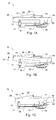
- Figs. 1A-C show a simplified representation of pipe bender 10 for forming bends in large diameter pipe, such as pipes 12 preferably having diameters between 22-36 inches, as well as other pipe diameters.
- Pipe bender 10 can accommodate pipes 12 of standard length, which in the industry is about 40 feet. Longer or shorter pipes as well as pipes having larger or smaller diameters can, of course, be operated upon by pipe bender 10.
- pipe bender 10 includes a number of components mounted on frame 11.
- the primary components of pipe bender 10 include bending die 14, stiffback 16, and pin-up shoe 18.
- Bending die 14 has a saddle-shaped bottom surface against which pipe 12 is forced during the bending operation. Bending die 14 is stationary with respect to frame 11. As can be seen in Figs. 1A-C, bending die 14 is engaged with the top surface of pipe 12. Pipe 12 is supported on its bottom surface by stiffback 16 and pin-up shoe 18.
- Stiffback 16 cradles pipe 12, and is movable or pivotable about horizontal axis 13 to raise one end of pipe 12 so as to bend the pipe around bending die 14. Hydraulic clamps hold the ends of pipe 12. Bending die 14 and stiffback 16 operate in conjunction with an internal pipe bending mandrel (not shown), which allows pipe 12 to be bent without crushing or otherwise internally deforming the circular nature of pipe 12 at the bend. Internal mandrels are well known in the art.
- Hydraulic cylinder 17 raises or lowers one end of stiffback 16. Raising stiffback 16 forces one end of pipe 12 upward.
- the opposite end of pipe 12 is supported by pin-up shoe 18, which is raised or lowered by hydraulic cylinder 19.
- Pin-up shoe 18 is raised to support pipe 12 in a fixed position while the pipe is bent, and then lowered so that the pipe can be moved axially to another location for forming another incremental bend.
- Fig. 1B illustrates stiffback 16 being pivoted in the direction of arrow 21 to form a bend in pipe 12 around the curved surface in bending die 14.
- Each pipe is generally individually bent through a specific angle at a specific location along the pipe.
- Each bend placed in pipe 12 by pipe bender 10 is limited to a certain number of degrees to avoid damage to pipe 12.
- Typical pipe benders can generally form bends of one degree or less during a single bending operation. Thus, if a greater curvature is required in a specific pipe 12 than is possible with a single bending operation, pipe 12 must undergo a number of incremental bending operations, spaced apart from each other a specified distance along the length of pipe 12.
- Winch 22 and cable 24 can be used to move pipe 12 axially by engaging the end of pipe 12 with hook 26.
- pipe 12 may be moved axially by a set of power rollers as described in detail in U.S. Pat. No. 5,092,150 , by Cunningham.
- Pin-up shoe 18 is of conventional design such that it can support pipe 12 irrespective of the orientation of the pipe. In practice, pin-up shoe 18 will initially clamp to the end of the pipe, which at that time is level or horizontal over its entire length. After the first incremental bend, both ends of pipe 12 can no longer be at a level or horizontal position. Rather, the stiffback end of pipe 12 is always maintained at a level position, while the pin-up end of pipe 12 is allowed to become elevated above the level position. This is shown in Fig. 1C. After each incremental bend, the pin-up end of pipe 12 raises higher to enable the stiffback end to maintain its level orientation. Hence, pin-up shoe 18 is structured to grasp the respective end of the pipe at whatever elevation it may assume, and to accurately and firmly maintain such elevation during the next incremental bending operation.
- stiffback 16 and pin-up shoe 18 are positioned by hydraulic cylinders.
- a control station is provided from which an operator of pipe bender 10 initiates and otherwise controls a bending operation. Controls are provided to selectively applying hydraulic pressure to the hydraulic cylinders. For example, a control may apply hydraulic pressure to hydraulic cylinder 17 to raise or lower stiffback 16. When raising pipe 12 to the level position, the operator may look for the position of pipe 12 with respect to bending die 14 and may also monitor hydraulic pressure. Similarly, another control applies hydraulic pressure to hydraulic cylinder 19 so as to raise or lower pin-up shoe 18 to pipe 12. Additional controls are used to operate other components of pipe bending machine 10, such as winch 22 and/or power rollers, if provided. The controls may be hydraulic or electrical.
- sensors and indicators are provided to directly sense, detect, and display the position of the pipe, pin-up shoe, and/or stiffback. Specific sensors and indicators may be used to implement the present invention depending on operational requirements.
- stiffback 16 and pin-up shoe 18 are positioned by hydraulic cylinders 17 and 19, respectively, under the control of an operator at control panel 25.
- Sensors 28 and 30 are coupled to stiffback 16 and pin-up shoe 18, respectively, to obtain position information.
- Display panel 29, which is coupled to the outputs of sensors 28 and 30, provides the operator a visual indication of the positions of stiffback 16 and pin-up shoe 18.
- the positions of the pin-up shoe and/or stiffback are detected by limit switches and displayed by indicator lights.
- one or more limit switches may be mounted on frame 11 in the vicinity of stiffback 16 and/or pin-up shoe 18, or their respective operating cylinders and related structures. If needed, the limit switches may be mounted on a stanchion, bracket, or other rigid support attached to pipe bending machine 10. The limit switches are located such that the limit switches open or close when the stiffback 16 or pin-up shoe 18 are in predetermined positions.
- FIG. 3 An illustrative arrangement of limit switches is shown in Fig. 3, wherein limit switches 35-37 are attached to stanchion 32 at various points along its length.
- Stanchion 32 is mounted to bending machine 10 such that the limit switches are close enough to a portion of stiffback 16 so that one or more of the limit switches are operated by stiffback 16 as it is raised or lowered.
- switch 35 when stiffback 16 is in the position shown in solid lines switch 35 has been actuated; whereas switches 36 and 37 are actuated when the stiffback is at positions 16' and 16" shown in dashed lines.
- the positions of limit switches 35-37 are mounted to stanchion 32 in such a manner that their position along the length of stanchion 32 may be adjusted as desired.
- the limit switches are connected to a display device to indicate when the stiffback and/or pin-up shoe are in predetermined positions.
- An exemplary display is shown in Fig. 4, wherein indicator lights are used to inform the operator of the position of the monitored element of machine 10.
- limit switches 35-37 directly switch the corresponding indicator lights on a display panel. For example, when stiffback 16 is at the level position, limit switch 35 may be closed causing indicator light 42 to illuminate. Additional indicator lights may indicate other positions.
- limit switch 37 may turn on indicator light 44 to indicate that stiffback 16 is at the desired height at the end of a bending operation.
- Indicator lights 46 to 49 may indicate that pin-up shoe 18 is in positions corresponding to performing a first, second, or third bend.
- the positions of limit switches 35-37 along the length of stanchion 32 are adjustable so that positions to be indicated can be established depending on the size and/or type of pipe being bent.
- the sensor and indicator system disclosed above may be used as follows.
- the operator operates the controls of machine 10 to position stiffback 16 and pin-up shoe 18 in the conventional manner, i.e., by monitoring hydraulic pressure and other visual, tactile, and audible cues.
- the position of one or more of the limit switches is adjusted so that the stiffback 16 or pin-up shoe 18 can be returned to the same position based on the indicators.
- the limit switch connected to indicator light 42 is adjusted so that when the stiffback 16 is being raised to the level position on a subsequent bend, indicator light 42 illuminates when the stiffback 16 reaches the current position, e.g., the level position.
- limit switches 35-37 may be adjusted so that limit switch 35 indicates the desired position of the pin-up shoe 18 when the pipe is unbent, limit switch 36 indicates the desired position when performing a second bend, and switch 37 indicates the desired position for performing a third bend.
- the limit switches and indicators of Fig. 3 are sufficient to indicate discrete positions of the stiffback 16 and/or pin-up shoe 18. However, adjusting the switches to accommodate different pipes requires physically moving the limit switches, which may be burdensome and time consuming.
- the limit switches are replaced by a continuous position sensor or transducer.
- position transducer 52 constitutes a cable-extension position transducer such as that identified as model P8510, obtainable from Celesco of Canoga Park, California.
- position transducer 52 constitutes a cable-extension position transducer such as that identified as model P8510, obtainable from Celesco of Canoga Park, California.
- optical, magnetic, ultrasonic, and/or electronic position sensors may be used.
- the body of the position transducer 52 is fixed to the frame or other portion of pipe bending machine 10.
- Cable 54, which extends from position transducer 52 includes end 56 adapted to be coupled to stiffback 16. Accordingly, when stiffback 16 is raised or lowered the cable is either extended from or retracted into the body of position transducer 52. The extension or retraction of cable 54 is measured by position transducer 52, and a signal indicative of the measurement is provided. Typically, the signal is an analog signal, but can also be digital in nature.
- the position of stiffback 16 is directly related to the extent of a bend formed in pipe 12. Thus, the position of stiffback 16, as measured by position transducer 52, is an indication of the pipe bend angle.
- the signal from position transducer 52 is coupled to an indicator, wherein appropriate circuitry analyzes the signal and provides a display of the position of the stiffback.
- position transducer 52 provides analog signals indicative of the positions of the stiffback 16 and pin-up shoe 18.
- position transducer 52 may comprise a potentiometer that provides an analog voltage or current signal related to the extension of cable 54.
- Appropriate comparison circuitry may be used to turn an indicator light on when the voltage of an analog signal is within a preset range.
- the circuitry may be analog circuitry such as one or more comparators that detect when the signal is within the preset range. Threshold values of the comparators may be adjustable so that bending machine 10 may be used to bend pipes having different bending characteristics.
- the circuitry may comprise an analog-to-digital converter to convert the analog signal to a digital value.
- a suitably programmed processor may then compare the digital value to previously stored threshold values.
- An output of the processor may then drive a display based on the comparison.
- the processor could simply turn on an indicator light, such as those in Fig. 4, when it determines that the converted digital value lies within a preset range of values.
- position transducer 52 may provide a digital signal related to the extension of cable 54.
- the transducer my indicate the extension of the cable by directly outputting a digital value indicative of the amount of cable extension.
- the transducer may be an encoder that outputs pulses indicative of the movement of cable 54.
- the output of the transducer may be transmitted by a wired or wireless connection to a microprocessor, which is programmed to interpret the digital signal and drive a display.
- the processor is programmed to enable easily changing various set points and indicators used by the processor software so that different pipes can be accommodated.
- a general purpose processor such as a programmable logic controller, SLC500 series, obtainable from Allen-Bradley, of Milwaukee, Wisconsin, is suitable for use in the present invention.
- the display may comprise simple indicator lights such as those shown in Fig. 4, or may comprise a video screen, such as a CRT, LCD, or other type of display.
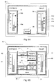
- An exemplary illustrative display is shown in Figs. 6A and 6B, wherein display panel 60 includes an LCD display with a touch screen in accordance with a preferred embodiment of the present invention.
- the signal from position sensors 28 and 30 of Fig. 2 are received by the processor and displayed on a display panel.
- the positions of stiffback 16 and pin-up 18 are indicated on virtual gauges 62 and 64 as a percent of full range.
- virtual gauges 62 and 64 show, respectively, that stiffback 16 is at approximately 38% and pin-up 18 is at approximately 59% of full range.
- various target positions are indicated by pointers 65a-b and 67a-d.
- Pointers 65a-b and 67a-d mark specific positions of these bending machine components.
- pointers 65a and 67a may correspond to the zero or level position of the stiffback 16 and pin-up shoe 18; whereas, pointer 65b indicates the maximum bend position of the 37and pointers 67b-d indicate pin-up shoe 18positions for the second, third, and fourth bend.
- the pointers are set when performing bends on a first pipe. The pointers may then be relied on while bending subsequent pipes.
- the various pointers are set by touching the corresponding button on the setup screen.
- the operator touches STIFFBACK LEVEL button 70, whereupon the processor stores an indication of the present position of the stiffback as determined by position sensor 28 of Fig. 2, and adjusts the display of pointer 65a accordingly.
- STIFFBACK BEND button 72 when stiffback 16 is raised to the maximum bend position, the operator touches STIFFBACK BEND button 72 and the processor stores the position information and updates pointer 65b.
- Pointers 67a-d are set in a similar fashion by positioning pin-up shoe 18 and touching the corresponding button.
- touching MAIN button 80 returns the display to the operational screen of Fig. 6A.
- an operator sets the setpoints by raising the stiffback 16 to the level position and pressing the STIFFBACK LEVEL button 70.
- the operator then raises the pin-up shoe 18 for engagement with the pipe 12. This constitutes the initial position of the pin-up shoe 18 for starting the first incremental bend of pipe 12.
- the position of the pin-up is entered into the processor by operating the PIN-UP LEVEL button 74.
- the maximum extent by which a pipe will be bent constitutes a "bend maximum set point", which relates to the maximum raised position of the stiffback 16 in forming a curvature in the pipe, including any spring back of the pipe 12. This may also be the maximum position that the stiffback cylinder will travel. Any attempt to bend the pipe 12 beyond the bend maximum set point may result in damage to the pipe.
- Pipe 12 is bent by raising stiffback 16 upwardly until pipe 12 "fills" the concave undersurface of bending die 14, i.e., until the pipe 12 is in contact with the die surface from the center of the bending die 14 to the frontal edge thereof, and until the pipe has been bent through the desired bend angle, taking into account any expected spring back.
- this position of the stiffback may be entered into the processor by pressing the STIFFBACK BEND 72 button on the setup screen. Pin-up shoe 18 and stiffback 16 are then lowered. The mandrel is retracted and pipe 12 is moved axially to prepare for the next incremental bend.
- pipe bending machine 10 also includes a sensor to determine the axial movement of pipe 12 such as when pipe 12 is positioned for a second or third incremental bend.
- the display panel may then indicate when pipe 12 has been moved by a specified distance.
- display panel 60 may include an indicator light that illuminates when pipe 12 has been moved axially a distance of 12 inches relative to the prior bend.
- a running indication may be kept of the total axial movement of pipe 12.
- buttons are provided for storing the position of the pin-up shoe after one, two, or three incremental bends have been performed.
- the setup procedure only has to be done the first time a given bend is performed.
- stiffback 16 and/or pin-up shoe 18 are established, e.g, by adjusting the limit switches or stroring the position signals from the position transducers, is no longer necessary to level or zero a pipe before placing a bend in the pipe. That is, after a pipe is loaded into pipe bender 10, pin-up shoe 18 is raised to a previously established pin-up shoe position. Then stiffback 16 is raised to a previously established stiffback position. This eleminates the leveling step, thereby reducing the time needed to place a bend in a pipe.
- a sensor and indicator system which provides operator feedback on the operation of a pipe bending machine and thereby enables the operator to perform highly accurate bends in the pipe in a repeatable manner.
- a touch screen for an operator interface as shown in Figs. 6A and 6B
- separate display and buttons may be used.
- those skilled in the art may prefer to embody the apparatus in other forms, and in light of the present description it will be found that such choice can be easily implemented.
Landscapes
- Engineering & Computer Science (AREA)
- Mechanical Engineering (AREA)
- Bending Of Plates, Rods, And Pipes (AREA)
- Instruments For Viewing The Inside Of Hollow Bodies (AREA)
Applications Claiming Priority (1)
| Application Number | Priority Date | Filing Date | Title |
|---|---|---|---|
| US11/428,981 US7302823B1 (en) | 2006-07-06 | 2006-07-06 | Gauge for pipe bending machine |
Publications (3)
| Publication Number | Publication Date |
|---|---|
| EP1875974A2 true EP1875974A2 (de) | 2008-01-09 |
| EP1875974A3 EP1875974A3 (de) | 2008-07-16 |
| EP1875974B1 EP1875974B1 (de) | 2010-09-08 |
Family
ID=38566860
Family Applications (1)
| Application Number | Title | Priority Date | Filing Date |
|---|---|---|---|
| EP07252727A Not-in-force EP1875974B1 (de) | 2006-07-06 | 2007-07-06 | Rohrbiegemaschine mit einem Positionsaufnehmer eines beweglichen Trägerelements, einem Positionsaufnehmer eines Biegeelements und einem entsprechenden Positionsanzeiger |
Country Status (7)
| Country | Link |
|---|---|
| US (1) | US7302823B1 (de) |
| EP (1) | EP1875974B1 (de) |
| AT (1) | ATE480343T1 (de) |
| AU (1) | AU2007203136A1 (de) |
| CA (1) | CA2593178C (de) |
| DE (1) | DE602007008981D1 (de) |
| ES (1) | ES2350294T3 (de) |
Cited By (3)
| Publication number | Priority date | Publication date | Assignee | Title |
|---|---|---|---|---|
| EP2569109A4 (de) * | 2010-05-10 | 2015-06-03 | Crc Pipeline Int Inc | Keilgetriebene rohrbiegungsmaschine |
| ITUB20152733A1 (it) * | 2015-07-31 | 2017-01-31 | Goriziane Group Spa | Macchina piegatubi per tubazioni di grande diametro |
| US9623466B2 (en) | 2012-05-30 | 2017-04-18 | Aggresive Tube Bending Inc. | Bending assembly and method therefor |
Families Citing this family (4)
| Publication number | Priority date | Publication date | Assignee | Title |
|---|---|---|---|---|
| DE102010010743B4 (de) * | 2010-03-02 | 2019-10-24 | Wafios Ag | Umformmaschine zur Herstellung von Formteilen |
| US20110259075A1 (en) * | 2010-04-27 | 2011-10-27 | Kirchmer Bryan R | Pipe Bending Machine |
| CN102274879B (zh) * | 2011-04-29 | 2013-04-17 | 张万福 | 一种不规则管材的成型机构 |
| CN120079738B (zh) * | 2025-05-06 | 2025-08-19 | 廊坊市海工机械设备有限公司 | 一种弯管机 |
Family Cites Families (21)
| Publication number | Priority date | Publication date | Assignee | Title |
|---|---|---|---|---|
| US3335588A (en) | 1964-11-06 | 1967-08-15 | Crutcher Rolfs Cummings Inc | Pipe bending machine |
| US3705506A (en) | 1971-03-31 | 1972-12-12 | Crc Crose Int Inc | Automatic positioning device |
| US3731513A (en) | 1971-07-08 | 1973-05-08 | Bell Telephone Labor Inc | Method and apparatus for bending an elongated object |
| US3766764A (en) * | 1971-10-06 | 1973-10-23 | B Ross | Automatic pipe bender |
| US3851519A (en) | 1972-06-06 | 1974-12-03 | Crc Crose Int Inc | Internal pipe supporting mandrel |
| US3834210A (en) | 1972-06-06 | 1974-09-10 | Crc Crose Int Inc | Pipe bending system |
| US4062216A (en) | 1974-07-23 | 1977-12-13 | Daiichi Koshuha Kogyo Kabushiki Kaisha | Metal bending methods and apparatus |
| US4080814A (en) | 1976-10-21 | 1978-03-28 | Eaton-Leonard Corporation | Set-up guide for bending machine |
| US4649726A (en) | 1985-09-09 | 1987-03-17 | William M. Trammell | Radio-telemetry inclinometer |
| JP2947362B2 (ja) | 1989-09-07 | 1999-09-13 | 臼井国際産業株式会社 | チューブの曲げ装置 |
| US5092150A (en) | 1991-07-19 | 1992-03-03 | Crc-Evans Pipeline International, Inc. | Pipe transport mechanism for pipe bender |
| DE4129478A1 (de) * | 1991-09-05 | 1993-03-11 | Schwarze Rigobert | Verfahren zur steuerung einer rohrbiegemaschine |
| US5275031A (en) * | 1992-06-05 | 1994-01-04 | Stark Manufacturing, Inc. | Bend correction apparatus and method |
| US5481891A (en) * | 1993-12-20 | 1996-01-09 | Eagle Precision Technologies Inc. | Tube bending apparatus and method |
| DE19522062A1 (de) * | 1995-06-17 | 1996-12-19 | Schwarze Rigobert | Verfahren zur Steuerung einer Rohrbiegemaschine |
| US5651638A (en) * | 1995-09-01 | 1997-07-29 | Crc-Evans Pipeline International, Inc. | Method and apparatus for controlling the position and operation of equipment within a pipeline |
| US5697240A (en) | 1996-10-08 | 1997-12-16 | Sabre International, Inc. | Method of determining the bend in a section of pipe |
| US6092406A (en) * | 1999-04-28 | 2000-07-25 | Crc-Evans Pipeline International, Inc. | Pipeline mandrel positioning control system |
| US6253595B1 (en) * | 1999-09-21 | 2001-07-03 | Crc-Evans Pipeline International, Inc. | Automated pipe bending machine |
| US6164113A (en) * | 2000-03-14 | 2000-12-26 | Crc-Evans Pipeline International, Inc. | Variable-speed pipe bending |
| US6980880B1 (en) * | 2003-10-14 | 2005-12-27 | Janet Ramsey | Conduit bending system |
-
2006
- 2006-07-06 US US11/428,981 patent/US7302823B1/en not_active Expired - Fee Related
-
2007
- 2007-07-05 AU AU2007203136A patent/AU2007203136A1/en not_active Abandoned
- 2007-07-06 EP EP07252727A patent/EP1875974B1/de not_active Not-in-force
- 2007-07-06 ES ES07252727T patent/ES2350294T3/es active Active
- 2007-07-06 DE DE602007008981T patent/DE602007008981D1/de active Active
- 2007-07-06 CA CA2593178A patent/CA2593178C/en not_active Expired - Fee Related
- 2007-07-06 AT AT07252727T patent/ATE480343T1/de not_active IP Right Cessation
Cited By (3)
| Publication number | Priority date | Publication date | Assignee | Title |
|---|---|---|---|---|
| EP2569109A4 (de) * | 2010-05-10 | 2015-06-03 | Crc Pipeline Int Inc | Keilgetriebene rohrbiegungsmaschine |
| US9623466B2 (en) | 2012-05-30 | 2017-04-18 | Aggresive Tube Bending Inc. | Bending assembly and method therefor |
| ITUB20152733A1 (it) * | 2015-07-31 | 2017-01-31 | Goriziane Group Spa | Macchina piegatubi per tubazioni di grande diametro |
Also Published As
| Publication number | Publication date |
|---|---|
| CA2593178A1 (en) | 2008-01-06 |
| ES2350294T8 (es) | 2011-04-13 |
| US7302823B1 (en) | 2007-12-04 |
| EP1875974B1 (de) | 2010-09-08 |
| ES2350294T3 (es) | 2011-01-20 |
| EP1875974A3 (de) | 2008-07-16 |
| ATE480343T1 (de) | 2010-09-15 |
| CA2593178C (en) | 2010-08-17 |
| AU2007203136A1 (en) | 2008-01-24 |
| DE602007008981D1 (de) | 2010-10-21 |
Similar Documents
| Publication | Publication Date | Title |
|---|---|---|
| EP1875974B1 (de) | Rohrbiegemaschine mit einem Positionsaufnehmer eines beweglichen Trägerelements, einem Positionsaufnehmer eines Biegeelements und einem entsprechenden Positionsanzeiger | |
| EP1086760B1 (de) | Automatisierte Rohrbiegevorrichtung und Verfahren zum Biegen eines Rohres | |
| US5187959A (en) | Programmable plate bending machine | |
| EP3426846B1 (de) | Rahmen mit mehreren führungsmechanismen zum führen und stützen eines gründungselements | |
| JP2013217829A (ja) | 曲げ試験装置およびこれを用いた曲げ試験方法 | |
| CN101862767A (zh) | 一种自动化钻具校直机 | |
| CN117191583B (zh) | 一种铸铁件强度检测装置 | |
| KR102275195B1 (ko) | 소리 분석 기반의 원격 밸브 제어 장치 | |
| JP6203689B2 (ja) | 自動直管化装置 | |
| CN210322629U (zh) | 一种钢筋弯曲试验机 | |
| US6516655B1 (en) | Device and method for testing sheet metal deformation | |
| JPH08174073A (ja) | 組立クランクの歪矯正装置 | |
| CN118050267B (zh) | 一种市政管道检测装置 | |
| CN114696177A (zh) | 一种导地线接续管自动压接装置 | |
| KR101018529B1 (ko) | 볼트의 연신율 측정 장치 | |
| JPH05302832A (ja) | 大型構造物のレベル出し装置 | |
| CN116116741B (zh) | 一种全自动化千斤顶静压检测装置及方法 | |
| CN207138556U (zh) | 一种精准控油的校直机 | |
| JP2017218841A (ja) | 筒体の沈設方法及び沈設支援システム | |
| CN107520287A (zh) | 一种操作便利的校直机 | |
| CN116380311B (zh) | 一种建筑钢结构应力检测装置及检测方法 | |
| CN109443624B (zh) | 一种套管钳、动力站及扭矩自动控制系统检验装置 | |
| JP3029559U (ja) | 自動ガス圧接装置に於ける接合部の縮み代計測機 | |
| CN119696269A (zh) | 一种自动潜油电机定子调直装置及方法 | |
| CN120004114A (zh) | 一种排水管道吊装安装装置 |
Legal Events
| Date | Code | Title | Description |
|---|---|---|---|
| PUAI | Public reference made under article 153(3) epc to a published international application that has entered the european phase |
Free format text: ORIGINAL CODE: 0009012 |
|
| AK | Designated contracting states |
Kind code of ref document: A2 Designated state(s): AT BE BG CH CY CZ DE DK EE ES FI FR GB GR HU IE IS IT LI LT LU LV MC MT NL PL PT RO SE SI SK TR |
|
| AX | Request for extension of the european patent |
Extension state: AL BA HR MK YU |
|
| PUAL | Search report despatched |
Free format text: ORIGINAL CODE: 0009013 |
|
| AK | Designated contracting states |
Kind code of ref document: A3 Designated state(s): AT BE BG CH CY CZ DE DK EE ES FI FR GB GR HU IE IS IT LI LT LU LV MC MT NL PL PT RO SE SI SK TR |
|
| AX | Request for extension of the european patent |
Extension state: AL BA HR MK RS |
|
| RIC1 | Information provided on ipc code assigned before grant |
Ipc: B21D 7/12 20060101ALI20080610BHEP Ipc: B21D 7/025 20060101ALI20080610BHEP Ipc: B21D 7/14 20060101AFI20071017BHEP |
|
| 17P | Request for examination filed |
Effective date: 20090114 |
|
| AKX | Designation fees paid |
Designated state(s): AT BE BG CH CY CZ DE DK EE ES FI FR GB GR HU IE IS IT LI LT LU LV MC MT NL PL PT RO SE SI SK TR |
|
| 17Q | First examination report despatched |
Effective date: 20090304 |
|
| GRAP | Despatch of communication of intention to grant a patent |
Free format text: ORIGINAL CODE: EPIDOSNIGR1 |
|
| GRAS | Grant fee paid |
Free format text: ORIGINAL CODE: EPIDOSNIGR3 |
|
| GRAA | (expected) grant |
Free format text: ORIGINAL CODE: 0009210 |
|
| AK | Designated contracting states |
Kind code of ref document: B1 Designated state(s): AT BE BG CH CY CZ DE DK EE ES FI FR GB GR HU IE IS IT LI LT LU LV MC MT NL PL PT RO SE SI SK TR |
|
| REG | Reference to a national code |
Ref country code: GB Ref legal event code: FG4D |
|
| REG | Reference to a national code |
Ref country code: CH Ref legal event code: EP |
|
| REG | Reference to a national code |
Ref country code: IE Ref legal event code: FG4D |
|
| REF | Corresponds to: |
Ref document number: 602007008981 Country of ref document: DE Date of ref document: 20101021 Kind code of ref document: P |
|
| RAP2 | Party data changed (patent owner data changed or rights of a patent transferred) |
Owner name: CRC-EVANS PIPELINE INTERNATIONAL, INC. |
|
| REG | Reference to a national code |
Ref country code: NL Ref legal event code: T3 |
|
| REG | Reference to a national code |
Ref country code: ES Ref legal event code: FG2A Effective date: 20110110 |
|
| PG25 | Lapsed in a contracting state [announced via postgrant information from national office to epo] |
Ref country code: AT Free format text: LAPSE BECAUSE OF FAILURE TO SUBMIT A TRANSLATION OF THE DESCRIPTION OR TO PAY THE FEE WITHIN THE PRESCRIBED TIME-LIMIT Effective date: 20100908 Ref country code: LT Free format text: LAPSE BECAUSE OF FAILURE TO SUBMIT A TRANSLATION OF THE DESCRIPTION OR TO PAY THE FEE WITHIN THE PRESCRIBED TIME-LIMIT Effective date: 20100908 Ref country code: FI Free format text: LAPSE BECAUSE OF FAILURE TO SUBMIT A TRANSLATION OF THE DESCRIPTION OR TO PAY THE FEE WITHIN THE PRESCRIBED TIME-LIMIT Effective date: 20100908 |
|
| LTIE | Lt: invalidation of european patent or patent extension |
Effective date: 20100908 |
|
| PG25 | Lapsed in a contracting state [announced via postgrant information from national office to epo] |
Ref country code: PL Free format text: LAPSE BECAUSE OF FAILURE TO SUBMIT A TRANSLATION OF THE DESCRIPTION OR TO PAY THE FEE WITHIN THE PRESCRIBED TIME-LIMIT Effective date: 20100908 Ref country code: SI Free format text: LAPSE BECAUSE OF FAILURE TO SUBMIT A TRANSLATION OF THE DESCRIPTION OR TO PAY THE FEE WITHIN THE PRESCRIBED TIME-LIMIT Effective date: 20100908 Ref country code: CY Free format text: LAPSE BECAUSE OF FAILURE TO SUBMIT A TRANSLATION OF THE DESCRIPTION OR TO PAY THE FEE WITHIN THE PRESCRIBED TIME-LIMIT Effective date: 20100908 |
|
| PG25 | Lapsed in a contracting state [announced via postgrant information from national office to epo] |
Ref country code: SE Free format text: LAPSE BECAUSE OF FAILURE TO SUBMIT A TRANSLATION OF THE DESCRIPTION OR TO PAY THE FEE WITHIN THE PRESCRIBED TIME-LIMIT Effective date: 20100908 Ref country code: LV Free format text: LAPSE BECAUSE OF FAILURE TO SUBMIT A TRANSLATION OF THE DESCRIPTION OR TO PAY THE FEE WITHIN THE PRESCRIBED TIME-LIMIT Effective date: 20100908 Ref country code: GR Free format text: LAPSE BECAUSE OF FAILURE TO SUBMIT A TRANSLATION OF THE DESCRIPTION OR TO PAY THE FEE WITHIN THE PRESCRIBED TIME-LIMIT Effective date: 20101209 |
|
| REG | Reference to a national code |
Ref country code: FR Ref legal event code: CA |
|
| PG25 | Lapsed in a contracting state [announced via postgrant information from national office to epo] |
Ref country code: CZ Free format text: LAPSE BECAUSE OF FAILURE TO SUBMIT A TRANSLATION OF THE DESCRIPTION OR TO PAY THE FEE WITHIN THE PRESCRIBED TIME-LIMIT Effective date: 20100908 Ref country code: IS Free format text: LAPSE BECAUSE OF FAILURE TO SUBMIT A TRANSLATION OF THE DESCRIPTION OR TO PAY THE FEE WITHIN THE PRESCRIBED TIME-LIMIT Effective date: 20110108 Ref country code: PT Free format text: LAPSE BECAUSE OF FAILURE TO SUBMIT A TRANSLATION OF THE DESCRIPTION OR TO PAY THE FEE WITHIN THE PRESCRIBED TIME-LIMIT Effective date: 20110110 Ref country code: SK Free format text: LAPSE BECAUSE OF FAILURE TO SUBMIT A TRANSLATION OF THE DESCRIPTION OR TO PAY THE FEE WITHIN THE PRESCRIBED TIME-LIMIT Effective date: 20100908 Ref country code: EE Free format text: LAPSE BECAUSE OF FAILURE TO SUBMIT A TRANSLATION OF THE DESCRIPTION OR TO PAY THE FEE WITHIN THE PRESCRIBED TIME-LIMIT Effective date: 20100908 Ref country code: RO Free format text: LAPSE BECAUSE OF FAILURE TO SUBMIT A TRANSLATION OF THE DESCRIPTION OR TO PAY THE FEE WITHIN THE PRESCRIBED TIME-LIMIT Effective date: 20100908 |
|
| PG25 | Lapsed in a contracting state [announced via postgrant information from national office to epo] |
Ref country code: BE Free format text: LAPSE BECAUSE OF FAILURE TO SUBMIT A TRANSLATION OF THE DESCRIPTION OR TO PAY THE FEE WITHIN THE PRESCRIBED TIME-LIMIT Effective date: 20100908 |
|
| PLBE | No opposition filed within time limit |
Free format text: ORIGINAL CODE: 0009261 |
|
| STAA | Information on the status of an ep patent application or granted ep patent |
Free format text: STATUS: NO OPPOSITION FILED WITHIN TIME LIMIT |
|
| 26N | No opposition filed |
Effective date: 20110609 |
|
| PG25 | Lapsed in a contracting state [announced via postgrant information from national office to epo] |
Ref country code: DK Free format text: LAPSE BECAUSE OF FAILURE TO SUBMIT A TRANSLATION OF THE DESCRIPTION OR TO PAY THE FEE WITHIN THE PRESCRIBED TIME-LIMIT Effective date: 20100908 |
|
| REG | Reference to a national code |
Ref country code: DE Ref legal event code: R097 Ref document number: 602007008981 Country of ref document: DE Effective date: 20110609 |
|
| PG25 | Lapsed in a contracting state [announced via postgrant information from national office to epo] |
Ref country code: MT Free format text: LAPSE BECAUSE OF FAILURE TO SUBMIT A TRANSLATION OF THE DESCRIPTION OR TO PAY THE FEE WITHIN THE PRESCRIBED TIME-LIMIT Effective date: 20100908 |
|
| PG25 | Lapsed in a contracting state [announced via postgrant information from national office to epo] |
Ref country code: MC Free format text: LAPSE BECAUSE OF NON-PAYMENT OF DUE FEES Effective date: 20110731 |
|
| REG | Reference to a national code |
Ref country code: CH Ref legal event code: PL |
|
| REG | Reference to a national code |
Ref country code: IE Ref legal event code: MM4A |
|
| PG25 | Lapsed in a contracting state [announced via postgrant information from national office to epo] |
Ref country code: CH Free format text: LAPSE BECAUSE OF NON-PAYMENT OF DUE FEES Effective date: 20110731 Ref country code: LI Free format text: LAPSE BECAUSE OF NON-PAYMENT OF DUE FEES Effective date: 20110731 |
|
| PG25 | Lapsed in a contracting state [announced via postgrant information from national office to epo] |
Ref country code: IE Free format text: LAPSE BECAUSE OF NON-PAYMENT OF DUE FEES Effective date: 20110706 |
|
| PG25 | Lapsed in a contracting state [announced via postgrant information from national office to epo] |
Ref country code: LU Free format text: LAPSE BECAUSE OF NON-PAYMENT OF DUE FEES Effective date: 20110706 |
|
| PG25 | Lapsed in a contracting state [announced via postgrant information from national office to epo] |
Ref country code: TR Free format text: LAPSE BECAUSE OF FAILURE TO SUBMIT A TRANSLATION OF THE DESCRIPTION OR TO PAY THE FEE WITHIN THE PRESCRIBED TIME-LIMIT Effective date: 20100908 Ref country code: BG Free format text: LAPSE BECAUSE OF FAILURE TO SUBMIT A TRANSLATION OF THE DESCRIPTION OR TO PAY THE FEE WITHIN THE PRESCRIBED TIME-LIMIT Effective date: 20101208 |
|
| PG25 | Lapsed in a contracting state [announced via postgrant information from national office to epo] |
Ref country code: HU Free format text: LAPSE BECAUSE OF FAILURE TO SUBMIT A TRANSLATION OF THE DESCRIPTION OR TO PAY THE FEE WITHIN THE PRESCRIBED TIME-LIMIT Effective date: 20100908 |
|
| PGFP | Annual fee paid to national office [announced via postgrant information from national office to epo] |
Ref country code: ES Payment date: 20130726 Year of fee payment: 7 Ref country code: DE Payment date: 20130729 Year of fee payment: 7 Ref country code: NL Payment date: 20130726 Year of fee payment: 7 |
|
| PGFP | Annual fee paid to national office [announced via postgrant information from national office to epo] |
Ref country code: GB Payment date: 20130729 Year of fee payment: 7 Ref country code: FR Payment date: 20130717 Year of fee payment: 7 |
|
| PGFP | Annual fee paid to national office [announced via postgrant information from national office to epo] |
Ref country code: IT Payment date: 20130722 Year of fee payment: 7 |
|
| REG | Reference to a national code |
Ref country code: DE Ref legal event code: R119 Ref document number: 602007008981 Country of ref document: DE |
|
| REG | Reference to a national code |
Ref country code: NL Ref legal event code: V1 Effective date: 20150201 |
|
| GBPC | Gb: european patent ceased through non-payment of renewal fee |
Effective date: 20140706 |
|
| PG25 | Lapsed in a contracting state [announced via postgrant information from national office to epo] |
Ref country code: NL Free format text: LAPSE BECAUSE OF NON-PAYMENT OF DUE FEES Effective date: 20150201 |
|
| REG | Reference to a national code |
Ref country code: FR Ref legal event code: ST Effective date: 20150331 |
|
| PG25 | Lapsed in a contracting state [announced via postgrant information from national office to epo] |
Ref country code: IT Free format text: LAPSE BECAUSE OF NON-PAYMENT OF DUE FEES Effective date: 20140706 Ref country code: DE Free format text: LAPSE BECAUSE OF NON-PAYMENT OF DUE FEES Effective date: 20150203 |
|
| REG | Reference to a national code |
Ref country code: DE Ref legal event code: R119 Ref document number: 602007008981 Country of ref document: DE Effective date: 20150203 |
|
| PG25 | Lapsed in a contracting state [announced via postgrant information from national office to epo] |
Ref country code: FR Free format text: LAPSE BECAUSE OF NON-PAYMENT OF DUE FEES Effective date: 20140731 Ref country code: GB Free format text: LAPSE BECAUSE OF NON-PAYMENT OF DUE FEES Effective date: 20140706 |
|
| REG | Reference to a national code |
Ref country code: ES Ref legal event code: FD2A Effective date: 20160129 |
|
| PG25 | Lapsed in a contracting state [announced via postgrant information from national office to epo] |
Ref country code: ES Free format text: LAPSE BECAUSE OF NON-PAYMENT OF DUE FEES Effective date: 20140707 |