EP1876041A2 - Suspension de roue pour véhicules automobiles - Google Patents
Suspension de roue pour véhicules automobiles Download PDFInfo
- Publication number
- EP1876041A2 EP1876041A2 EP07007892A EP07007892A EP1876041A2 EP 1876041 A2 EP1876041 A2 EP 1876041A2 EP 07007892 A EP07007892 A EP 07007892A EP 07007892 A EP07007892 A EP 07007892A EP 1876041 A2 EP1876041 A2 EP 1876041A2
- Authority
- EP
- European Patent Office
- Prior art keywords
- wheel
- bearing
- link
- arm
- support arm
- Prior art date
- Legal status (The legal status is an assumption and is not a legal conclusion. Google has not performed a legal analysis and makes no representation as to the accuracy of the status listed.)
- Withdrawn
Links
Images


Classifications
-
- B—PERFORMING OPERATIONS; TRANSPORTING
- B60—VEHICLES IN GENERAL
- B60G—VEHICLE SUSPENSION ARRANGEMENTS
- B60G7/00—Pivoted suspension arms; Accessories thereof
- B60G7/02—Attaching arms to sprung part of vehicle
-
- B—PERFORMING OPERATIONS; TRANSPORTING
- B60—VEHICLES IN GENERAL
- B60G—VEHICLE SUSPENSION ARRANGEMENTS
- B60G7/00—Pivoted suspension arms; Accessories thereof
- B60G7/006—Attaching arms to sprung or unsprung part of vehicle, characterised by comprising attachment means controlled by an external actuator, e.g. a fluid or electrical motor
-
- F—MECHANICAL ENGINEERING; LIGHTING; HEATING; WEAPONS; BLASTING
- F16—ENGINEERING ELEMENTS AND UNITS; GENERAL MEASURES FOR PRODUCING AND MAINTAINING EFFECTIVE FUNCTIONING OF MACHINES OR INSTALLATIONS; THERMAL INSULATION IN GENERAL
- F16F—SPRINGS; SHOCK-ABSORBERS; MEANS FOR DAMPING VIBRATION
- F16F1/00—Springs
- F16F1/36—Springs made of rubber or other material having high internal friction, e.g. thermoplastic elastomers
- F16F1/38—Springs made of rubber or other material having high internal friction, e.g. thermoplastic elastomers with a sleeve of elastic material between a rigid outer sleeve and a rigid inner sleeve or pin, i.e. bushing-type
- F16F1/387—Springs made of rubber or other material having high internal friction, e.g. thermoplastic elastomers with a sleeve of elastic material between a rigid outer sleeve and a rigid inner sleeve or pin, i.e. bushing-type comprising means for modifying the rigidity in particular directions
-
- B—PERFORMING OPERATIONS; TRANSPORTING
- B60—VEHICLES IN GENERAL
- B60G—VEHICLE SUSPENSION ARRANGEMENTS
- B60G2200/00—Indexing codes relating to suspension types
- B60G2200/10—Independent suspensions
- B60G2200/18—Multilink suspensions, e.g. elastokinematic arrangements
- B60G2200/184—Assymetric arrangements
-
- B—PERFORMING OPERATIONS; TRANSPORTING
- B60—VEHICLES IN GENERAL
- B60G—VEHICLE SUSPENSION ARRANGEMENTS
- B60G2200/00—Indexing codes relating to suspension types
- B60G2200/40—Indexing codes relating to the wheels in the suspensions
- B60G2200/44—Indexing codes relating to the wheels in the suspensions steerable
-
- B—PERFORMING OPERATIONS; TRANSPORTING
- B60—VEHICLES IN GENERAL
- B60G—VEHICLE SUSPENSION ARRANGEMENTS
- B60G2200/00—Indexing codes relating to suspension types
- B60G2200/40—Indexing codes relating to the wheels in the suspensions
- B60G2200/462—Toe-in/out
-
- B—PERFORMING OPERATIONS; TRANSPORTING
- B60—VEHICLES IN GENERAL
- B60G—VEHICLE SUSPENSION ARRANGEMENTS
- B60G2204/00—Indexing codes related to suspensions per se or to auxiliary parts
- B60G2204/10—Mounting of suspension elements
- B60G2204/14—Mounting of suspension arms
- B60G2204/143—Mounting of suspension arms on the vehicle body or chassis
-
- B—PERFORMING OPERATIONS; TRANSPORTING
- B60—VEHICLES IN GENERAL
- B60G—VEHICLE SUSPENSION ARRANGEMENTS
- B60G2204/00—Indexing codes related to suspensions per se or to auxiliary parts
- B60G2204/40—Auxiliary suspension parts; Adjustment of suspensions
- B60G2204/41—Elastic mounts, e.g. bushings
- B60G2204/4104—Bushings having modified rigidity in particular directions
- B60G2204/41042—Bushings having modified rigidity in particular directions by using internal cam surfaces
Definitions
- the invention relates to a suspension for motor vehicles according to the preamble of claim 1.
- Generic suspension describes the JP 04345510 A in which a body-side arm bearing is proposed for both steerable wheels and unguided wheels of motor vehicles, which has asymmetrically arranged means which produce a targeted steering effect, in particular during braking of the motor vehicle due to the longitudinal forces occurring associated with the elastokinematic displacement of the handlebar the wheel is adjusted in the direction of toe.
- the means for adjusting or displacement of the relevant arm of the suspension can, for. B. a harder in its spring rate annular body in the rubber-elastic bearing body (Fig. 6, 13) or designed with a different outer diameter inner sleeve (Fig. 10, 11) of the link bearing.
- the measures mentioned inevitably lead to a deterioration of the ride comfort of the motor vehicle degradation of the damping characteristics of the respective link bearing.
- Another suspension which comprises a dissolved lower handlebar assembly with a steering rod tie rod, a wishbone and a strut.
- the wishbone is facing the vehicle transverse axis at an angle of 4 ° to 20 ° forward swept.
- One of the tie rod and the wishbone formed instantaneous pole is located over a distance up to 3000mm from the wheel center.
- the object of the invention is to propose a generic suspension, which is designed structurally simple and with good damping properties at even more favorable influencing the elastokinematic properties.
- the means are designed so that an adjustment and associated hardening of the bearing detection of the link bearing takes place only in one effective direction. It was recognized that a particular occurring during a braking operation or lateral forces (curves) hardening of the link bearing does not comfort-reducing effect, while in the rest of driving the link bearing can have good damping properties.
- a suspension with at least at the lower arm level arranged links which in a dissolved formation approximately transverse to the vertical vehicle longitudinal center and the wheel center arranged support arm, a lying behind it, obliquely forwardly extending outside guide arm and a front lying about aligned parallel to the support arm, third link (steered wheels of a tie rod) and are articulated on the one hand via steering bearings on the body of the motor vehicle and on the other hand ball joints on the wheel
- the body-side arm bearing of the support arm is provided with means that the Support arm caused by displacements caused by braking torques and / or compression movements of the wheel inside, to adjust the vertical vehicle center.
- the background is that in such a suspension at a favorable for the ride comfort interpretation of the arm bearings (relatively soft) avoided unwanted self-steering movements and possibly a targeted on track of the wheel is set (advantageous understeer when braking and in bends).
- the body-side arm bearing of the support arm can be provided with means that the support arm caused by braking torques and / or compression movements of the wheel displacements in the direction of travel F forward, the body-side arm bearing of the third link (tie rod 16 ) to adjust.
- the instantaneous pole defined by the third link and the support arm by their imaginary extensions is changed and shifted so that an advantageous understeer when driving through curves also occurs.
- the instantaneous pole in the design position with the vehicle stationary or in the state of stationary straight-ahead driving can be at a distance of 3000 mm or more from the center of the wheel. Only with a corresponding application of force, the instantaneous pole distance can be reduced in terms of driving dynamics to less than 3000 mm.
- the stability during straight travel can be further increased if the support angle with an angle of less than 4 ° relative to the vehicle transverse axis is swept forward.
- the driving behavior is also favored if the instantaneous center, regardless of the effect of lateral and / or lateral forces on the wheel is always in front of the wheel center.
- a handlebar-side outer sleeve and an annular rubber-elastic bearing body is proposed structurally and manufacturing technology particularly simple manner that at least one pressure-rigid actuator between the inner sleeve and the outer sleeve is provided outside the extended handlebar longitudinal center axis, only causes a bearing stiffening or handlebar adjustment in the intended direction of action.
- the actuator can be made of metal or a particularly hard, wear-resistant plastic.
- the pressure-resistant actuating element may in particular be at least one rolling element embedded in the rubber-elastic bearing body, which thus acts almost wear-free and friction-free, in particular in the case of spring-loaded movements with corresponding torsional stress on the arm bearing of the wheel suspension.
- the at least one rolling element may have spherical contact surfaces with the inner sleeve and outer sleeve of the arm bearing, that is to say in the form of a ball or barrel-shaped roller, etc.
- the pressure-resistant adjusting element can advantageously be guided on the inner sleeve and / or the outer sleeve of the link bearing in an inclined oblique plane to a plane of rotation for displacing the link in the axial direction.
- the link bearing can be formed by at least two adjacently arranged link bearings, of which one link bearing is provided with the means for displacing the link.
- the inner sleeve or the outer sleeve of the arm bearing can be asymmetrical, wherein these are to be formed so that in turn an adjustment and associated hardening of the position detection of the arm bearing takes place only in one effective direction.
- the asymmetrically formed inner sleeve and / or outer sleeve can be combined with at least one pressure-resistant control element. This makes it possible, not only during the braking process of the motor vehicle (tilting movement of the handlebar), but also in fürfederzien (pivotal movement of the handlebar) to impose a targeted displacement of the handlebar and associated self-steering movements in the elastokinematic region of the suspension.
- a suspension 10 for the steered wheels of a motor vehicle is shown diagrammatically, with an approximately transversely to the vertical center axis and centered in the wheel center support arm 12, seen in the direction of travel of the motor vehicle behind it, obliquely forward and outside extending guide arm 14 and a front, approximately parallel to the support arm 12 extending tie rod 16 of a rack-and-pinion steering not shown 18.
- the tie rod 16 may be formed by a third link.
- the imaginary extensions (dot-dashed lines) of the tie rod 16 and the support arm 12 form a Momentanpol Mp, which is as shown in FIGS . 1 and 2 by a defined degree within the left wheel 34 of the illustrated suspension 10 and in front of the wheel center.
- the links 12, 14 are arranged in a resolved formation, with link bearings 20, 22 which are articulated to the body of the motor vehicle, not shown, and with link bearings or ball joints 24, 26, which on an only indicated wheel carrier 32 are hinged, which receives in the embodiment left front wheel 34 of the motor vehicle in a known manner.
- link bearings 20, 22 which are articulated to the body of the motor vehicle, not shown
- link bearings or ball joints 24, 26, which on an only indicated wheel carrier 32 are hinged, which receives in the embodiment left front wheel 34 of the motor vehicle in a known manner.
- the tie rod 16 via ball joints 28, 30 is pivotally connected to a steering arm of the wheel carrier 32 and the rack of the rack and pinion steering 18.
- the suspension may have a split link formation or a single link.
- the suspension spring or a strut with shock absorbers of the suspension are not shown;
- a strut may be supported on the support arm 12.
- the ball joints 24, 26, 28, 30 may be known type.
- the body-side arm bearing 20, 22 are - unless otherwise described below - conventional rubber-metal sleeve bearing (eg., As shown in FIG. 5 ).
- Fig. 1 the stress of the links 12, 14 and the tie rod 16 is shown at a lateral force S on the wheel 34 and the wheel carrier 32 by arrows.
- An increased lateral force S occurs, for example, when driving through curves on the respective outer wheel 34. In the illustration, however, the respective steering angle is disregarded for comparison purposes.
- Fig. 2 the stress of the handlebars 12, 14 and the tie rod 16 of the suspension is explained when braking the motor vehicle.
- the corresponding disc brake on the wheel carrier 32 and wheel 34 is not shown and conventional design and arrangement.
- the arm bearing 20 of the support arm 12 In order to counteract the tendency of the elastokinematic adjustment of the wheel 34 during braking and additionally with lateral forces S or preferably to impose an adjustment of the wheel 34 on the rearward trace ⁇ (according to FIG. 1 ), the arm bearing 20 of the support arm 12 according to FIGS . 3, 4, 6 or 7 executed.
- the arm bearing 20 (and also 22) is initially in a conventional manner from an attached by means of a screw, not shown on a body-side bracket inner sleeve 36, attached to the support arm 12 outer sleeve 38 and disposed therebetween, rubber-elastic and annular bearing body 40 together.
- the bearing body 40 for example, from a suitable elastomer is firmly connected to the inner sleeve 36 and the outer sleeve 38 by vulcanization and has in the usual way a defined spring damping rate, the good ride comfort of the motor vehicle ensures.
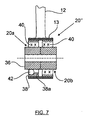
- the outer sleeve 38 can also be pressed into a bearing eye 13 (FIG. 7) of the support arm 12.
- armature bearing 20 and in the bearing body 40 is as a means for selective hardening of the support arm 12 against the said pulling direction during braking a pressure-resistant or metallic ball 42 integrated, which starts at the inner sleeve 36 and the outer sleeve 38 at unloaded arm bearing 20 and which is positioned diametrically opposite the connection of the support arm 12 to the outer sleeve 38.
- the ball 42 may in particular be positively embedded in the bearing body 40 and therefore held captive.
- the ball 42 is ineffective and possibly lifts off from the inner sleeve 36 and / or the outer sleeve 38.
- the spring and damping properties of the link bearing 20 thus remain substantially unchanged.
- the ball 42 applies to the inner sleeve 36 and the outer sleeve 38 and now causes a hardening of the arm bearing 20 in the pulling direction.
- the means for hardening and displacement of the arm bearing 20 and the ball 42 is further arranged outside the extended longitudinal axis 12a of the support arm 12 (see Figures 4 and 6) such that the ball 42 forms a lever arm a to the longitudinal central axis 12a.
- This lever arm a additionally causes a displacement of the support arm 12 against the tensile stress during braking, because due to the longitudinal forces L of the support arm 12 against the direction of travel F is pivoted to the rear about the vertical axis of the arm bearing 20 (shown exaggerated in Fig. 6 ).
- the support arm 12 is thus on the pressure-resistant means or the ball 42 to the travel s compared to a conventional arm bearing 20 '(see Fig. 5) adjusted inwards. This causes on the wheel 34 of the suspension 10 to go on track (toe angle ⁇ ), as shown in FIG .
- the inner sleeve 36 of the arm bearing 20 is not rotationally symmetrical, but asymmetrically designed so that it causes about the ball 42 an additional displacement of the support arm 12 to the inside of the vehicle center.
- the inner sleeve 36 (and possibly the outer sleeve 38) may be cam-shaped or eccentric (as shown) and starting from a construction position (average height of the motor vehicle) of the suspension 10 at an increasing torsional load of the arm bearing 20 (during compression of the wheel 34th ) control a further, targeted displacement of the support arm 12 with a correspondingly enlarged displacement s (in comparison to FIG. 5) .
- the asymmetrical design of the inner sleeve 36 may be provided continuously or only in the area of the ball 42.
- FIG 7 shows another embodiment of the body-side arm bearing 20 "of the support arm 12, which is composed of two separate arm bearings 20a and 20b.
- the arm bearing 20b is carried out conventionally, so according to the above-described Fig. 5 with an inner sleeve 36, an outer sleeve 38 and a rubber-elastic bearing body 40 executed.
- the axially adjacent arm bearing 20a in turn has the rolling element or the metallic ball 42, which starts at the inner sleeve 36 and the outer sleeve 38 with unloaded arm bearing 20a and which is positioned diametrically opposite the connection of the support arm 12 to the outer sleeve 38.
- the ball 42 additionally runs on a machined into the outer sleeve 38 Slideway 38a, which extends obliquely to an imaginary plane of rotation, in such a way that they at a compression of the wheel 34 and a corresponding pivoting of the support arm 12, the body-side bearing point of the support arm 12 and the arm bearing 20 "forward, the arm bearing 28 of the tie rod 16 to move.
- the invention is not limited to the illustrated embodiment.
- a suspension 10 with dissolved link formation another suspension may be used, in which a reversal of the tensile and compressive forces may occur at least one link or link bearing during braking and / or lateral forces.
- the suspension 10 can be designed as both a steered front suspension or as unguided rear suspension.
- one or more balls 42 may be used as pressure-resistant means and one or more rollers or sliders, possibly also made of a harder, wear-resistant plastic.
- the pressure-resistant means may possibly be formed directly on the inner sleeve 36 or on the outer sleeve 38.
Landscapes
- Engineering & Computer Science (AREA)
- Mechanical Engineering (AREA)
- General Engineering & Computer Science (AREA)
- Vehicle Body Suspensions (AREA)
Applications Claiming Priority (1)
| Application Number | Priority Date | Filing Date | Title |
|---|---|---|---|
| DE102006031001A DE102006031001B4 (de) | 2006-07-05 | 2006-07-05 | Radaufhängung für Kraftfahrzeuge |
Publications (2)
| Publication Number | Publication Date |
|---|---|
| EP1876041A2 true EP1876041A2 (fr) | 2008-01-09 |
| EP1876041A3 EP1876041A3 (fr) | 2014-07-23 |
Family
ID=38510378
Family Applications (1)
| Application Number | Title | Priority Date | Filing Date |
|---|---|---|---|
| EP07007892.8A Withdrawn EP1876041A3 (fr) | 2006-07-05 | 2007-04-18 | Suspension de roue pour véhicules automobiles |
Country Status (2)
| Country | Link |
|---|---|
| EP (1) | EP1876041A3 (fr) |
| DE (1) | DE102006031001B4 (fr) |
Families Citing this family (1)
| Publication number | Priority date | Publication date | Assignee | Title |
|---|---|---|---|---|
| DE102011013484B4 (de) | 2011-03-10 | 2013-08-29 | Audi Ag | Radaufhängung für die Hinterräder eines Kraftfahrzeuges |
Citations (2)
| Publication number | Priority date | Publication date | Assignee | Title |
|---|---|---|---|---|
| JPH04345510A (ja) | 1991-05-22 | 1992-12-01 | Nissan Motor Co Ltd | サスペンション |
| EP1637366A1 (fr) | 2004-09-11 | 2006-03-22 | Bayerische Motoren Werke Aktiengesellschaft | Essieu avant de vehicule à double voie avec de bras inférieure séparé |
Family Cites Families (9)
| Publication number | Priority date | Publication date | Assignee | Title |
|---|---|---|---|---|
| JPS58126206A (ja) * | 1982-01-20 | 1983-07-27 | Nissan Motor Co Ltd | 後輪独立懸架装置 |
| JPS61160308A (ja) * | 1985-01-08 | 1986-07-21 | Toyota Motor Corp | 後輪懸架装置 |
| JPH0694245B2 (ja) * | 1986-04-25 | 1994-11-24 | マツダ株式会社 | 自動車のサスペンシヨン |
| JPH0624881B2 (ja) * | 1985-04-30 | 1994-04-06 | 富士重工業株式会社 | パラレルリンク式後輪懸架装置 |
| US5507510A (en) * | 1993-03-26 | 1996-04-16 | Honda Giken Kogyo Kabushiki Kaisha | Multi-link type suspension system |
| JP3796767B2 (ja) * | 1995-05-26 | 2006-07-12 | 日産自動車株式会社 | ブッシュ及び車両用サスペンションの取付構造 |
| DE10304567A1 (de) * | 2003-02-05 | 2004-08-19 | Audi Ag | Radaufhängung für Kraftfahrzeuge |
| JP4400310B2 (ja) * | 2004-05-31 | 2010-01-20 | トヨタ自動車株式会社 | 操舵輪用ダブルジョイント式サスペンション |
| DE102005031154A1 (de) * | 2005-07-04 | 2007-01-18 | Audi Ag | Radaufhängung für die gelenkten Räder eines Kraftfahrzeuges |
-
2006
- 2006-07-05 DE DE102006031001A patent/DE102006031001B4/de not_active Expired - Fee Related
-
2007
- 2007-04-18 EP EP07007892.8A patent/EP1876041A3/fr not_active Withdrawn
Patent Citations (2)
| Publication number | Priority date | Publication date | Assignee | Title |
|---|---|---|---|---|
| JPH04345510A (ja) | 1991-05-22 | 1992-12-01 | Nissan Motor Co Ltd | サスペンション |
| EP1637366A1 (fr) | 2004-09-11 | 2006-03-22 | Bayerische Motoren Werke Aktiengesellschaft | Essieu avant de vehicule à double voie avec de bras inférieure séparé |
Also Published As
| Publication number | Publication date |
|---|---|
| EP1876041A3 (fr) | 2014-07-23 |
| DE102006031001B4 (de) | 2013-11-28 |
| DE102006031001A1 (de) | 2008-03-27 |
Similar Documents
| Publication | Publication Date | Title |
|---|---|---|
| DE19811903B4 (de) | Radaufhängung | |
| DE4108164C2 (fr) | ||
| EP3221162B1 (fr) | Essieu de roues d'un véhicule automobile à deux voies et véhicule automobile à deux voies muni dudit essieu | |
| DE102013210338A1 (de) | Mehrlenkerhinterachse für ein Fahrzeug | |
| EP2497660B1 (fr) | Axe de véhicule automobile doté d'un axe de direction virtuel | |
| DE4341559C2 (de) | Anti-Roll-System für Fahrzeuge | |
| DE102007051470A1 (de) | Verbundlenkerachse eines zweispurigen Fahrzeugs | |
| DE102011082768A1 (de) | Lenkbare Verbundlenkerachse | |
| DE102016217475B4 (de) | Crashanordnung | |
| WO2017191023A1 (fr) | Suspension à roues indépendantes d'un véhicule, dotée d'un élément formant ressort à lame guidant les roues, réalisé dans un matériau composite fibreux | |
| DE2645272B2 (de) | Radaufhängung für Kraftfahrzeuge | |
| DE102009040163B4 (de) | Achsführungslager zur Ankopplung einer Hinterachse an einen Fahrzeugaufbau | |
| DE102006015671A1 (de) | Fahrzeug-Achskörper | |
| DE102013216029A1 (de) | Lenkbare Vorderachse für Räder eines zweispurigen Kraftfahrzeugs und zweispuriges Kraftfahrzeug mit einer solchen Vorderachse | |
| DE102011005611A1 (de) | Vorrichtung und Verfahren zur Lenkung der Räder einer mittels Achsschenkellenkung lenkbaren Fahrzeugachse | |
| EP1565370B1 (fr) | Palier pivotant et essieu orientable muni d'un tel palier | |
| EP1995087B1 (fr) | Suspension de roue pour véhicules automobiles | |
| DE102016207631A1 (de) | Einzelradaufhängung eines Fahrzeugs mit einem radführenden Blattfederelement aus einem Faserverbund-Werkstoff | |
| DE3912520B4 (de) | Hinterachse für ein Kraftfahrzeug | |
| DE102013218701B3 (de) | Verbundlenkerachse für ein Fahrzeug sowie Lageranordnung für eine Verbundlenkerachse | |
| DE10351574B4 (de) | Verfahren zur Veränderung des Eigenlenkverhaltens der Hinterräder eines zweispurigen Kraftfahrzeugs | |
| DE102015116799A1 (de) | Fahrwerkslager | |
| DE102015009311A1 (de) | Radaufhängung für eine Fahrzeugachse | |
| DE102005011253A1 (de) | Vorrichtung zum längenveränderlichen Verstellen eines Lenkers | |
| DE102006031001B4 (de) | Radaufhängung für Kraftfahrzeuge |
Legal Events
| Date | Code | Title | Description |
|---|---|---|---|
| PUAI | Public reference made under article 153(3) epc to a published international application that has entered the european phase |
Free format text: ORIGINAL CODE: 0009012 |
|
| AK | Designated contracting states |
Kind code of ref document: A2 Designated state(s): AT BE BG CH CY CZ DE DK EE ES FI FR GB GR HU IE IS IT LI LT LU LV MC MT NL PL PT RO SE SI SK TR |
|
| AX | Request for extension of the european patent |
Extension state: AL BA HR MK YU |
|
| PUAL | Search report despatched |
Free format text: ORIGINAL CODE: 0009013 |
|
| AK | Designated contracting states |
Kind code of ref document: A3 Designated state(s): AT BE BG CH CY CZ DE DK EE ES FI FR GB GR HU IE IS IT LI LT LU LV MC MT NL PL PT RO SE SI SK TR |
|
| AX | Request for extension of the european patent |
Extension state: AL BA HR MK RS |
|
| RIC1 | Information provided on ipc code assigned before grant |
Ipc: B60G 7/02 20060101AFI20140619BHEP Ipc: F16F 1/387 20060101ALI20140619BHEP Ipc: B62D 17/00 20060101ALI20140619BHEP |
|
| 17P | Request for examination filed |
Effective date: 20150123 |
|
| RBV | Designated contracting states (corrected) |
Designated state(s): AT BE BG CH CY CZ DE DK EE ES FI FR GB GR HU IE IS IT LI LT LU LV MC MT NL PL PT RO SE SI SK TR |
|
| AKX | Designation fees paid |
Designated state(s): DE FR GB IT |
|
| AXX | Extension fees paid |
Extension state: HR Extension state: BA Extension state: MK Extension state: AL Extension state: RS |
|
| GRAP | Despatch of communication of intention to grant a patent |
Free format text: ORIGINAL CODE: EPIDOSNIGR1 |
|
| INTG | Intention to grant announced |
Effective date: 20160330 |
|
| STAA | Information on the status of an ep patent application or granted ep patent |
Free format text: STATUS: THE APPLICATION IS DEEMED TO BE WITHDRAWN |
|
| 18D | Application deemed to be withdrawn |
Effective date: 20160810 |