EP1876059A1 - Dispositif de retenue pour un vélo - Google Patents
Dispositif de retenue pour un vélo Download PDFInfo
- Publication number
- EP1876059A1 EP1876059A1 EP07012922A EP07012922A EP1876059A1 EP 1876059 A1 EP1876059 A1 EP 1876059A1 EP 07012922 A EP07012922 A EP 07012922A EP 07012922 A EP07012922 A EP 07012922A EP 1876059 A1 EP1876059 A1 EP 1876059A1
- Authority
- EP
- European Patent Office
- Prior art keywords
- holding device
- receiving element
- crank arm
- actuator
- adjusting
- Prior art date
- Legal status (The legal status is an assumption and is not a legal conclusion. Google has not performed a legal analysis and makes no representation as to the accuracy of the status listed.)
- Ceased
Links
- 239000013013 elastic material Substances 0.000 claims description 4
- 239000012858 resilient material Substances 0.000 claims description 3
- 238000010276 construction Methods 0.000 description 2
- 108010000020 Platelet Factor 3 Proteins 0.000 description 1
- 230000006835 compression Effects 0.000 description 1
- 238000007906 compression Methods 0.000 description 1
- 239000000463 material Substances 0.000 description 1
- 210000002105 tongue Anatomy 0.000 description 1
Images



Classifications
-
- B—PERFORMING OPERATIONS; TRANSPORTING
- B60—VEHICLES IN GENERAL
- B60R—VEHICLES, VEHICLE FITTINGS, OR VEHICLE PARTS, NOT OTHERWISE PROVIDED FOR
- B60R9/00—Supplementary fittings on vehicle exterior for carrying loads, e.g. luggage, sports gear or the like
- B60R9/08—Supplementary fittings on vehicle exterior for carrying loads, e.g. luggage, sports gear or the like specially adapted for sports gear
- B60R9/10—Supplementary fittings on vehicle exterior for carrying loads, e.g. luggage, sports gear or the like specially adapted for sports gear for cycles
Definitions
- the invention relates to a holding device for a bicycle, arranged in a motor vehicle, preferably a passenger car according to the preamble of patent claim 1.
- a bicycle carrier for a passenger car DE 94 20 632 U1 comprising an upright receiving member for a crank arm pedaling a bicycle.
- the crank arm rests on the one hand via a crank pin in a slot recess of the receiving element and on the other hand it is brought to a first longitudinal side on a stop of the receiving element.
- an actuator engages with a threaded bolt directly against the stop or a bearing bush of the crank arm against the receiving element.
- the provided with a handle threaded bolt cooperates with a threaded nut which is attached to a pushed from top to bottom over the receiving element holder.
- a bicycle carrier in which a crank arm of a bicycle pedaling device is inserted into a hollow, vertically aligned receiving element.
- pins of a bottom bracket and a pedal of the treadmill are defined in slot-shaped recesses of spaced apart walls of the receiving element.
- crank arms are provided with transversely to the longitudinal direction of bicycles provided cranks, and although different expression, in the holding device.
- the advantages achieved by the invention are to be seen in the fact that with the receiving element of the holding device, the actuators and the stop member not only an exemplary and functional introduction of the crank arm of the pedaling bicycle, but also a secure fixing of said crank arm is ensured in the receiving element , Especially the latter is in view of a traffic-safe design of the holding device arranged in a motor vehicle of great importance.
- the design and adjustability of both adjusting elements simplifies the operation of the receiving element and allows the definition of crank arms of different configuration, the design and brand-related seen in the transverse direction of a bicycle can be straight or different cranked.
- the support member having a clamping screw for the first actuator is a low-effort component, which cooperates thanks to its first bends targeted with second bends of the receiving element.
- the second actuator is characterized by simple construction and easy handling. Finally, it is ensured by the choice of materials of the cooperating with the respective crank arm components of the stop member or the adjusting elements that the mostly chrome-plated or highly polished surfaces held in the receiving element crank arm are not affected.
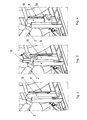
- a holding device 1 for a bicycle 2 is part of a motor vehicle 3 of the type passenger cars, of which only a Heckendteil 4 is shown.
- the rear end part 4 is provided with an opening 5, via which the holding device 1 can be moved from a position of rest sunk in a storage space 6 of the motor vehicle 3 into an extended operating position Bst.
- the opening 5 is covered by a cover 7, which is integrated into the mold structure of the rear end part 4.
- first and second receiving elements 8 and 9 Connected to the holding device 1 are first and second receiving elements 8 and 9, which are pivoted from a horizontal position (not shown) into a vertical position Stv.
- the first receiving element 8 is designed in the manner of a tubular holody, in which a moving in an upright position Pa Crank arm 10 of a treadle 11 of transverse to the vehicle longitudinal direction AA running bicycle 2 is inserted; Another crank arm of a second bicycle can be introduced into the second receiving element 9 -Fig. 1-.
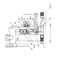
- the crank arm 10 is at least partially by walls 12, 13 and 14 -Fig. 9- of the first receiving element 8 surrounded, and it is fixed by means of an adjusting device 15 and a stop member 16 of the receiving element 8. At the stop member 16 of the crank arm 10 is applied, wherein the adjusting device 15 is effective in the transverse direction BB to the crank arm 10.
- the adjusting device 15 has a first actuator 17 and a second actuator 18, which are supported on opposite sides KaS1 and KaS2 of the crank arm 10, in support of the crank arm 10 on the stop member 16. At least the first actuator 17 in the height direction CC of Receiving element 8 made adjustable, so that the two actuators 17 and 18 are aligned relative to each other. In the exemplary embodiment, both actuators 17 and 18 are designed to be adjustable in the transverse direction B-B to the crank arm 10, which facilitates targeted by the opposing and horizontal arrows PF1, PF 2 and PF 3 clamping or fixing appropriately shaped crank arms different bikes.
- the first actuator 17 -Fig. 8- has a in the height direction CC of the receiving element 8 movable support member 19, which is supported on an inner side 20 of the receiving element 8 and is provided with a clamping screw 21 which is screwed into a thread 22 of the support member 19.
- the support member 19 is formed by an approximately U-shaped profile 23 having first bends 26 and 27 at free ends 24 and 25 of legs Sch1 and Sch2.
- the first bends 26 and 27 of the support member 19 engage behind second bends 28 and 29 of the receiving element 8, wherein at a distance from the first bends 26 and 27 on the support member 19 guide members 30 and 31 are provided, the easy guidance of the support member 19 along the second bends 28 and 29 allow.
- the clamping screw 21 is provided at a first end 32 with a first rotary handle 33 and at a second end 34 with a ball head 35 for ball socket 36 of a crank arm 10 toward the aligned pressure piece 37.
- a Provided support member Ste Between the crank arm 10 and pressure piece 37 is a Provided support member Ste, which is held on the pressing piece 37 in position and consists of an elastic material.
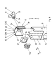
- the second actuator 18 -Fig. 9- is arranged on the wall 14 of the first receiving element 8, and it has a second rotary handle 38 and an adjusting element 39 which are rotationally symmetrical in shape and are connected by a snap-action connection acting in the axial direction Rax-Rax-not shown.
- the rotary handle 38 and the adjusting element 39 in the assembled state to a unit state an outer side 40 and an inner side 41 of the wall 14, which assembly is mounted in a bore 42 of the wall 14.
- the adjusting element 39 carries on a crank arm 10 facing side 43, a support member 44, and the adjusting element 39 is connected to the support member 44 via an axial screw 45, which is in operative connection with a threaded pin 46 of the support member 44.
- a compression spring 47 and an actuator 48 is effective between the adjusting element 39 and support member 44.
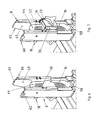
- the actuator 48 is an axial adjustment of the support member 44 in the transverse direction B-B feasible, which actuator 48, a first toothing 49 on the adjusting element 39 -Fig. 10- and a second toothing 50 on the support element 44 -Fig. 11- includes.
- the mutually facing teeth 49 and 50 are formed in such a way that the once set position of the second actuator 18 is maintained even under operational vibration of the motor vehicle.
- the teeth 49 and 50 each have three toothed portions 51, 52 and 53 or 54, 55 and 56, which are arranged distributed uniformly over the peripheries of the adjusting element 39 and the support member 44.
- the support member 44 made of resilient material, the latter is concave on the side facing the crank arm 57.
- the stop member 16 which is designed as a first insert 58 of the receiving element 8 made of elastic material, the crank arm 10 on the one hand in the transverse direction BB and on the other hand at a free end 59 of the crank arm 10.
- FIG. 5- supported.
- An upper end 60 of the first insert 58 forms an anti-rotation device for the support element 44 of the second actuator 18.
- Another second insert 61 of the receiving element 8 is attached to a free end 22 of the latter and acts because of resilient material, as protection against damage to high-quality surfaces-painted or chromed- the bicycle 1.
- the second insert 61 is by means of engaging behind devices 62 -. Form-fit effecting and resilient tongues 63 -Kraft gleich effect- held in the first receiving element 8 in position.
- the second insert 61 on the second rotary handle 38 facing side with a scale 64 -Fig. 9- provided, which serves for the targeted adjustment of the second actuator.
Landscapes
- Engineering & Computer Science (AREA)
- Mechanical Engineering (AREA)
- Fittings On The Vehicle Exterior For Carrying Loads, And Devices For Holding Or Mounting Articles (AREA)
- Steering Devices For Bicycles And Motorcycles (AREA)
Applications Claiming Priority (1)
| Application Number | Priority Date | Filing Date | Title |
|---|---|---|---|
| DE102006031691A DE102006031691A1 (de) | 2006-07-08 | 2006-07-08 | Halteeinrichtung für ein Fahrrad |
Publications (1)
| Publication Number | Publication Date |
|---|---|
| EP1876059A1 true EP1876059A1 (fr) | 2008-01-09 |
Family
ID=38523413
Family Applications (1)
| Application Number | Title | Priority Date | Filing Date |
|---|---|---|---|
| EP07012922A Ceased EP1876059A1 (fr) | 2006-07-08 | 2007-07-02 | Dispositif de retenue pour un vélo |
Country Status (4)
| Country | Link |
|---|---|
| US (1) | US20080007040A1 (fr) |
| EP (1) | EP1876059A1 (fr) |
| JP (1) | JP2008013173A (fr) |
| DE (1) | DE102006031691A1 (fr) |
Cited By (1)
| Publication number | Priority date | Publication date | Assignee | Title |
|---|---|---|---|---|
| EP4046873A1 (fr) | 2021-02-22 | 2022-08-24 | Manfred Hafele GmbH | Dispositif de support pour un véhicule automobile |
Families Citing this family (8)
| Publication number | Priority date | Publication date | Assignee | Title |
|---|---|---|---|---|
| KR101154526B1 (ko) * | 2009-09-30 | 2012-06-13 | 이든모터스 (주) | 차량용 자전거 케리어 |
| KR101090828B1 (ko) * | 2009-10-26 | 2011-12-08 | 현대자동차주식회사 | 차량용 캐리어의 보조판장치 |
| KR101151355B1 (ko) * | 2009-12-08 | 2012-06-08 | 이든모터스 (주) | 차량용 자전거 케리어 |
| KR101360446B1 (ko) | 2012-12-21 | 2014-02-11 | 현대자동차주식회사 | 차량용 자전거 캐리어 장치 |
| DE102015108554A1 (de) * | 2014-08-12 | 2016-02-18 | Westfalia-Automotive Gmbh | Stütze für einen Fahrradträger und Fahrradträger |
| KR101684170B1 (ko) * | 2015-09-11 | 2016-12-08 | 현대자동차주식회사 | 차량용 자전거 캐리어 시스템 |
| KR101776513B1 (ko) * | 2016-07-06 | 2017-09-08 | 현대자동차주식회사 | 차량용 캐리어 장치 |
| US11161460B2 (en) * | 2017-06-09 | 2021-11-02 | Seasucker, Llc | Reduced footprint vacuum mounted carriers for vehicles |
Citations (2)
| Publication number | Priority date | Publication date | Assignee | Title |
|---|---|---|---|---|
| EP0820902A1 (fr) * | 1996-07-23 | 1998-01-28 | Felua-groep | Dispositif pour serres d'une bicyclette |
| US5947357A (en) * | 1998-04-20 | 1999-09-07 | Surkin; Uri | Bicycle rack |
Family Cites Families (15)
| Publication number | Priority date | Publication date | Assignee | Title |
|---|---|---|---|---|
| US1223258A (en) * | 1916-05-09 | 1917-04-17 | Charles H Cooper | Bicycle-carrier. |
| US1772514A (en) * | 1928-09-19 | 1930-08-12 | Nels J Billstrom | Four-way blocking clamp |
| US2216858A (en) * | 1939-11-30 | 1940-10-08 | William H Steinbrink | Clamp |
| US2431400A (en) * | 1946-07-22 | 1947-11-25 | Nels J Iverson | Vehicle mounted carrier bracket |
| US3198408A (en) * | 1964-06-19 | 1965-08-03 | Lloyd E Benner | Support for a manikin form |
| FR2551705A1 (fr) * | 1983-09-12 | 1985-03-15 | Macorex Exploit Ets | Porte-bicyclette destine a equiper les barres porte-bagages d'un vehicule automobile |
| US4844431A (en) * | 1988-06-29 | 1989-07-04 | Arkansas Lousisiana Gas Company | Pneumatic gas meter test fixture |
| US5658119A (en) * | 1989-08-23 | 1997-08-19 | Softride, Inc. | Vehicle-mounted bicycle support rack |
| US4967508A (en) * | 1989-11-07 | 1990-11-06 | Reynolds Arthur A | Tree stand |
| US5025932A (en) * | 1990-01-25 | 1991-06-25 | Jay Lanny E | Secure bicycle rack and carrier |
| US5421495A (en) * | 1994-04-12 | 1995-06-06 | Inovative Bycicle Design Inc. | Vehicle roof rack |
| US5820002A (en) * | 1996-03-22 | 1998-10-13 | Yakima Products, Inc. | Lockable bicycle rack |
| US6626340B1 (en) * | 1997-06-13 | 2003-09-30 | Ronald J. Burgess | Load carrier |
| US20040108425A1 (en) * | 2002-12-06 | 2004-06-10 | Joel Alperson | Columnarly abuttable retail display brackets |
| US20070090142A1 (en) * | 2005-10-21 | 2007-04-26 | Louis Chuang | Concealable rack for carrying a bicycle on a vehicle |
-
2006
- 2006-07-08 DE DE102006031691A patent/DE102006031691A1/de not_active Withdrawn
-
2007
- 2007-06-28 US US11/770,278 patent/US20080007040A1/en not_active Abandoned
- 2007-07-02 EP EP07012922A patent/EP1876059A1/fr not_active Ceased
- 2007-07-03 JP JP2007175374A patent/JP2008013173A/ja active Pending
Patent Citations (2)
| Publication number | Priority date | Publication date | Assignee | Title |
|---|---|---|---|---|
| EP0820902A1 (fr) * | 1996-07-23 | 1998-01-28 | Felua-groep | Dispositif pour serres d'une bicyclette |
| US5947357A (en) * | 1998-04-20 | 1999-09-07 | Surkin; Uri | Bicycle rack |
Cited By (1)
| Publication number | Priority date | Publication date | Assignee | Title |
|---|---|---|---|---|
| EP4046873A1 (fr) | 2021-02-22 | 2022-08-24 | Manfred Hafele GmbH | Dispositif de support pour un véhicule automobile |
Also Published As
| Publication number | Publication date |
|---|---|
| JP2008013173A (ja) | 2008-01-24 |
| DE102006031691A1 (de) | 2008-01-10 |
| US20080007040A1 (en) | 2008-01-10 |
Similar Documents
| Publication | Publication Date | Title |
|---|---|---|
| EP1876059A1 (fr) | Dispositif de retenue pour un vélo | |
| EP2830927B1 (fr) | Corps d'enfichage pour un boulon de serrage | |
| EP2804801B1 (fr) | Colonne de direction pour un véhicule automobile | |
| EP3099527B1 (fr) | Actionneur pour un véhicule automobile, notamment pour un siège de véhicule automobile | |
| EP2780211B1 (fr) | Dispositif de fixation pour une colonne de direction réglable destinée à un véhicule à moteur | |
| EP2611673B1 (fr) | Colonne de direction pour un véhicule automobile | |
| DE102009053537A1 (de) | Schwenkbare Armlehne zur Verwendung in einem Fahrzeug | |
| DE102006031689A1 (de) | Trageeinrichtung für ein Fahrrad | |
| EP1910148A1 (fr) | Colonne de direction reglable destinee a un vehicule | |
| EP1149723B1 (fr) | Dispositif de stabilisation pour un tableau de bord à position réglable dans un véhicule | |
| DE102007003092B4 (de) | Fluidausgabevorrichtung für eine Scheiben- oder Scheinwerferwaschanlage eines Fahrzeuges | |
| DE29914042U1 (de) | Türscharnier für Kraftfahrzeugtüren mit integriertem Feststeller | |
| DE102008006102B4 (de) | Behälter zum Einbau in den Innenraum eines Kraftfahrzeuges | |
| EP2605939B1 (fr) | Dispositif d'essuie-glace | |
| DE4403506A1 (de) | Fahrzeugsitz | |
| EP1373015A1 (fr) | Siege de vehicule avec dispositif d'appui | |
| DE102005045927B4 (de) | Wischervorrichtung | |
| DE102006028570A1 (de) | Schließbügelanordnung insbesondere für einen Kraftwagen | |
| DE102020205817B3 (de) | Längseinsteller für einen Sitz, insbesondere Fahrzeugsitz | |
| DE102006053250A1 (de) | Vorrichtung zur Innenbetätigung einer Tür eines Automobils | |
| DE10016144A1 (de) | Vorrichtung zum Justieren einer Baugruppe, insbesondere einer Instrumententafel eines Kraftfahrzeuges | |
| EP3478545B1 (fr) | Pédalier pour un véhicule, en particulier un véhicule utilitaire | |
| EP1724427A2 (fr) | Dispositif de réglage de la position d'un rail de guidage d'un lève-vitre | |
| DE10003917A1 (de) | Halterung für eine Kühlerfigur eines Personenkraftwagens | |
| DE8816771U1 (de) | Schließvorrichtung |
Legal Events
| Date | Code | Title | Description |
|---|---|---|---|
| PUAI | Public reference made under article 153(3) epc to a published international application that has entered the european phase |
Free format text: ORIGINAL CODE: 0009012 |
|
| AK | Designated contracting states |
Kind code of ref document: A1 Designated state(s): AT BE BG CH CY CZ DE DK EE ES FI FR GB GR HU IE IS IT LI LT LU LV MC MT NL PL PT RO SE SI SK TR |
|
| AX | Request for extension of the european patent |
Extension state: AL BA HR MK YU |
|
| 17P | Request for examination filed |
Effective date: 20080626 |
|
| 17Q | First examination report despatched |
Effective date: 20080804 |
|
| AKX | Designation fees paid |
Designated state(s): DE FR GB IT |
|
| STAA | Information on the status of an ep patent application or granted ep patent |
Free format text: STATUS: THE APPLICATION HAS BEEN REFUSED |
|
| 18R | Application refused |
Effective date: 20100131 |