EP1876072A2 - Diebstahlsicherungssystem für ein Fahrzeug - Google Patents
Diebstahlsicherungssystem für ein Fahrzeug Download PDFInfo
- Publication number
- EP1876072A2 EP1876072A2 EP07252600A EP07252600A EP1876072A2 EP 1876072 A2 EP1876072 A2 EP 1876072A2 EP 07252600 A EP07252600 A EP 07252600A EP 07252600 A EP07252600 A EP 07252600A EP 1876072 A2 EP1876072 A2 EP 1876072A2
- Authority
- EP
- European Patent Office
- Prior art keywords
- portable device
- lock controller
- section
- information
- lock
- Prior art date
- Legal status (The legal status is an assumption and is not a legal conclusion. Google has not performed a legal analysis and makes no representation as to the accuracy of the status listed.)
- Granted
Links
Images


Classifications
-
- G—PHYSICS
- G07—CHECKING-DEVICES
- G07C—TIME OR ATTENDANCE REGISTERS; REGISTERING OR INDICATING THE WORKING OF MACHINES; GENERATING RANDOM NUMBERS; VOTING OR LOTTERY APPARATUS; ARRANGEMENTS, SYSTEMS OR APPARATUS FOR CHECKING NOT PROVIDED FOR ELSEWHERE
- G07C9/00—Individual registration on entry or exit
- G07C9/00174—Electronically operated locks; Circuits therefor; Nonmechanical keys therefor, e.g. passive or active electrical keys or other data carriers without mechanical keys
- G07C9/00817—Electronically operated locks; Circuits therefor; Nonmechanical keys therefor, e.g. passive or active electrical keys or other data carriers without mechanical keys where the code of the lock can be programmed
-
- B—PERFORMING OPERATIONS; TRANSPORTING
- B60—VEHICLES IN GENERAL
- B60R—VEHICLES, VEHICLE FITTINGS, OR VEHICLE PARTS, NOT OTHERWISE PROVIDED FOR
- B60R25/00—Fittings or systems for preventing or indicating unauthorised use or theft of vehicles
- B60R25/20—Means to switch the anti-theft system on or off
- B60R25/24—Means to switch the anti-theft system on or off using electronic identifiers containing a code not memorised by the user
-
- G—PHYSICS
- G07—CHECKING-DEVICES
- G07C—TIME OR ATTENDANCE REGISTERS; REGISTERING OR INDICATING THE WORKING OF MACHINES; GENERATING RANDOM NUMBERS; VOTING OR LOTTERY APPARATUS; ARRANGEMENTS, SYSTEMS OR APPARATUS FOR CHECKING NOT PROVIDED FOR ELSEWHERE
- G07C9/00—Individual registration on entry or exit
- G07C9/00174—Electronically operated locks; Circuits therefor; Nonmechanical keys therefor, e.g. passive or active electrical keys or other data carriers without mechanical keys
- G07C9/00309—Electronically operated locks; Circuits therefor; Nonmechanical keys therefor, e.g. passive or active electrical keys or other data carriers without mechanical keys operated with bidirectional data transmission between data carrier and locks
-
- B—PERFORMING OPERATIONS; TRANSPORTING
- B60—VEHICLES IN GENERAL
- B60R—VEHICLES, VEHICLE FITTINGS, OR VEHICLE PARTS, NOT OTHERWISE PROVIDED FOR
- B60R2325/00—Indexing scheme relating to vehicle anti-theft devices
- B60R2325/30—Vehicles applying the vehicle anti-theft devices
- B60R2325/306—Motorcycles
Definitions
- the present invention relates to a technology for registering ID information of a portable device carried by a user of a vehicle having a robbery prevention system and a vehicle having the robbery prevention system.
- an immobilizer system which authenticates a key inserted into a key cylinder based on ID information electronically provided for the key
- a so-called smart key system which authenticates a portable device carried by a user of a vehicle based on ID information wirelessly received from the portable device have been more widely used as systems for securely preventing robbery or theft of vehicles.
- a lock controller for performing the authentication process of the portable device or the key stores ID information of the portable device or the key in advance.
- ID information For registration of ID information, a specialized registration device is usually connected with the lock controller, and the ID information is inputted from the registration device to the lock controller.
- a user of the robbery prevention system is required to ask a specialist having the registration device to register the ID information at the time of replacement of the lock controller, and therefore the robbery prevention system is unsatisfactory from the viewpoint of convenience.
- JP-A-8-150898 A robbery prevention system which seeks to overcome this drawback is disclosed in JP-A-8-150898 .
- This prior art system stores ID information in an engine controller as well as a lock controller. According to this system, ID information is transmitted from the engine controller to the lock controller at the time of replacement of the lock controller to register the ID information on the lock controller. Thus, no special registration device is needed.
- the robbery prevention system disclosed in JP-A-8-150898 does not fully overcome the problem of inconvenience.
- ID information identical to ID information of a key is transmitted from the engine controller to a new lock controller and stored therein when the key is inserted into a key cylinder after replacement of the previous lock controller.
- the key needs to be inserted into the key cylinder for registration of the ID information, which operation is rather complicated and troublesome.
- the invention has been developed in an attempt to solve the above problems. It is an object of the invention to provide a robbery prevention system capable of simplifying registration of ID information at the time of replacement of a lock controller, and a vehicle having the robbery prevention system.
- a robbery prevention system comprising:
- a robbery prevention system comprising:
- the searching and storing means transmits the response requiring signal to search the portable device.
- the searching and storing means transmits the response requiring signal to search the portable device.
- the ID information is information each of which is allocated to the corresponding portable device in advance.
- an operation device is further provided, and the control target device controlled by the lock controller restricts operation of the operation device.
- the operation of the operation device is restricted when the control target device controlled by the lock controller is locked, and the operation of the operation device is allowed when the control target device controlled by the lock controller is unlocked to release the restriction by the control target device.
- the lock controller further includes detecting means that detects replacement of the lock controller.
- the searching and storing means stores the ID information of the portable device having transmitted the response signal to the response requiring signal at the time of replacement of the lock controller.
- the detecting means may judge that the lock controller has been replaced when the memory means of the lock controller does not have the ID information.
- the searching and storing means of the lock controller stores a predetermined number of the ID information in the memory means.
- security for registration of the portable device improves.
- the auxiliary controller further includes backup renewing means that renews the ID information stored in the memory means of the auxiliary controller as backup data according to predetermined timing.
- new ID information can be registered on the lock controller when the lock controller is replaced with new one.
- a vehicle comprising a robbery prevention system according to the first or second aspects.
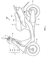
- Fig. 1 is a side view of a motorcycle 100 including a robbery prevention system 1 according to an embodiment the invention.
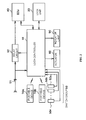
- Fig. 2 is a block diagram showing the structure of the robbery prevention system 1.
- the motorcycle 100 includes the robbery prevention system 1, an actuator 60, an engine 2, and a steering shaft 3.
- the steering shaft 3 extends diagonally downward, and has a handlebar 5 at the upper end and a front wheel 7a at the lower end.
- the steering shaft 3 is locked by a lock mechanism 3a in such a condition that the rotation of the steering shaft 3 is restricted at the time of stop of the vehicle.
- the engine 2 is disposed in the central lower region of the vehicle body, and the driving force of the engine 2 is transmitted to a rear wheel 7b via a driving force transmission mechanism 6.
- An openable and closable seat 8 is disposed above the engine 2, and a storage space (not shown) is provided below the seat 8.
- a lock mechanism 8a is provided to restrict opening and closing of the seat 8 when the seat 8 is at a close position.
- the actuator 60 actuates the lock mechanism 8a to restrict or allow opening and closing of the seat 8.
- a solenoid valve which locks or unlocks a lock mechanism of a console box or the like may be provided as an actuator.
- the robbery prevention system 1 includes a lock controller 10, a lock unit (auxiliary controller) 30, an engine control unit (ECU) 40, a switch group 50 constituted by a plurality of switches, portable devices 70A and 70B, and an indicator lamp 90.
- the indicator lamp 90 is an LED (light emitting diode) provided on an instrument panel, for example.
- the indicator lamp 90 is turned on by power supplied from the lock controller 10, and notifies a rider about errors or the like caused in the processes performed by the lock controller 10.
- the switch group 50 includes a plurality of switches such as a starter switch 50a, a sensor-type switch 50b used by the rider to open and close the console box, and a sensor-type switch 50n to release the lock of the seat 8. These switches transmit signals to the lock controller 10 in accordance with the switch operations performed by the user.
- the lock controller 10 retains ID (identification) information provided exclusively for each of the portable devices 70A and 70B (hereinafter referred to as portable device ID), and authenticates the portable device present within a predetermined detection range based on the portable device ID retained by the lock controller 10 and the portable device ID received from the portable device present within the detection range.
- portable device ID ID
- the lock controller 10 locks or unlocks control target devices (lock mechanism 8a, lock mechanism 3a, and ECU 40 in this example) mounted on the vehicle.
- the motorcycle 100 has operation devices (steering shaft 3, seat 8, ECU 40 in this example), and operations of the operation devices are restricted by the control target devices. The operations of the operation devices are restricted by the control target devices when the control target devices are locked by the lock controller 10.
- the operations of the operation devices are allowed when the control target devices are unlocked by the lock controller 10 to release the restriction by the control target devices.
- the opening and closing of the seat 8 or the rotation of the steering shaft 3 is restricted when the lock mechanism 8a or the lock mechanism 3a is locked by the lock controller 10
- the opening and closing of the seat 8 or the rotation of the steering shaft 3 is allowed when the lock mechanism 8a or the lock mechanism 3a is unlocked by the lock controller 10.
- the ECU 40 is locked and the start of the engine 2 is restricted when power supply to the ECU 40 is cut off by the lock controller 10.
- the engine 2 is allowed to start when power is supplied to the ECU 40 by the lock controller 10.
- the portable device IDs of the portable devices 70A and 70B are information each of which is allocated to the corresponding portable device in advance so as to identify each of the portable devices.
- the portable device IDs are established for the respective portable devices in their manufacturing process, for example.
- the lock controller 10 is a device newly mounted on the vehicle body after replacement of the previous lock controller, and does not have the portable device IDs of the portable devices 70A and 70B in the initial condition.
- the lock controller 10 acquires the portable device IDs by processes which will be described later.
- the lock unit 30 locks the lock mechanism 3a to restrict the rotation of the steering shaft 3 and unlocks the lock mechanism 3a to allow the rotation of the steering shaft 3 when the portable device 70A or device 70B is authenticated as the proper device from the result of the authentication process executed by the lock controller 10.
- the lock unit 30 retains backup data of the portable device IDs stored in the lock controller 10 and ID information provided exclusively for the lock controller 10 (hereinafter referred to as lock controller ID).
- the lock controller ID is information allocated to the lock controller 10 so as to distinguish the lock controller 10 from other lock controllers mounted on other vehicle bodies.
- the lock controller ID is established for each of the lock controllers in their manufacturing process, for example. While it is assumed that the lock unit 30 is an auxiliary controller which retains backup data in this embodiment, the ECU 40 may be used as the auxiliary controller, for example.
- the ECU 40 controls the fuel injection quantity supplied for the engine 2 and the injection timing by adjusting power supplied to an injector.
- the portable device 70A or 70B is authenticated as the proper device based on the result of the authentication process performed by the lock controller 10 under the condition that the starter switch 50a is turned on by the rider, power is supplied from a battery 91 to the ECU 40 through a relay circuit 92. By this process, the engine 2 is allowed to start.
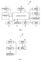
- Fig. 3 is a block diagram showing the structure of the lock controller 10.
- the lock controller 10 includes a control section 11, a memory section 12, a communication section 13, an actuator driving circuit 14, an input circuit 15, a display circuit 16, a power source supply circuit 17, interface sections 18 and 19, a relay driving circuit 20, and a power source circuit 21.
- the power source circuit 21 supplies power received from the battery 91 (see Fig. 2) to the respective components constituting the lock controller 10.
- Fig. 3 does not show connection lines for connecting the respective components with the power source circuit 21.
- the relay driving circuit 20 supplies or cuts off power to the relay circuit 92 in response to a signal inputted from control section 11.
- the power source supply circuit 17 supplies power received from the battery 91 via the power source circuit 21 to the lock unit 30.
- the display circuit 16 supplies power to the indicator lamp 90 in response to a signal inputted from the control section 11.
- the input circuit 15 converts analog signals inputted through the respective switches of the switch group 50 into digital signals and outputs the converted signals to the control section 11.
- the actuator driving circuit 14 supplies power to the actuator 60 in response to a signal inputted from the control section 11.
- the communication section 13 includes a wireless communication antenna.
- the communication section 13 converts and amplifies the digital signals inputted from the control section 11 into radio signals and transmits the radio signals.
- the communication section 13 also converts and amplifies the radio signals received from the portable devices 70A and 70B into digital signals, and outputs the digital signals to the control section 11.
- the interface section 19 outputs signals to the ECU 40 based on commands issued from the control section 11.
- the interface section 18 outputs signals to the lock unit 30 based on commands issued from the control section 11. For example, when the portable device is authenticated as a proper device based on the result of the authentication process for the portable device, signals indicating this fact are outputted from the interface sections 18 and 19.
- the control section 11 includes a CPU, and controls the entire components of the lock controller 10 by executing programs stored in the memory section 12. According to this embodiment, such processes are particularly performed for acquiring the portable device IDs stored in the lock unit 30 as backup data and storing the portable device IDs in the memory section 12 required when the new lock controller 10 is mounted on the vehicle body after replacement of the previous lock controller. The processes executed by the control section 11 will be discussed in detail later.
- the memory section 12 includes a readable and writable non-volatile memory, and has programs to be executed by the control section 11. According to this embodiment, the lock controller ID, the portable device IDs, and information indicating the number of the portable devices registered (hereinafter referred to as registration number information) are stored in the memory section 12 by the processes performed by the control section 11 as will described later.
- Fig. 4 is a block diagram showing the structure of the lock unit 30.
- the lock unit 30 includes a control section 31, a memory section 32, a lock mechanism driving circuit 33, a power source circuit 34, and an interface section 35.
- the interface section 35 outputs signals received from the interface section 18 of the lock controller 10 to the control section 31, and transmits signals to the interface section 18 based on commands issued from the control section 31.
- the power source circuit 34 supplies power received from the power source supply circuit 17 of the lock controller 10 to the respective parts of the lock unit 30.
- Fig. 4 does not show connection lines for connecting the respective components with the power source circuit 34.
- the lock mechanism driving circuit 33 supplies power to the actuator of the lock mechanism 3a of the steering shaft 3 in response to a signal inputted from the control circuit 31.
- the memory section 32 includes a readable and writable non-volatile memory, and retains programs to be executed by the control section 31.
- the memory section 32 also retains the lock controller ID, the portable device IDs, and the registration number information as backup data.
- the memory section 32 in the initial condition retains the portable device IDs and the like stored in the previous lock controller mounted on the vehicle body before replacement as backup data.
- the control section 31 includes a CPU, and controls the entire components of the lock unit 30 by executing the programs stored in the memory section 32. For example, the control section 31 performs processes for authorizing the lock controller 10 based on the lock controller ID transmitted from the lock controller 10, and renewing the backup data stored in the memory section 32. In this embodiment, the control section 31 particularly transmits the backup data stored in the memory section 32 to the lock controller 10 in response to requirement of the lock controller 10 at the time of registration of the portable device ID on the lock controller 10. The processes executed by the control section 31 will be described in detail later.
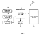
- Fig. 5 is a block diagram showing the structure of the portable device 70A.
- the portable device 70A includes a control section 71, a memory section 72, a communication section 73, a display section 74, and operation sections 75 and 76.
- the portable device 70B has a structure similar to that of the portable device 70A, and thus detailed explanation of the portable device 70B is not repeated herein.
- the operation sections 75 and 76 are switches which are operated by the rider and output signals to the control section 71 in accordance with the operation by the rider.
- the display section 74 is an LED, for example, and is turned on in response to a signal outputted from the control section 71.
- the communication section 73 includes a wireless communication antenna. The communication section 73 converts and amplifies digital signals inputted from the control section 71 into radio signals and transmits the radio signals. The communication section 73 also converts and amplifies the radio signals received from the lock controller 10 into digital signals and outputs the digital signals to the control section 71.
- the memory section 72 includes a readable and writable non-volatile memory, and retains programs to be executed by the control section 71.
- the memory section 72 also stores portable device IDs provided exclusively for each portable device in advance.
- the control section 71 including a CPU executes the programs stored in the memory section 72, and controls the entire components of the portable device 70. The processes performed by the control section 71 will be discussed in detail later.
- Fig. 6 is a function block diagram of the control section 11.
- the control section 11 includes a replacement detecting section 11a, an ID registration processing section 11b, an ID renewal processing section 11f, a backup renewal processing section 11g, an authentication processing section 11h, and an authentication process responding section 11i.
- the ID registration processing section 11b functions when the new lock controller 10 is mounted on the vehicle body after replacement of the previous lock controller.
- the ID renewal processing section 11f, the backup renewal processing section 11g, the authentication processing section 11h, and the authentication process responding section 11i function in the ordinary conditions after the process executed by the ID registration processing section 11b is completed.
- the processes performed by the respective sections are herein discussed in detail.
- the replacement detecting section 11a detects the condition where the lock controller 10 has been replaced with new one.
- the replacement detecting section 11a detects the replacement of the lock controller by the following method, for example.
- the replacement detecting section 11a searches the portable device ID in the memory area of the memory section 12, and judges that the new lock controller 10 has been mounted on the vehicle body by replacement of the lock controller when no portable device ID is detected.
- the replacement detecting section 11a searches the non registration information in the memory area of the memory section 12, and judges that the new lock controller 10 has been mounted on the vehicle body when the non registration information is detected.
- the replacement detecting section 11a may judge that the new lock controller 10 has been mounted on the vehicle body based on a signal inputted from the switch group 50 by predetermined switch operation executed by the operator.
- the ID registration processing section 11b executes re-storing process for acquiring the portable device IDs from the lock unit 30 and storing the portable device IDs in the memory section 12.
- the ID registration processing section 11b includes an ID acquisition processing section 11c, a portable device searching and storing section 11d, and a lock controller ID storing section 11e.
- the ID acquisition processing section 11c acquires the portable device IDs and lock controller ID. More specifically, the ID acquisition processing section 11c transmits a requirement signal for requiring transmission of the portable device IDs and the lock controller ID retained by the lock unit 30 as backup data to the lock unit 30. Then, the ID acquisition processing section 11c receives the portable device IDs and the lock controller ID transmitted from the lock unit 30 in response to the requirement signal.
- the portable device searching and storing section 11d transmits a response requiring signal for searching portable devices which have the portable device IDs received from the lock unit 30 (portable devices 70A and 70B in this example) and are present within a predetermined detection range (within a detection range of the lock controller 10 such as an area of several meters).
- a predetermined detection range within a detection range of the lock controller 10 such as an area of several meters.
- the portable device IDs of the portable devices having transmitted the response signals are stored in the memory section 12.
- the portable device searching and storing section 11d may register all the portable devices which have the portable device IDs stored in the lock unit 30 and have transmitted the response signals, or may register only a predetermined number of the portable devices.
- the lock controller ID storing section 11e stores the lock controller ID acquired by the ID acquisition processing section 11c from the lock unit 30 in the memory section 12. By this process, the lock controller 10 obtains the lock controller ID of the previous lock controller mounted on the vehicle body before replacement.
- the ID renewal processing section 11f stores the portable device ID of this portable device in the memory section 12. More specifically, when predetermined switch operation (hereinafter referred to as first operation) is initially performed by the operator, the ID renewal processing section 11f transmits a requirement signal for requiring portable device ID to a portable device not yet registered and present in the predetermined detection range. Then, the ID renewal processing section 11f receives the portable device ID transmitted from the portable device in response to the requirement signal. When predetermined switch operation different from the first operation (hereinafter referred to as second operation) is performed, the portable device IDs having been stored in the memory section 12 are deleted and thereafter the portable device ID of the unregistered portable device is stored in the memory section 12.
- predetermined switch operation hereinafter referred to as second operation
- the portable device ID of the unregistered portable device is added to the registered portable device IDs and stored in the memory section 12.
- the ID renewal processing section 11f further renews the registration number information.
- the backup renewal processing section 11g renews backup data retained by the lock unit 30 in accordance with predetermined timing.
- the predetermined timing herein includes the time when the start switch 50a is turned on by the rider, when new portable device ID is registered by the ID renewal processing section 11f, when predetermined time elapses from the previous renewal of the backup data, and other timing.
- the backup data renewed by the backup renewal processing section 11g is supplied for the re-storing process of the portable device ID to be executed later.
- the renewal process of the backup data is performed by the following method, for example.
- the backup renewal processing section 11g acquires the portable device IDs and the registration number information (hereinafter abbreviated as portable device information) stored as backup data from the lock unit 30. Then, the backup renewal processing section 11g compares the acquired portable device information and the portable device information stored in the memory section 12, and transmits the portable device information in the memory section 12 to the lock unit 30 when the information does not coincide with the other information (for example, when new portable device ID is added by the ID renewal processing section 11f). Then, the lock unit 30 retains the received portable device information as backup data. The process to be executed by the lock unit 30 will be discussed in detail later.
- the authentication processing section 11h authenticates a portable device present within the detection range when a predetermined switch contained in the switch group 50 (start switch 50a, for example) is turned on. When it is determined that this portable device is a proper portable device (portable device 70A or 70B in this embodiment) based on the authentication, the authentication processing section 11h unlocks or locks the control target devices. For example, the authentication processing section 11h transmits a signal indicating the judgment result to the lock unit 30 to release the locked condition of the lock mechanism 3a and allow the rotation of the steering shaft 3. Also, the authentication processing section 11h turns on the relay circuit 92 and supplies power to the ECU 40 to release the locked condition of the ECU 40 and bring the engine 2 into the starting condition. Furthermore, the authentication processing section 11h actuates the actuator 60 to release the locked condition of the lock mechanism 8a and thereby allow the opening and closing of the seat 8.
- the method of the authentication process performed by the authentication processing section 11h is a challenge and response method, for example.
- the authentication processing section 11h transmits the lock controller ID of the lock controller 10 and challenge data.
- the authentication processing section 11h calculates response data from the challenge data and the portable device ID stored in the memory section 12.
- the authentication processing section 11h compares the received response data and the response data previously calculated. When the response data coincides with the other response data, it is judged that the portable device having transmitted the response data has been already registered and therefore is a proper portable device.
- the method of authentication is not limited to the challenge and response method, but may be other methods such as plain text authentication.
- the authentication process responding section 11i responds to a signal transmitted from the lock unit 30 in the authentication process for authenticating the lock controller 10 by the lock unit 30. For example, when the lock unit 30 transmits a signal for requiring the lock controller ID, the authentication process responding section 11i reads the lock controller ID from the memory section 12 and transmits the lock controller ID to the lock unit 30 in response to the signal. When the authentication process performed by the lock unit 30 uses the challenge and response method, the authentication process responding section 11i creates response data from the challenge data received from the lock unit 30 and the lock controller ID, and transmits the response data to the lock unit 30. The authentication process performed by the lock unit 30 will be described in detail later.
- Fig. 7 is a function block diagram of the control section 31. As illustrated in this figure, the control section 31 includes an ID registration process responding section 31a, a backup renewal process responding section 31b, and an authentication processing section 31c as functional divisions.
- the ID registration process responding section 31a responds to a signal transmitted from the lock controller 10 in the portable device ID re-storing process discussed above. More specifically, when receiving a requirement signal requiring the portable device IDs and the lock controller ID from the lock controller 10, the ID registration process responding section 31a reads the portable device IDs and the lock controller ID from the memory section 32 and transmits these IDs to the lock controller 10 in response to the requirement signal.
- the ID registration process responding section 31a may encode the portable device IDs and the lock controller ID before transmission.
- the encoding method is an open key encoding method, for example.
- the lock controller 10 retains secret key data in advance.
- the ID registration process responding section 31a acquires open key data from the lock controller 10, encodes the portable device IDs and the lock controller ID using the open key data, and transmits the encoded IDs to the lock controller 10.
- the lock controller 10 decodes the signals transmitted from the ID registration process responding section 31a according to the secret key data to acquire the portable device IDs or the like.
- the encoding method may be a secret key encoding method.
- the backup renewal process responding section 31b responds to a signal transmitted from the lock controller 10 in the renewal process performed by the backup renewal processing section 11g discussed above. For example, when the backup data is required by the lock controller 10, the backup renewal process responding section 31b transmits the portable device information stored in the memory section 32 in response to the requirement. When portable device information is received from the lock controller 10 in the later process, the newly received portable device information is overwritten on the portable device information in the memory section 32 as new backup data.
- the authentication processing section 31c authenticates the lock controller 10 based on the lock controller ID. This authentication process is performed when the start switch 50a is turned on, when the portable device is authorized as a proper portable device based on the result of authentication process for the portable device executed by the lock controller 10 under the condition where the start switch 50a is turned on, and on other occasions, for example.
- the authentication process executed by the authentication processing section 31c uses the challenge and response method discussed above, for example. According to this method, the authentication processing section 31c creates challenge data and transmits the data to the lock controller 10. Simultaneously, the authentication processing section 31c calculates response data from the challenge data and the lock controller ID stored in the memory section 32 in advance. On the other hand, the authentication process responding section 11i of the lock controller 10 creates response data from the received challenge data and the lock controller ID stored in the memory section 12 and transmits the data to the lock unit 30. The authentication processing section 31c compares the response data received from the lock controller 10 and the response data previously calculated, and judges that the lock controller 10 is a proper device when the response data coincides with the other response data.
- Fig. 8 is a function block diagram of the control section 71. As illustrated in this figure, the control section 71 includes an ID registration process responding section 71a, and an authentication process responding section 71b as functional divisions.
- the ID registration process responding section 71a responds to a signal received from the lock controller 10 in the portable device ID re-storing process performed by the lock controller 10. More specifically, when receiving a response requiring signal from the lock controller 10, the ID registration process responding section 71a transmits a response signal to the lock controller 10 in response to the response requiring signal. In this case, the ID registration process responding section 71a may transmit the response signal when receiving the response requiring signal, or may transmit the response signal when a predetermined signal is inputted through the operation sections 75 and 76 after receipt of the response requiring signal and execution of predetermined switch operation by the operator.
- the authentication process responding section 71b responds to a signal received from the lock controller 10 in the authentication process performed by the lock controller 10. For example, when the authentication process method is the challenge and response method mentioned above, the authentication process responding section 71b creates response data from the challenge data received from the lock controller 10 and the portable device ID stored in the memory section 72 and transmits the response data to the lock controller 10.
- Fig. 9 shows an example of the portable device ID re-storing process.
- Fig. 10 shows an example of the backup data renewal process. Initially, the re-storing process is explained. It is assumed that only the portable device 70B is present within the detection range of the lock controller 10, and that the portable device 70A is absent in the detection range.
- the ID acquisition processing section 11c transmits a requirement signal requiring the portable device IDs and the lock controller ID to the lock unit 30 (S101).
- the ID registration process responding section 31a of the lock unit 30 having received the requirement signal reads the portable device IDs of the portable devices 70A and 70B and the lock controller ID stored in the memory section 32 as backup data, and transmits these IDs to the lock controller 10 (S102).
- the lock controller ID storing section 11e of the lock controller 10 stores the lock controller ID acquired from the lock unit 30 in the storage section 12 (S103).
- the portable device searching and storing section 11d selects one of the plural portable device IDs received from the lock unit 30 (portable device 70A in this case), and transmits the selected portable device ID and a response requiring signal (S104). Since the portable device 70A which is not present within the detection range as described above does not receive the response requiring signal, the lock controller 10 does not receive a response signal from the portable device 70A.
- the portable device searching and storing section 11d selects among the plural portable device IDs received from the lock unit 30 a portable device ID (portable device ID of portable device 70B in this case) different from the portable device ID previously selected (portable device ID of portable device 70A in this case), and transmits the selected portable device ID and a response requiring signal (S105).
- the portable device 70B since the portable device 70B is present within the detection range, the portable device 70B receives the portable device ID and the response requiring signal.
- the registration process responding section 71a of the portable device 70B compares the received portable device ID and the portable device ID of the portable device 70B stored in the memory section 72, and transmits a response signal to the lock controller 10 after confirming that the response requiring signal has been addressed to the portable device 70B (S106).
- the portable device searching and storing section 11d of the lock controller 10 having received the response signal reads the lock controller ID from the memory section 12, and transmits the lock controller ID to the portable device 70B (S107).
- the portable device searching and storing section 11a may transmit the portable device ID of the portable device 70B as well as the lock controller ID.
- the ID registration process responding section 71a of the portable device 70B may judge that the lock controller ID has been transmitted to the portable device 70B based on the portable device ID transmitted from the portable device searching and storing section 11a.
- the ID registration process responding section 71a of the portable device 70B stores the received lock controller ID in the memory section 72 (S108), and transmits a completion notifying signal indicating this fact to the lock controller 10 (S109).
- the portable device searching and storing section 11d stores the portable device ID of the portable device 70B in the memory section 12 (S110).
- the portable device searching and storing section 11d may store the registration number information indicating the number of the stored portable device IDs ("1" in this example) in the memory section 12.
- the lock unit 30 may authenticate the lock controller 10 based on manufacturer information having been stored in the memory section 12 during manufacture of the lock controller 10 to indicate that the lock controller 10 is a proper device.
- the lock unit 30 may transmit a signal indicating this fact to the lock controller 10 and then the lock controller 10 may transmit the requirement signal in S101.
- the backup renewal processing section 11g of the lock controller 10 transmits a requirement signal requiring transmission of the portable device information stored as backup data to the lock unit 30 when the start switch 50a is turned on by the rider, for example (S201).
- the backup renewal process responding section 31b of the lock unit 30 transmits the portable device information stored in the memory section 32 as backup data to the lock controller 10 (S202).
- the backup renewal processing section 11g compares the received portable device information and the portable device information stored in the memory section 12 (S203). In this example, since the portable device ID in the memory section 12 has been changed before the renewal process, the portable device ID does not coincide with the other portable device ID. Thus, the backup renewal processing section 11g transmits the portable device information in the memory section 12 to the lock unit 30 (S204).
- the backup renewal process responding section 31b When receiving the portable device information from the lock controller 10, the backup renewal process responding section 31b overwrites the newly received portable device information on the portable device information stored in the memory section 32 to obtain new backup data (S205). In this step, the backup renewal process responding section 31b may transmit a signal indicating completion of the renewal process of the backup data to the lock controller 10.
- Comparison between the backup data prior to renewal retained by the memory section 32 and the portable device information retained by the lock controller 10 may be performed by the lock unit 30.
- the backup renewal processing section 11g transmits the portable device information stored in the memory section 12 to the lock unit 30 according to predetermined timing.
- the backup renewal process responding section 31b compares the portable device information received from the lock controller 10 and the portable device information stored in the memory section 32 as backup data. When the portable device information does not coincide with the other portable device information, the newly received portable device information is overwritten on the stored portable device information.
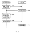
- Fig. 11 is a flowchart showing the flow of the processes executed by the replacement detecting section 11a and the ID registration processing section 11b.
- Fig. 11 is a flowchart showing the flow of the processes executed by the replacement detecting section 11a and the ID registration processing section 11b.
- the memory section 32 of the lock unit 30 retains an ID table sequentially storing a plurality of portable device IDs.
- the replacement detecting section 11a searches the memory area of the memory section 12 to judge whether the portable device ID has been stored (S301). When it is determined that the portable device ID has been already stored, the process ends.
- the ID acquisition processing section 11c transmits a requirement signal requiring transmission of the portable device IDs and the lock controller ID to the lock unit 30 (S302), and acquires a plurality of the portable device IDs and the lock controller ID returned from the lock unit 30 (S303).
- the portable device IDs are stored in the ID table discussed above and transmitted in the form of the table.
- the lock controller ID storing section 11e stores the lock controller ID in the memory section 12 (5304) .
- the portable device searching and storing section 11d establishes parameter i as initial value 1 (S305), and transmits the portable device ID stored ith in the ID table and a response requiring signal (S306). Subsequently, the portable device searching and storing section 11d judges whether a response signal has been received from the portable device retaining the portable device ID transmitted in S306 (S307). When it is determined that the response signal has not been received yet, the portable device searching and storing section 11d judges whether predetermined time has elapsed from the time of transmission of the response requiring signal (S308). When it is determined that the predetermined time has not elapsed yet, the process returns to S107 and the portable device searching and storing section 11d again judges whether the response signal has been received.
- the portable device searching and storing section 11d judges whether the response requiring signal has been transmitted to all the portable devices retaining the portable device IDs stored in the ID table (portable devices 70A and 70B in this example) (S309). When it is determined that the response requiring signal has been already transmitted to all the portable devices, it is judged that the portable devices 70A and 70B are not present within the detection range and the re-storing process of the portable device ID ends. In this process, the portable device searching and storing section 11d may turn on the indicator lamp 90 to notify the operator that the re-storing of the portable device ID has not been completed, for example.
- the portable device searching and storing section 11d increments the parameter i by one (S310) and the process returns to S306. Then, the portable device searching and storing section 11d again transmits the portable device ID stored ith in the ID table and the response requiring signal.
- the portable device searching and storing section 11d transmits the portable device ID of the portable device 70A or 70B having transmitted this response signal and a storage requiring signal requiring storage of the lock controller ID in the memory section 72 (S311). Then, the portable device searching and storing section 11d receives a completion notifying signal indicating that the lock controller ID has been stored in the memory section 72 in response to the storage requiring signal from the portable device 70A or 70B (S312) . Also, the portable device searching and storing section 11d stores the portable device ID of the portable device 70A or 70B having transmitted the response signal in the memory section 12 (S313). Then, the portable device searching and storing section 11d turns on the indicator lamp 90 in a predetermined manner to notify this fact to the operator (S314).
- the replacement detecting section 11a of the control section 11 detects replacement of the lock controller 10 with new one.
- the ID registration processing section 11b searches the portable device present within the predetermined detection range, and stores the portable device ID of this portable device in the memory section 12.
- the re-registration of the portable device ID needed when the lock controller is replaced can be facilitated.
Landscapes
- Engineering & Computer Science (AREA)
- Physics & Mathematics (AREA)
- General Physics & Mathematics (AREA)
- Mechanical Engineering (AREA)
- Computer Networks & Wireless Communication (AREA)
- Lock And Its Accessories (AREA)
- Emergency Alarm Devices (AREA)
- Burglar Alarm Systems (AREA)
Applications Claiming Priority (3)
| Application Number | Priority Date | Filing Date | Title |
|---|---|---|---|
| JP2006188174 | 2006-07-07 | ||
| JP2006263347 | 2006-09-27 | ||
| JP2007073484A JP5144947B2 (ja) | 2006-07-07 | 2007-03-20 | 車両の盗難防止システム、及び、盗難防止システムを搭載した車両 |
Publications (3)
| Publication Number | Publication Date |
|---|---|
| EP1876072A2 true EP1876072A2 (de) | 2008-01-09 |
| EP1876072A3 EP1876072A3 (de) | 2009-07-22 |
| EP1876072B1 EP1876072B1 (de) | 2010-05-12 |
Family
ID=38720349
Family Applications (1)
| Application Number | Title | Priority Date | Filing Date |
|---|---|---|---|
| EP20070252600 Active EP1876072B1 (de) | 2006-07-07 | 2007-06-27 | Diebstahlsicherungssystem für ein Fahrzeug |
Country Status (7)
| Country | Link |
|---|---|
| US (1) | US8514053B2 (de) |
| EP (1) | EP1876072B1 (de) |
| JP (1) | JP5144947B2 (de) |
| CN (1) | CN100595798C (de) |
| AT (1) | ATE467535T1 (de) |
| DE (1) | DE602007006379D1 (de) |
| TW (1) | TWI323705B (de) |
Cited By (1)
| Publication number | Priority date | Publication date | Assignee | Title |
|---|---|---|---|---|
| CN106600781A (zh) * | 2016-12-14 | 2017-04-26 | 北京拜克洛克科技有限公司 | 一种控制智能车锁关锁方法、装置、智能车锁及单车 |
Families Citing this family (14)
| Publication number | Priority date | Publication date | Assignee | Title |
|---|---|---|---|---|
| JP5222693B2 (ja) * | 2008-10-31 | 2013-06-26 | 本田技研工業株式会社 | 自動二輪車 |
| IN2014CN00497A (de) * | 2011-06-23 | 2015-04-03 | Honda Motor Co Ltd | |
| CN104954596B (zh) | 2011-07-25 | 2018-03-30 | 株式会社久保田 | 作业机以及作业机的设定变更系统 |
| JP6096773B2 (ja) | 2011-07-26 | 2017-03-15 | ゴゴロ インク | 電池などの電力貯蔵装置の認証、セキュリティ、及び制御用の装置、方法、及び物品 |
| ES2692524T3 (es) | 2011-07-26 | 2018-12-04 | Gogoro Inc. | Aparato, método y artículo para proporcionar datos de diagnóstico de vehículo |
| TWI517078B (zh) | 2011-07-26 | 2016-01-11 | 睿能創意公司 | 用於電力儲存器件收容空間之裝置、方法及物品 |
| JP6093514B2 (ja) * | 2012-05-10 | 2017-03-08 | 株式会社東海理化電機製作所 | 電子キー登録方法 |
| US9286167B2 (en) * | 2012-08-09 | 2016-03-15 | Panasonic Intellectual Property Corporation Of America | Communication device and management method for identification information item using communication device |
| TWI623677B (zh) * | 2014-09-10 | 2018-05-11 | 鴻海精密工業股份有限公司 | 車輛防盜控制系統及車輛防盜控制方法 |
| DE102015206628B4 (de) | 2015-04-14 | 2019-03-14 | Volkswagen Aktiengesellschaft | Hinweis auf berechtigte Authentifizierungsmedien für ein Fahrzeug |
| CN106600782B (zh) * | 2016-12-14 | 2019-07-26 | 江苏宏宝工具有限公司 | 一种控制智能车锁关锁方法、装置、智能车锁及单车 |
| WO2018095222A1 (en) * | 2016-11-25 | 2018-05-31 | Dongxia Datong (Beijing) Management And Consulting Co., Ltd. | Systems and methods for controlling a lock |
| JP6808579B2 (ja) * | 2017-06-07 | 2021-01-06 | 株式会社クボタ | 作業機の盗難防止システム、作業機の盗難防止方法及び作業機 |
| US11120657B2 (en) * | 2019-04-11 | 2021-09-14 | Townsteel, Inc. | Integrated lock management and smart device control system |
Family Cites Families (31)
| Publication number | Priority date | Publication date | Assignee | Title |
|---|---|---|---|---|
| US5252966A (en) * | 1987-05-21 | 1993-10-12 | Trw Inc. | Transmitter for remote control system for door locks |
| US4930011A (en) * | 1988-08-02 | 1990-05-29 | A. C. Nielsen Company | Method and apparatus for identifying individual members of a marketing and viewing audience |
| DE4333474C2 (de) * | 1993-08-20 | 1995-09-21 | Siemens Ag | Wegfahrsperre für ein Kraftfahrzeug |
| US5767784A (en) * | 1994-06-10 | 1998-06-16 | Delco Electronics Corporation | Initialization method for keyless entry system |
| JP3005175B2 (ja) * | 1994-09-28 | 2000-01-31 | 本田技研工業株式会社 | 車両盗難防止装置 |
| JP3525521B2 (ja) * | 1994-11-30 | 2004-05-10 | 株式会社デンソー | 車両等盗難防止装置 |
| JPH08150899A (ja) * | 1994-11-30 | 1996-06-11 | Nippon Denso Co Ltd | 車両用盗難防止装置 |
| JP3478428B2 (ja) | 1994-12-29 | 2003-12-15 | マツダ株式会社 | 車両用盗難防止装置 |
| JPH08277664A (ja) * | 1995-04-05 | 1996-10-22 | Oki Electric Ind Co Ltd | 電子キーシステム |
| JPH08284504A (ja) * | 1995-04-11 | 1996-10-29 | Nissan Motor Co Ltd | キーレスエントリー制御装置 |
| JPH0914109A (ja) | 1995-07-03 | 1997-01-14 | Calsonic Corp | エンジン不正始動防止装置 |
| US5933090A (en) * | 1996-08-23 | 1999-08-03 | Ut Automotive Dearborn, Inc. | Method and apparatus for field programming a remote control system |
| US5937065A (en) * | 1997-04-07 | 1999-08-10 | Eaton Corporation | Keyless motor vehicle entry and ignition system |
| FR2776096B1 (fr) * | 1998-03-12 | 2000-06-23 | Commissariat Energie Atomique | Procede et systeme de lecture d'un ensemble dynamique d'etiquettes portant des codes d'identification distincts |
| JP2000108848A (ja) * | 1998-10-02 | 2000-04-18 | Toyota Motor Corp | イモビライザ装置 |
| JP4237343B2 (ja) * | 1999-09-03 | 2009-03-11 | ヤマハモーターエレクトロニクス株式会社 | 車両の盗難防止方法および装置 |
| GB9925275D0 (en) * | 1999-10-27 | 1999-12-29 | Rover Group | A security system |
| JP2001301572A (ja) * | 2000-04-19 | 2001-10-31 | Denso Corp | 車載用ecuの識別コード付与方法と車載用ecu装置 |
| JP4078087B2 (ja) * | 2002-02-04 | 2008-04-23 | 株式会社東海理化電機製作所 | 電子キーシステム |
| JP3818168B2 (ja) * | 2002-02-15 | 2006-09-06 | 日産自動車株式会社 | 車両用電子キー装置および回転拘束装置 |
| JP3577482B2 (ja) * | 2002-02-15 | 2004-10-13 | 日産自動車株式会社 | 車載機器通信制御装置 |
| JP4172625B2 (ja) * | 2002-06-27 | 2008-10-29 | 富士通テン株式会社 | 盗難防止装置、及び盗難防止補助装置 |
| DE602004029113D1 (de) * | 2003-02-25 | 2010-10-28 | Canon Kk | Vorrichtung und Verfahren zum Verwalten von Artikeln |
| JP4227615B2 (ja) * | 2003-05-29 | 2009-02-18 | 富士通株式会社 | データリストア方法,情報処理装置およびデータリストアプログラム |
| US7068144B2 (en) * | 2003-07-21 | 2006-06-27 | Lear Corporation | Method and system for re-learning a key |
| JP2005251013A (ja) * | 2004-03-05 | 2005-09-15 | Digital Electronics Corp | 出退勤管理システムの端末装置、そのプログラムおよび記録媒体 |
| JP4528559B2 (ja) * | 2004-06-04 | 2010-08-18 | アルプス電気株式会社 | リモートキーレスエントリー装置 |
| JP2006054692A (ja) * | 2004-08-12 | 2006-02-23 | Canon Inc | 情報処理装置およびその制御方法 |
| US20080024267A1 (en) * | 2005-03-02 | 2008-01-31 | Magnadyne Corporation | Forced arming |
| JP4598567B2 (ja) * | 2005-03-07 | 2010-12-15 | 本田技研工業株式会社 | 車両の盗難防止システム |
| JP4777396B2 (ja) * | 2008-07-01 | 2011-09-21 | 三菱電機株式会社 | エンジン制御装置 |
-
2007
- 2007-03-20 JP JP2007073484A patent/JP5144947B2/ja active Active
- 2007-05-29 TW TW96119163A patent/TWI323705B/zh active
- 2007-06-27 EP EP20070252600 patent/EP1876072B1/de active Active
- 2007-06-27 AT AT07252600T patent/ATE467535T1/de not_active IP Right Cessation
- 2007-06-27 DE DE200760006379 patent/DE602007006379D1/de active Active
- 2007-07-05 CN CN200710127594A patent/CN100595798C/zh active Active
- 2007-07-05 US US11/773,671 patent/US8514053B2/en active Active
Cited By (2)
| Publication number | Priority date | Publication date | Assignee | Title |
|---|---|---|---|---|
| CN106600781A (zh) * | 2016-12-14 | 2017-04-26 | 北京拜克洛克科技有限公司 | 一种控制智能车锁关锁方法、装置、智能车锁及单车 |
| CN106600781B (zh) * | 2016-12-14 | 2019-03-08 | 江苏宏宝工具有限公司 | 一种控制智能车锁关锁方法、装置、智能车锁及单车 |
Also Published As
| Publication number | Publication date |
|---|---|
| DE602007006379D1 (de) | 2010-06-24 |
| TWI323705B (en) | 2010-04-21 |
| TW200806514A (en) | 2008-02-01 |
| EP1876072A3 (de) | 2009-07-22 |
| ATE467535T1 (de) | 2010-05-15 |
| US20080012683A1 (en) | 2008-01-17 |
| JP2008106590A (ja) | 2008-05-08 |
| US8514053B2 (en) | 2013-08-20 |
| EP1876072B1 (de) | 2010-05-12 |
| CN100595798C (zh) | 2010-03-24 |
| JP5144947B2 (ja) | 2013-02-13 |
| CN101101679A (zh) | 2008-01-09 |
Similar Documents
| Publication | Publication Date | Title |
|---|---|---|
| EP1876072B1 (de) | Diebstahlsicherungssystem für ein Fahrzeug | |
| US8884739B2 (en) | Vehicle security apparatus and system which prevents unauthorized use of a vehicle by immobilization | |
| EP1690761B1 (de) | Diebstahlprävention-System eines Freizeitfahrzeug | |
| JP4598567B2 (ja) | 車両の盗難防止システム | |
| US7667348B2 (en) | Vehicle theft prevention device | |
| US8102249B2 (en) | Starting control apparatus and starting control method | |
| JPH1081201A (ja) | 機関始動制御装置 | |
| KR19980033057A (ko) | 차량 도난 방지 시스템 | |
| EP1724167B1 (de) | Fahrzeugsteuerungsvorrichtung für ein Spreitzsitz-Fahrzeug | |
| JPH08268228A (ja) | 車両盗難防止装置 | |
| US7402920B2 (en) | Engine start controlling system | |
| JP5599759B2 (ja) | 始動制御装置 | |
| CN1815011B (zh) | 车辆的起动控制装置及起动控制方法 | |
| EP1724166B1 (de) | Fahrzeugsteuerungsvorrichtung für Spreitzsitz-Fahrzeug | |
| JP2006213247A5 (de) | ||
| US6297567B1 (en) | Engine control system and vehicular anti-theft system | |
| JP2003148018A (ja) | 車両用遠隔操作システムにおける固有コード登録方法 | |
| JP5144946B2 (ja) | 車両の盗難防止システム、及び、盗難防止システムを搭載した車両 | |
| JP2008084120A (ja) | 電子制御装置 | |
| KR100706448B1 (ko) | 차량 도난 방지를 위한 엔진 ecu의 시동 제어방법 | |
| JP2012148602A (ja) | 車両盗難防止装置 | |
| JP5093516B2 (ja) | 車両用盗難防止装置 | |
| KR101315745B1 (ko) | 이모빌라이저 시스템의 키 등록 방법 | |
| KR20060057680A (ko) | 차량 도난방지 시스템의 비상시동 장치 및 방법 | |
| KR100757583B1 (ko) | 자동차용 이모빌라이져 시스템의 제어방법 |
Legal Events
| Date | Code | Title | Description |
|---|---|---|---|
| PUAI | Public reference made under article 153(3) epc to a published international application that has entered the european phase |
Free format text: ORIGINAL CODE: 0009012 |
|
| 17P | Request for examination filed |
Effective date: 20070704 |
|
| AK | Designated contracting states |
Kind code of ref document: A2 Designated state(s): AT BE BG CH CY CZ DE DK EE ES FI FR GB GR HU IE IS IT LI LT LU LV MC MT NL PL PT RO SE SI SK TR |
|
| AX | Request for extension of the european patent |
Extension state: AL BA HR MK YU |
|
| PUAL | Search report despatched |
Free format text: ORIGINAL CODE: 0009013 |
|
| AK | Designated contracting states |
Kind code of ref document: A3 Designated state(s): AT BE BG CH CY CZ DE DK EE ES FI FR GB GR HU IE IS IT LI LT LU LV MC MT NL PL PT RO SE SI SK TR |
|
| AX | Request for extension of the european patent |
Extension state: AL BA HR MK RS |
|
| GRAP | Despatch of communication of intention to grant a patent |
Free format text: ORIGINAL CODE: EPIDOSNIGR1 |
|
| GRAS | Grant fee paid |
Free format text: ORIGINAL CODE: EPIDOSNIGR3 |
|
| AKX | Designation fees paid |
Designated state(s): AT BE BG CH CY CZ DE DK EE ES FI FR GB GR HU IE IS IT LI LT LU LV MC MT NL PL PT RO SE SI SK TR |
|
| GRAA | (expected) grant |
Free format text: ORIGINAL CODE: 0009210 |
|
| AK | Designated contracting states |
Kind code of ref document: B1 Designated state(s): AT BE BG CH CY CZ DE DK EE ES FI FR GB GR HU IE IS IT LI LT LU LV MC MT NL PL PT RO SE SI SK TR |
|
| REG | Reference to a national code |
Ref country code: GB Ref legal event code: FG4D |
|
| REG | Reference to a national code |
Ref country code: CH Ref legal event code: EP |
|
| REG | Reference to a national code |
Ref country code: IE Ref legal event code: FG4D |
|
| REF | Corresponds to: |
Ref document number: 602007006379 Country of ref document: DE Date of ref document: 20100624 Kind code of ref document: P |
|
| REG | Reference to a national code |
Ref country code: DE Ref legal event code: R096 Ref document number: 602007006379 Country of ref document: DE Effective date: 20100624 |
|
| REG | Reference to a national code |
Ref country code: NL Ref legal event code: VDEP Effective date: 20100512 |
|
| LTIE | Lt: invalidation of european patent or patent extension |
Effective date: 20100512 |
|
| PG25 | Lapsed in a contracting state [announced via postgrant information from national office to epo] |
Ref country code: ES Free format text: LAPSE BECAUSE OF FAILURE TO SUBMIT A TRANSLATION OF THE DESCRIPTION OR TO PAY THE FEE WITHIN THE PRESCRIBED TIME-LIMIT Effective date: 20100823 Ref country code: SE Free format text: LAPSE BECAUSE OF FAILURE TO SUBMIT A TRANSLATION OF THE DESCRIPTION OR TO PAY THE FEE WITHIN THE PRESCRIBED TIME-LIMIT Effective date: 20100512 Ref country code: NL Free format text: LAPSE BECAUSE OF FAILURE TO SUBMIT A TRANSLATION OF THE DESCRIPTION OR TO PAY THE FEE WITHIN THE PRESCRIBED TIME-LIMIT Effective date: 20100512 Ref country code: LT Free format text: LAPSE BECAUSE OF FAILURE TO SUBMIT A TRANSLATION OF THE DESCRIPTION OR TO PAY THE FEE WITHIN THE PRESCRIBED TIME-LIMIT Effective date: 20100512 |
|
| PG25 | Lapsed in a contracting state [announced via postgrant information from national office to epo] |
Ref country code: FI Free format text: LAPSE BECAUSE OF FAILURE TO SUBMIT A TRANSLATION OF THE DESCRIPTION OR TO PAY THE FEE WITHIN THE PRESCRIBED TIME-LIMIT Effective date: 20100512 Ref country code: IS Free format text: LAPSE BECAUSE OF FAILURE TO SUBMIT A TRANSLATION OF THE DESCRIPTION OR TO PAY THE FEE WITHIN THE PRESCRIBED TIME-LIMIT Effective date: 20100912 Ref country code: LV Free format text: LAPSE BECAUSE OF FAILURE TO SUBMIT A TRANSLATION OF THE DESCRIPTION OR TO PAY THE FEE WITHIN THE PRESCRIBED TIME-LIMIT Effective date: 20100512 Ref country code: SI Free format text: LAPSE BECAUSE OF FAILURE TO SUBMIT A TRANSLATION OF THE DESCRIPTION OR TO PAY THE FEE WITHIN THE PRESCRIBED TIME-LIMIT Effective date: 20100512 Ref country code: AT Free format text: LAPSE BECAUSE OF FAILURE TO SUBMIT A TRANSLATION OF THE DESCRIPTION OR TO PAY THE FEE WITHIN THE PRESCRIBED TIME-LIMIT Effective date: 20100512 |
|
| PG25 | Lapsed in a contracting state [announced via postgrant information from national office to epo] |
Ref country code: PL Free format text: LAPSE BECAUSE OF FAILURE TO SUBMIT A TRANSLATION OF THE DESCRIPTION OR TO PAY THE FEE WITHIN THE PRESCRIBED TIME-LIMIT Effective date: 20100512 Ref country code: CY Free format text: LAPSE BECAUSE OF FAILURE TO SUBMIT A TRANSLATION OF THE DESCRIPTION OR TO PAY THE FEE WITHIN THE PRESCRIBED TIME-LIMIT Effective date: 20100519 |
|
| PG25 | Lapsed in a contracting state [announced via postgrant information from national office to epo] |
Ref country code: MC Free format text: LAPSE BECAUSE OF NON-PAYMENT OF DUE FEES Effective date: 20100630 Ref country code: DK Free format text: LAPSE BECAUSE OF FAILURE TO SUBMIT A TRANSLATION OF THE DESCRIPTION OR TO PAY THE FEE WITHIN THE PRESCRIBED TIME-LIMIT Effective date: 20100512 Ref country code: EE Free format text: LAPSE BECAUSE OF FAILURE TO SUBMIT A TRANSLATION OF THE DESCRIPTION OR TO PAY THE FEE WITHIN THE PRESCRIBED TIME-LIMIT Effective date: 20100512 Ref country code: PT Free format text: LAPSE BECAUSE OF FAILURE TO SUBMIT A TRANSLATION OF THE DESCRIPTION OR TO PAY THE FEE WITHIN THE PRESCRIBED TIME-LIMIT Effective date: 20100913 |
|
| PG25 | Lapsed in a contracting state [announced via postgrant information from national office to epo] |
Ref country code: RO Free format text: LAPSE BECAUSE OF FAILURE TO SUBMIT A TRANSLATION OF THE DESCRIPTION OR TO PAY THE FEE WITHIN THE PRESCRIBED TIME-LIMIT Effective date: 20100512 Ref country code: BE Free format text: LAPSE BECAUSE OF FAILURE TO SUBMIT A TRANSLATION OF THE DESCRIPTION OR TO PAY THE FEE WITHIN THE PRESCRIBED TIME-LIMIT Effective date: 20100512 Ref country code: SK Free format text: LAPSE BECAUSE OF FAILURE TO SUBMIT A TRANSLATION OF THE DESCRIPTION OR TO PAY THE FEE WITHIN THE PRESCRIBED TIME-LIMIT Effective date: 20100512 Ref country code: CZ Free format text: LAPSE BECAUSE OF FAILURE TO SUBMIT A TRANSLATION OF THE DESCRIPTION OR TO PAY THE FEE WITHIN THE PRESCRIBED TIME-LIMIT Effective date: 20100512 |
|
| PLBE | No opposition filed within time limit |
Free format text: ORIGINAL CODE: 0009261 |
|
| STAA | Information on the status of an ep patent application or granted ep patent |
Free format text: STATUS: NO OPPOSITION FILED WITHIN TIME LIMIT |
|
| PG25 | Lapsed in a contracting state [announced via postgrant information from national office to epo] |
Ref country code: IT Free format text: LAPSE BECAUSE OF FAILURE TO SUBMIT A TRANSLATION OF THE DESCRIPTION OR TO PAY THE FEE WITHIN THE PRESCRIBED TIME-LIMIT Effective date: 20100512 |
|
| 26N | No opposition filed |
Effective date: 20110215 |
|
| PG25 | Lapsed in a contracting state [announced via postgrant information from national office to epo] |
Ref country code: GR Free format text: LAPSE BECAUSE OF FAILURE TO SUBMIT A TRANSLATION OF THE DESCRIPTION OR TO PAY THE FEE WITHIN THE PRESCRIBED TIME-LIMIT Effective date: 20100813 Ref country code: MT Free format text: LAPSE BECAUSE OF FAILURE TO SUBMIT A TRANSLATION OF THE DESCRIPTION OR TO PAY THE FEE WITHIN THE PRESCRIBED TIME-LIMIT Effective date: 20100512 Ref country code: IE Free format text: LAPSE BECAUSE OF NON-PAYMENT OF DUE FEES Effective date: 20100627 |
|
| REG | Reference to a national code |
Ref country code: DE Ref legal event code: R097 Ref document number: 602007006379 Country of ref document: DE Effective date: 20110214 Ref country code: DE Ref legal event code: R097 Ref document number: 602007006379 Country of ref document: DE Effective date: 20110215 |
|
| REG | Reference to a national code |
Ref country code: CH Ref legal event code: PL |
|
| PG25 | Lapsed in a contracting state [announced via postgrant information from national office to epo] |
Ref country code: LI Free format text: LAPSE BECAUSE OF NON-PAYMENT OF DUE FEES Effective date: 20110630 Ref country code: CH Free format text: LAPSE BECAUSE OF NON-PAYMENT OF DUE FEES Effective date: 20110630 |
|
| PG25 | Lapsed in a contracting state [announced via postgrant information from national office to epo] |
Ref country code: LU Free format text: LAPSE BECAUSE OF NON-PAYMENT OF DUE FEES Effective date: 20100627 Ref country code: HU Free format text: LAPSE BECAUSE OF FAILURE TO SUBMIT A TRANSLATION OF THE DESCRIPTION OR TO PAY THE FEE WITHIN THE PRESCRIBED TIME-LIMIT Effective date: 20101113 Ref country code: BG Free format text: LAPSE BECAUSE OF FAILURE TO SUBMIT A TRANSLATION OF THE DESCRIPTION OR TO PAY THE FEE WITHIN THE PRESCRIBED TIME-LIMIT Effective date: 20100512 |
|
| PG25 | Lapsed in a contracting state [announced via postgrant information from national office to epo] |
Ref country code: TR Free format text: LAPSE BECAUSE OF FAILURE TO SUBMIT A TRANSLATION OF THE DESCRIPTION OR TO PAY THE FEE WITHIN THE PRESCRIBED TIME-LIMIT Effective date: 20100512 |
|
| PG25 | Lapsed in a contracting state [announced via postgrant information from national office to epo] |
Ref country code: BG Free format text: LAPSE BECAUSE OF FAILURE TO SUBMIT A TRANSLATION OF THE DESCRIPTION OR TO PAY THE FEE WITHIN THE PRESCRIBED TIME-LIMIT Effective date: 20100812 |
|
| REG | Reference to a national code |
Ref country code: FR Ref legal event code: PLFP Year of fee payment: 10 |
|
| REG | Reference to a national code |
Ref country code: FR Ref legal event code: PLFP Year of fee payment: 11 |
|
| REG | Reference to a national code |
Ref country code: FR Ref legal event code: PLFP Year of fee payment: 12 |
|
| P01 | Opt-out of the competence of the unified patent court (upc) registered |
Effective date: 20230526 |
|
| PGFP | Annual fee paid to national office [announced via postgrant information from national office to epo] |
Ref country code: DE Payment date: 20250618 Year of fee payment: 19 |
|
| PGFP | Annual fee paid to national office [announced via postgrant information from national office to epo] |
Ref country code: GB Payment date: 20250618 Year of fee payment: 19 |
|
| PGFP | Annual fee paid to national office [announced via postgrant information from national office to epo] |
Ref country code: FR Payment date: 20250620 Year of fee payment: 19 |