EP1876080A2 - Système d'entraînement pour un chariot de manutention doté d'un moteur à combustion interne - Google Patents
Système d'entraînement pour un chariot de manutention doté d'un moteur à combustion interne Download PDFInfo
- Publication number
- EP1876080A2 EP1876080A2 EP07012652A EP07012652A EP1876080A2 EP 1876080 A2 EP1876080 A2 EP 1876080A2 EP 07012652 A EP07012652 A EP 07012652A EP 07012652 A EP07012652 A EP 07012652A EP 1876080 A2 EP1876080 A2 EP 1876080A2
- Authority
- EP
- European Patent Office
- Prior art keywords
- shaft
- gear
- drive system
- electric motor
- brake
- Prior art date
- Legal status (The legal status is an assumption and is not a legal conclusion. Google has not performed a legal analysis and makes no representation as to the accuracy of the status listed.)
- Granted
Links
Images


Classifications
-
- B—PERFORMING OPERATIONS; TRANSPORTING
- B60—VEHICLES IN GENERAL
- B60W—CONJOINT CONTROL OF VEHICLE SUB-UNITS OF DIFFERENT TYPE OR DIFFERENT FUNCTION; CONTROL SYSTEMS SPECIALLY ADAPTED FOR HYBRID VEHICLES; ROAD VEHICLE DRIVE CONTROL SYSTEMS FOR PURPOSES NOT RELATED TO THE CONTROL OF A PARTICULAR SUB-UNIT
- B60W20/00—Control systems specially adapted for hybrid vehicles
- B60W20/10—Controlling the power contribution of each of the prime movers to meet required power demand
-
- B—PERFORMING OPERATIONS; TRANSPORTING
- B60—VEHICLES IN GENERAL
- B60K—ARRANGEMENT OR MOUNTING OF PROPULSION UNITS OR OF TRANSMISSIONS IN VEHICLES; ARRANGEMENT OR MOUNTING OF PLURAL DIVERSE PRIME-MOVERS IN VEHICLES; AUXILIARY DRIVES FOR VEHICLES; INSTRUMENTATION OR DASHBOARDS FOR VEHICLES; ARRANGEMENTS IN CONNECTION WITH COOLING, AIR INTAKE, GAS EXHAUST OR FUEL SUPPLY OF PROPULSION UNITS IN VEHICLES
- B60K6/00—Arrangement or mounting of plural diverse prime-movers for mutual or common propulsion, e.g. hybrid propulsion systems comprising electric motors and internal combustion engines
- B60K6/20—Arrangement or mounting of plural diverse prime-movers for mutual or common propulsion, e.g. hybrid propulsion systems comprising electric motors and internal combustion engines the prime-movers consisting of electric motors and internal combustion engines, e.g. HEVs
- B60K6/22—Arrangement or mounting of plural diverse prime-movers for mutual or common propulsion, e.g. hybrid propulsion systems comprising electric motors and internal combustion engines the prime-movers consisting of electric motors and internal combustion engines, e.g. HEVs characterised by apparatus, components or means specially adapted for HEVs
- B60K6/36—Arrangement or mounting of plural diverse prime-movers for mutual or common propulsion, e.g. hybrid propulsion systems comprising electric motors and internal combustion engines the prime-movers consisting of electric motors and internal combustion engines, e.g. HEVs characterised by apparatus, components or means specially adapted for HEVs characterised by the transmission gearings
- B60K6/365—Arrangement or mounting of plural diverse prime-movers for mutual or common propulsion, e.g. hybrid propulsion systems comprising electric motors and internal combustion engines the prime-movers consisting of electric motors and internal combustion engines, e.g. HEVs characterised by apparatus, components or means specially adapted for HEVs characterised by the transmission gearings with the gears having orbital motion
-
- B—PERFORMING OPERATIONS; TRANSPORTING
- B60—VEHICLES IN GENERAL
- B60K—ARRANGEMENT OR MOUNTING OF PROPULSION UNITS OR OF TRANSMISSIONS IN VEHICLES; ARRANGEMENT OR MOUNTING OF PLURAL DIVERSE PRIME-MOVERS IN VEHICLES; AUXILIARY DRIVES FOR VEHICLES; INSTRUMENTATION OR DASHBOARDS FOR VEHICLES; ARRANGEMENTS IN CONNECTION WITH COOLING, AIR INTAKE, GAS EXHAUST OR FUEL SUPPLY OF PROPULSION UNITS IN VEHICLES
- B60K6/00—Arrangement or mounting of plural diverse prime-movers for mutual or common propulsion, e.g. hybrid propulsion systems comprising electric motors and internal combustion engines
- B60K6/20—Arrangement or mounting of plural diverse prime-movers for mutual or common propulsion, e.g. hybrid propulsion systems comprising electric motors and internal combustion engines the prime-movers consisting of electric motors and internal combustion engines, e.g. HEVs
- B60K6/22—Arrangement or mounting of plural diverse prime-movers for mutual or common propulsion, e.g. hybrid propulsion systems comprising electric motors and internal combustion engines the prime-movers consisting of electric motors and internal combustion engines, e.g. HEVs characterised by apparatus, components or means specially adapted for HEVs
- B60K6/40—Arrangement or mounting of plural diverse prime-movers for mutual or common propulsion, e.g. hybrid propulsion systems comprising electric motors and internal combustion engines the prime-movers consisting of electric motors and internal combustion engines, e.g. HEVs characterised by apparatus, components or means specially adapted for HEVs characterised by the assembly or relative disposition of components
-
- B—PERFORMING OPERATIONS; TRANSPORTING
- B60—VEHICLES IN GENERAL
- B60K—ARRANGEMENT OR MOUNTING OF PROPULSION UNITS OR OF TRANSMISSIONS IN VEHICLES; ARRANGEMENT OR MOUNTING OF PLURAL DIVERSE PRIME-MOVERS IN VEHICLES; AUXILIARY DRIVES FOR VEHICLES; INSTRUMENTATION OR DASHBOARDS FOR VEHICLES; ARRANGEMENTS IN CONNECTION WITH COOLING, AIR INTAKE, GAS EXHAUST OR FUEL SUPPLY OF PROPULSION UNITS IN VEHICLES
- B60K6/00—Arrangement or mounting of plural diverse prime-movers for mutual or common propulsion, e.g. hybrid propulsion systems comprising electric motors and internal combustion engines
- B60K6/20—Arrangement or mounting of plural diverse prime-movers for mutual or common propulsion, e.g. hybrid propulsion systems comprising electric motors and internal combustion engines the prime-movers consisting of electric motors and internal combustion engines, e.g. HEVs
- B60K6/42—Arrangement or mounting of plural diverse prime-movers for mutual or common propulsion, e.g. hybrid propulsion systems comprising electric motors and internal combustion engines the prime-movers consisting of electric motors and internal combustion engines, e.g. HEVs characterised by the architecture of the hybrid electric vehicle
- B60K6/44—Series-parallel type
- B60K6/445—Differential gearing distribution type
-
- B—PERFORMING OPERATIONS; TRANSPORTING
- B60—VEHICLES IN GENERAL
- B60K—ARRANGEMENT OR MOUNTING OF PROPULSION UNITS OR OF TRANSMISSIONS IN VEHICLES; ARRANGEMENT OR MOUNTING OF PLURAL DIVERSE PRIME-MOVERS IN VEHICLES; AUXILIARY DRIVES FOR VEHICLES; INSTRUMENTATION OR DASHBOARDS FOR VEHICLES; ARRANGEMENTS IN CONNECTION WITH COOLING, AIR INTAKE, GAS EXHAUST OR FUEL SUPPLY OF PROPULSION UNITS IN VEHICLES
- B60K6/00—Arrangement or mounting of plural diverse prime-movers for mutual or common propulsion, e.g. hybrid propulsion systems comprising electric motors and internal combustion engines
- B60K6/20—Arrangement or mounting of plural diverse prime-movers for mutual or common propulsion, e.g. hybrid propulsion systems comprising electric motors and internal combustion engines the prime-movers consisting of electric motors and internal combustion engines, e.g. HEVs
- B60K6/50—Architecture of the driveline characterised by arrangement or kind of transmission units
- B60K6/54—Transmission for changing ratio
- B60K6/547—Transmission for changing ratio the transmission being a stepped gearing
-
- B—PERFORMING OPERATIONS; TRANSPORTING
- B60—VEHICLES IN GENERAL
- B60L—PROPULSION OF ELECTRICALLY-PROPELLED VEHICLES; SUPPLYING ELECTRIC POWER FOR AUXILIARY EQUIPMENT OF ELECTRICALLY-PROPELLED VEHICLES; ELECTRODYNAMIC BRAKE SYSTEMS FOR VEHICLES IN GENERAL; MAGNETIC SUSPENSION OR LEVITATION FOR VEHICLES; MONITORING OPERATING VARIABLES OF ELECTRICALLY-PROPELLED VEHICLES; ELECTRIC SAFETY DEVICES FOR ELECTRICALLY-PROPELLED VEHICLES
- B60L15/00—Methods, circuits, or devices for controlling the traction-motor speed of electrically-propelled vehicles
- B60L15/20—Methods, circuits, or devices for controlling the traction-motor speed of electrically-propelled vehicles for control of the vehicle or its driving motor to achieve a desired performance, e.g. speed, torque, programmed variation of speed
- B60L15/2009—Methods, circuits, or devices for controlling the traction-motor speed of electrically-propelled vehicles for control of the vehicle or its driving motor to achieve a desired performance, e.g. speed, torque, programmed variation of speed for braking
-
- B—PERFORMING OPERATIONS; TRANSPORTING
- B60—VEHICLES IN GENERAL
- B60L—PROPULSION OF ELECTRICALLY-PROPELLED VEHICLES; SUPPLYING ELECTRIC POWER FOR AUXILIARY EQUIPMENT OF ELECTRICALLY-PROPELLED VEHICLES; ELECTRODYNAMIC BRAKE SYSTEMS FOR VEHICLES IN GENERAL; MAGNETIC SUSPENSION OR LEVITATION FOR VEHICLES; MONITORING OPERATING VARIABLES OF ELECTRICALLY-PROPELLED VEHICLES; ELECTRIC SAFETY DEVICES FOR ELECTRICALLY-PROPELLED VEHICLES
- B60L15/00—Methods, circuits, or devices for controlling the traction-motor speed of electrically-propelled vehicles
- B60L15/20—Methods, circuits, or devices for controlling the traction-motor speed of electrically-propelled vehicles for control of the vehicle or its driving motor to achieve a desired performance, e.g. speed, torque, programmed variation of speed
- B60L15/2054—Methods, circuits, or devices for controlling the traction-motor speed of electrically-propelled vehicles for control of the vehicle or its driving motor to achieve a desired performance, e.g. speed, torque, programmed variation of speed by controlling transmissions or clutches
-
- B—PERFORMING OPERATIONS; TRANSPORTING
- B60—VEHICLES IN GENERAL
- B60L—PROPULSION OF ELECTRICALLY-PROPELLED VEHICLES; SUPPLYING ELECTRIC POWER FOR AUXILIARY EQUIPMENT OF ELECTRICALLY-PROPELLED VEHICLES; ELECTRODYNAMIC BRAKE SYSTEMS FOR VEHICLES IN GENERAL; MAGNETIC SUSPENSION OR LEVITATION FOR VEHICLES; MONITORING OPERATING VARIABLES OF ELECTRICALLY-PROPELLED VEHICLES; ELECTRIC SAFETY DEVICES FOR ELECTRICALLY-PROPELLED VEHICLES
- B60L50/00—Electric propulsion with power supplied within the vehicle
- B60L50/10—Electric propulsion with power supplied within the vehicle using propulsion power supplied by engine-driven generators, e.g. generators driven by combustion engines
- B60L50/16—Electric propulsion with power supplied within the vehicle using propulsion power supplied by engine-driven generators, e.g. generators driven by combustion engines with provision for separate direct mechanical propulsion
-
- B—PERFORMING OPERATIONS; TRANSPORTING
- B60—VEHICLES IN GENERAL
- B60L—PROPULSION OF ELECTRICALLY-PROPELLED VEHICLES; SUPPLYING ELECTRIC POWER FOR AUXILIARY EQUIPMENT OF ELECTRICALLY-PROPELLED VEHICLES; ELECTRODYNAMIC BRAKE SYSTEMS FOR VEHICLES IN GENERAL; MAGNETIC SUSPENSION OR LEVITATION FOR VEHICLES; MONITORING OPERATING VARIABLES OF ELECTRICALLY-PROPELLED VEHICLES; ELECTRIC SAFETY DEVICES FOR ELECTRICALLY-PROPELLED VEHICLES
- B60L50/00—Electric propulsion with power supplied within the vehicle
- B60L50/50—Electric propulsion with power supplied within the vehicle using propulsion power supplied by batteries or fuel cells
- B60L50/60—Electric propulsion with power supplied within the vehicle using propulsion power supplied by batteries or fuel cells using power supplied by batteries
- B60L50/61—Electric propulsion with power supplied within the vehicle using propulsion power supplied by batteries or fuel cells using power supplied by batteries by batteries charged by engine-driven generators, e.g. series hybrid electric vehicles
-
- B—PERFORMING OPERATIONS; TRANSPORTING
- B60—VEHICLES IN GENERAL
- B60L—PROPULSION OF ELECTRICALLY-PROPELLED VEHICLES; SUPPLYING ELECTRIC POWER FOR AUXILIARY EQUIPMENT OF ELECTRICALLY-PROPELLED VEHICLES; ELECTRODYNAMIC BRAKE SYSTEMS FOR VEHICLES IN GENERAL; MAGNETIC SUSPENSION OR LEVITATION FOR VEHICLES; MONITORING OPERATING VARIABLES OF ELECTRICALLY-PROPELLED VEHICLES; ELECTRIC SAFETY DEVICES FOR ELECTRICALLY-PROPELLED VEHICLES
- B60L7/00—Electrodynamic brake systems for vehicles in general
- B60L7/10—Dynamic electric regenerative braking
- B60L7/14—Dynamic electric regenerative braking for vehicles propelled by AC motors
-
- B—PERFORMING OPERATIONS; TRANSPORTING
- B60—VEHICLES IN GENERAL
- B60W—CONJOINT CONTROL OF VEHICLE SUB-UNITS OF DIFFERENT TYPE OR DIFFERENT FUNCTION; CONTROL SYSTEMS SPECIALLY ADAPTED FOR HYBRID VEHICLES; ROAD VEHICLE DRIVE CONTROL SYSTEMS FOR PURPOSES NOT RELATED TO THE CONTROL OF A PARTICULAR SUB-UNIT
- B60W10/00—Conjoint control of vehicle sub-units of different type or different function
- B60W10/04—Conjoint control of vehicle sub-units of different type or different function including control of propulsion units
- B60W10/06—Conjoint control of vehicle sub-units of different type or different function including control of propulsion units including control of combustion engines
-
- B—PERFORMING OPERATIONS; TRANSPORTING
- B60—VEHICLES IN GENERAL
- B60W—CONJOINT CONTROL OF VEHICLE SUB-UNITS OF DIFFERENT TYPE OR DIFFERENT FUNCTION; CONTROL SYSTEMS SPECIALLY ADAPTED FOR HYBRID VEHICLES; ROAD VEHICLE DRIVE CONTROL SYSTEMS FOR PURPOSES NOT RELATED TO THE CONTROL OF A PARTICULAR SUB-UNIT
- B60W10/00—Conjoint control of vehicle sub-units of different type or different function
- B60W10/04—Conjoint control of vehicle sub-units of different type or different function including control of propulsion units
- B60W10/08—Conjoint control of vehicle sub-units of different type or different function including control of propulsion units including control of electric propulsion units, e.g. motors or generators
-
- B—PERFORMING OPERATIONS; TRANSPORTING
- B60—VEHICLES IN GENERAL
- B60W—CONJOINT CONTROL OF VEHICLE SUB-UNITS OF DIFFERENT TYPE OR DIFFERENT FUNCTION; CONTROL SYSTEMS SPECIALLY ADAPTED FOR HYBRID VEHICLES; ROAD VEHICLE DRIVE CONTROL SYSTEMS FOR PURPOSES NOT RELATED TO THE CONTROL OF A PARTICULAR SUB-UNIT
- B60W10/00—Conjoint control of vehicle sub-units of different type or different function
- B60W10/10—Conjoint control of vehicle sub-units of different type or different function including control of change-speed gearings
- B60W10/11—Stepped gearings
- B60W10/115—Stepped gearings with planetary gears
-
- B—PERFORMING OPERATIONS; TRANSPORTING
- B60—VEHICLES IN GENERAL
- B60W—CONJOINT CONTROL OF VEHICLE SUB-UNITS OF DIFFERENT TYPE OR DIFFERENT FUNCTION; CONTROL SYSTEMS SPECIALLY ADAPTED FOR HYBRID VEHICLES; ROAD VEHICLE DRIVE CONTROL SYSTEMS FOR PURPOSES NOT RELATED TO THE CONTROL OF A PARTICULAR SUB-UNIT
- B60W10/00—Conjoint control of vehicle sub-units of different type or different function
- B60W10/18—Conjoint control of vehicle sub-units of different type or different function including control of braking systems
- B60W10/196—Conjoint control of vehicle sub-units of different type or different function including control of braking systems acting within the driveline, e.g. retarders
-
- B—PERFORMING OPERATIONS; TRANSPORTING
- B60—VEHICLES IN GENERAL
- B60W—CONJOINT CONTROL OF VEHICLE SUB-UNITS OF DIFFERENT TYPE OR DIFFERENT FUNCTION; CONTROL SYSTEMS SPECIALLY ADAPTED FOR HYBRID VEHICLES; ROAD VEHICLE DRIVE CONTROL SYSTEMS FOR PURPOSES NOT RELATED TO THE CONTROL OF A PARTICULAR SUB-UNIT
- B60W30/00—Purposes of road vehicle drive control systems not related to the control of a particular sub-unit, e.g. of systems using conjoint control of vehicle sub-units
- B60W30/18—Propelling the vehicle
- B60W30/184—Preventing damage resulting from overload or excessive wear of the driveline
- B60W30/1843—Overheating of driveline components
-
- B—PERFORMING OPERATIONS; TRANSPORTING
- B66—HOISTING; LIFTING; HAULING
- B66F—HOISTING, LIFTING, HAULING OR PUSHING, NOT OTHERWISE PROVIDED FOR, e.g. DEVICES WHICH APPLY A LIFTING OR PUSHING FORCE DIRECTLY TO THE SURFACE OF A LOAD
- B66F9/00—Devices for lifting or lowering bulky or heavy goods for loading or unloading purposes
- B66F9/06—Devices for lifting or lowering bulky or heavy goods for loading or unloading purposes movable, with their loads, on wheels or the like, e.g. fork-lift trucks
- B66F9/075—Constructional features or details
- B66F9/07572—Propulsion arrangements
-
- F—MECHANICAL ENGINEERING; LIGHTING; HEATING; WEAPONS; BLASTING
- F16—ENGINEERING ELEMENTS AND UNITS; GENERAL MEASURES FOR PRODUCING AND MAINTAINING EFFECTIVE FUNCTIONING OF MACHINES OR INSTALLATIONS; THERMAL INSULATION IN GENERAL
- F16H—GEARING
- F16H3/00—Toothed gearings for conveying rotary motion with variable gear ratio or for reversing rotary motion
- F16H3/44—Toothed gearings for conveying rotary motion with variable gear ratio or for reversing rotary motion using gears having orbital motion
- F16H3/72—Toothed gearings for conveying rotary motion with variable gear ratio or for reversing rotary motion using gears having orbital motion with a secondary drive, e.g. regulating motor, in order to vary speed continuously
- F16H3/727—Toothed gearings for conveying rotary motion with variable gear ratio or for reversing rotary motion using gears having orbital motion with a secondary drive, e.g. regulating motor, in order to vary speed continuously with at least two dynamo electric machines for creating an electric power path inside the gearing, e.g. using generator and motor for a variable power torque path
- F16H3/728—Toothed gearings for conveying rotary motion with variable gear ratio or for reversing rotary motion using gears having orbital motion with a secondary drive, e.g. regulating motor, in order to vary speed continuously with at least two dynamo electric machines for creating an electric power path inside the gearing, e.g. using generator and motor for a variable power torque path with means to change ratio in the mechanical gearing
-
- B—PERFORMING OPERATIONS; TRANSPORTING
- B60—VEHICLES IN GENERAL
- B60K—ARRANGEMENT OR MOUNTING OF PROPULSION UNITS OR OF TRANSMISSIONS IN VEHICLES; ARRANGEMENT OR MOUNTING OF PLURAL DIVERSE PRIME-MOVERS IN VEHICLES; AUXILIARY DRIVES FOR VEHICLES; INSTRUMENTATION OR DASHBOARDS FOR VEHICLES; ARRANGEMENTS IN CONNECTION WITH COOLING, AIR INTAKE, GAS EXHAUST OR FUEL SUPPLY OF PROPULSION UNITS IN VEHICLES
- B60K1/00—Arrangement or mounting of electrical propulsion units
- B60K1/02—Arrangement or mounting of electrical propulsion units comprising more than one electric motor
-
- B—PERFORMING OPERATIONS; TRANSPORTING
- B60—VEHICLES IN GENERAL
- B60K—ARRANGEMENT OR MOUNTING OF PROPULSION UNITS OR OF TRANSMISSIONS IN VEHICLES; ARRANGEMENT OR MOUNTING OF PLURAL DIVERSE PRIME-MOVERS IN VEHICLES; AUXILIARY DRIVES FOR VEHICLES; INSTRUMENTATION OR DASHBOARDS FOR VEHICLES; ARRANGEMENTS IN CONNECTION WITH COOLING, AIR INTAKE, GAS EXHAUST OR FUEL SUPPLY OF PROPULSION UNITS IN VEHICLES
- B60K1/00—Arrangement or mounting of electrical propulsion units
- B60K2001/003—Arrangement or mounting of electrical propulsion units with means for cooling the electrical propulsion units
-
- B—PERFORMING OPERATIONS; TRANSPORTING
- B60—VEHICLES IN GENERAL
- B60L—PROPULSION OF ELECTRICALLY-PROPELLED VEHICLES; SUPPLYING ELECTRIC POWER FOR AUXILIARY EQUIPMENT OF ELECTRICALLY-PROPELLED VEHICLES; ELECTRODYNAMIC BRAKE SYSTEMS FOR VEHICLES IN GENERAL; MAGNETIC SUSPENSION OR LEVITATION FOR VEHICLES; MONITORING OPERATING VARIABLES OF ELECTRICALLY-PROPELLED VEHICLES; ELECTRIC SAFETY DEVICES FOR ELECTRICALLY-PROPELLED VEHICLES
- B60L2210/00—Converter types
- B60L2210/40—DC to AC converters
-
- B—PERFORMING OPERATIONS; TRANSPORTING
- B60—VEHICLES IN GENERAL
- B60L—PROPULSION OF ELECTRICALLY-PROPELLED VEHICLES; SUPPLYING ELECTRIC POWER FOR AUXILIARY EQUIPMENT OF ELECTRICALLY-PROPELLED VEHICLES; ELECTRODYNAMIC BRAKE SYSTEMS FOR VEHICLES IN GENERAL; MAGNETIC SUSPENSION OR LEVITATION FOR VEHICLES; MONITORING OPERATING VARIABLES OF ELECTRICALLY-PROPELLED VEHICLES; ELECTRIC SAFETY DEVICES FOR ELECTRICALLY-PROPELLED VEHICLES
- B60L2240/00—Control parameters of input or output; Target parameters
- B60L2240/10—Vehicle control parameters
- B60L2240/12—Speed
-
- B—PERFORMING OPERATIONS; TRANSPORTING
- B60—VEHICLES IN GENERAL
- B60L—PROPULSION OF ELECTRICALLY-PROPELLED VEHICLES; SUPPLYING ELECTRIC POWER FOR AUXILIARY EQUIPMENT OF ELECTRICALLY-PROPELLED VEHICLES; ELECTRODYNAMIC BRAKE SYSTEMS FOR VEHICLES IN GENERAL; MAGNETIC SUSPENSION OR LEVITATION FOR VEHICLES; MONITORING OPERATING VARIABLES OF ELECTRICALLY-PROPELLED VEHICLES; ELECTRIC SAFETY DEVICES FOR ELECTRICALLY-PROPELLED VEHICLES
- B60L2240/00—Control parameters of input or output; Target parameters
- B60L2240/40—Drive Train control parameters
- B60L2240/42—Drive Train control parameters related to electric machines
- B60L2240/421—Speed
-
- B—PERFORMING OPERATIONS; TRANSPORTING
- B60—VEHICLES IN GENERAL
- B60L—PROPULSION OF ELECTRICALLY-PROPELLED VEHICLES; SUPPLYING ELECTRIC POWER FOR AUXILIARY EQUIPMENT OF ELECTRICALLY-PROPELLED VEHICLES; ELECTRODYNAMIC BRAKE SYSTEMS FOR VEHICLES IN GENERAL; MAGNETIC SUSPENSION OR LEVITATION FOR VEHICLES; MONITORING OPERATING VARIABLES OF ELECTRICALLY-PROPELLED VEHICLES; ELECTRIC SAFETY DEVICES FOR ELECTRICALLY-PROPELLED VEHICLES
- B60L2240/00—Control parameters of input or output; Target parameters
- B60L2240/40—Drive Train control parameters
- B60L2240/42—Drive Train control parameters related to electric machines
- B60L2240/423—Torque
-
- B—PERFORMING OPERATIONS; TRANSPORTING
- B60—VEHICLES IN GENERAL
- B60L—PROPULSION OF ELECTRICALLY-PROPELLED VEHICLES; SUPPLYING ELECTRIC POWER FOR AUXILIARY EQUIPMENT OF ELECTRICALLY-PROPELLED VEHICLES; ELECTRODYNAMIC BRAKE SYSTEMS FOR VEHICLES IN GENERAL; MAGNETIC SUSPENSION OR LEVITATION FOR VEHICLES; MONITORING OPERATING VARIABLES OF ELECTRICALLY-PROPELLED VEHICLES; ELECTRIC SAFETY DEVICES FOR ELECTRICALLY-PROPELLED VEHICLES
- B60L2240/00—Control parameters of input or output; Target parameters
- B60L2240/40—Drive Train control parameters
- B60L2240/42—Drive Train control parameters related to electric machines
- B60L2240/425—Temperature
-
- B—PERFORMING OPERATIONS; TRANSPORTING
- B60—VEHICLES IN GENERAL
- B60L—PROPULSION OF ELECTRICALLY-PROPELLED VEHICLES; SUPPLYING ELECTRIC POWER FOR AUXILIARY EQUIPMENT OF ELECTRICALLY-PROPELLED VEHICLES; ELECTRODYNAMIC BRAKE SYSTEMS FOR VEHICLES IN GENERAL; MAGNETIC SUSPENSION OR LEVITATION FOR VEHICLES; MONITORING OPERATING VARIABLES OF ELECTRICALLY-PROPELLED VEHICLES; ELECTRIC SAFETY DEVICES FOR ELECTRICALLY-PROPELLED VEHICLES
- B60L2240/00—Control parameters of input or output; Target parameters
- B60L2240/40—Drive Train control parameters
- B60L2240/44—Drive Train control parameters related to combustion engines
- B60L2240/441—Speed
-
- B—PERFORMING OPERATIONS; TRANSPORTING
- B60—VEHICLES IN GENERAL
- B60L—PROPULSION OF ELECTRICALLY-PROPELLED VEHICLES; SUPPLYING ELECTRIC POWER FOR AUXILIARY EQUIPMENT OF ELECTRICALLY-PROPELLED VEHICLES; ELECTRODYNAMIC BRAKE SYSTEMS FOR VEHICLES IN GENERAL; MAGNETIC SUSPENSION OR LEVITATION FOR VEHICLES; MONITORING OPERATING VARIABLES OF ELECTRICALLY-PROPELLED VEHICLES; ELECTRIC SAFETY DEVICES FOR ELECTRICALLY-PROPELLED VEHICLES
- B60L2240/00—Control parameters of input or output; Target parameters
- B60L2240/40—Drive Train control parameters
- B60L2240/44—Drive Train control parameters related to combustion engines
- B60L2240/443—Torque
-
- B—PERFORMING OPERATIONS; TRANSPORTING
- B60—VEHICLES IN GENERAL
- B60L—PROPULSION OF ELECTRICALLY-PROPELLED VEHICLES; SUPPLYING ELECTRIC POWER FOR AUXILIARY EQUIPMENT OF ELECTRICALLY-PROPELLED VEHICLES; ELECTRODYNAMIC BRAKE SYSTEMS FOR VEHICLES IN GENERAL; MAGNETIC SUSPENSION OR LEVITATION FOR VEHICLES; MONITORING OPERATING VARIABLES OF ELECTRICALLY-PROPELLED VEHICLES; ELECTRIC SAFETY DEVICES FOR ELECTRICALLY-PROPELLED VEHICLES
- B60L2240/00—Control parameters of input or output; Target parameters
- B60L2240/40—Drive Train control parameters
- B60L2240/44—Drive Train control parameters related to combustion engines
- B60L2240/445—Temperature
-
- B—PERFORMING OPERATIONS; TRANSPORTING
- B60—VEHICLES IN GENERAL
- B60L—PROPULSION OF ELECTRICALLY-PROPELLED VEHICLES; SUPPLYING ELECTRIC POWER FOR AUXILIARY EQUIPMENT OF ELECTRICALLY-PROPELLED VEHICLES; ELECTRODYNAMIC BRAKE SYSTEMS FOR VEHICLES IN GENERAL; MAGNETIC SUSPENSION OR LEVITATION FOR VEHICLES; MONITORING OPERATING VARIABLES OF ELECTRICALLY-PROPELLED VEHICLES; ELECTRIC SAFETY DEVICES FOR ELECTRICALLY-PROPELLED VEHICLES
- B60L2240/00—Control parameters of input or output; Target parameters
- B60L2240/40—Drive Train control parameters
- B60L2240/54—Drive Train control parameters related to batteries
- B60L2240/545—Temperature
-
- B—PERFORMING OPERATIONS; TRANSPORTING
- B60—VEHICLES IN GENERAL
- B60L—PROPULSION OF ELECTRICALLY-PROPELLED VEHICLES; SUPPLYING ELECTRIC POWER FOR AUXILIARY EQUIPMENT OF ELECTRICALLY-PROPELLED VEHICLES; ELECTRODYNAMIC BRAKE SYSTEMS FOR VEHICLES IN GENERAL; MAGNETIC SUSPENSION OR LEVITATION FOR VEHICLES; MONITORING OPERATING VARIABLES OF ELECTRICALLY-PROPELLED VEHICLES; ELECTRIC SAFETY DEVICES FOR ELECTRICALLY-PROPELLED VEHICLES
- B60L2260/00—Operating Modes
- B60L2260/10—Temporary overload
- B60L2260/16—Temporary overload of electrical drive trains
- B60L2260/167—Temporary overload of electrical drive trains of motors or generators
-
- B—PERFORMING OPERATIONS; TRANSPORTING
- B60—VEHICLES IN GENERAL
- B60W—CONJOINT CONTROL OF VEHICLE SUB-UNITS OF DIFFERENT TYPE OR DIFFERENT FUNCTION; CONTROL SYSTEMS SPECIALLY ADAPTED FOR HYBRID VEHICLES; ROAD VEHICLE DRIVE CONTROL SYSTEMS FOR PURPOSES NOT RELATED TO THE CONTROL OF A PARTICULAR SUB-UNIT
- B60W20/00—Control systems specially adapted for hybrid vehicles
-
- B—PERFORMING OPERATIONS; TRANSPORTING
- B60—VEHICLES IN GENERAL
- B60W—CONJOINT CONTROL OF VEHICLE SUB-UNITS OF DIFFERENT TYPE OR DIFFERENT FUNCTION; CONTROL SYSTEMS SPECIALLY ADAPTED FOR HYBRID VEHICLES; ROAD VEHICLE DRIVE CONTROL SYSTEMS FOR PURPOSES NOT RELATED TO THE CONTROL OF A PARTICULAR SUB-UNIT
- B60W2510/00—Input parameters relating to a particular sub-units
- B60W2510/06—Combustion engines, Gas turbines
- B60W2510/0676—Engine temperature
-
- B—PERFORMING OPERATIONS; TRANSPORTING
- B60—VEHICLES IN GENERAL
- B60W—CONJOINT CONTROL OF VEHICLE SUB-UNITS OF DIFFERENT TYPE OR DIFFERENT FUNCTION; CONTROL SYSTEMS SPECIALLY ADAPTED FOR HYBRID VEHICLES; ROAD VEHICLE DRIVE CONTROL SYSTEMS FOR PURPOSES NOT RELATED TO THE CONTROL OF A PARTICULAR SUB-UNIT
- B60W2510/00—Input parameters relating to a particular sub-units
- B60W2510/08—Electric propulsion units
- B60W2510/087—Temperature
-
- B—PERFORMING OPERATIONS; TRANSPORTING
- B60—VEHICLES IN GENERAL
- B60W—CONJOINT CONTROL OF VEHICLE SUB-UNITS OF DIFFERENT TYPE OR DIFFERENT FUNCTION; CONTROL SYSTEMS SPECIALLY ADAPTED FOR HYBRID VEHICLES; ROAD VEHICLE DRIVE CONTROL SYSTEMS FOR PURPOSES NOT RELATED TO THE CONTROL OF A PARTICULAR SUB-UNIT
- B60W2510/00—Input parameters relating to a particular sub-units
- B60W2510/24—Energy storage means
- B60W2510/242—Energy storage means for electrical energy
- B60W2510/244—Charge state
-
- B—PERFORMING OPERATIONS; TRANSPORTING
- B60—VEHICLES IN GENERAL
- B60W—CONJOINT CONTROL OF VEHICLE SUB-UNITS OF DIFFERENT TYPE OR DIFFERENT FUNCTION; CONTROL SYSTEMS SPECIALLY ADAPTED FOR HYBRID VEHICLES; ROAD VEHICLE DRIVE CONTROL SYSTEMS FOR PURPOSES NOT RELATED TO THE CONTROL OF A PARTICULAR SUB-UNIT
- B60W2510/00—Input parameters relating to a particular sub-units
- B60W2510/24—Energy storage means
- B60W2510/242—Energy storage means for electrical energy
- B60W2510/246—Temperature
-
- F—MECHANICAL ENGINEERING; LIGHTING; HEATING; WEAPONS; BLASTING
- F16—ENGINEERING ELEMENTS AND UNITS; GENERAL MEASURES FOR PRODUCING AND MAINTAINING EFFECTIVE FUNCTIONING OF MACHINES OR INSTALLATIONS; THERMAL INSULATION IN GENERAL
- F16H—GEARING
- F16H37/00—Combinations of mechanical gearings, not provided for in groups F16H1/00 - F16H35/00
- F16H37/02—Combinations of mechanical gearings, not provided for in groups F16H1/00 - F16H35/00 comprising essentially only toothed or friction gearings
- F16H37/06—Combinations of mechanical gearings, not provided for in groups F16H1/00 - F16H35/00 comprising essentially only toothed or friction gearings with a plurality of driving or driven shafts; with arrangements for dividing torque between two or more intermediate shafts
- F16H37/08—Combinations of mechanical gearings, not provided for in groups F16H1/00 - F16H35/00 comprising essentially only toothed or friction gearings with a plurality of driving or driven shafts; with arrangements for dividing torque between two or more intermediate shafts with differential gearing
- F16H37/0833—Combinations of mechanical gearings, not provided for in groups F16H1/00 - F16H35/00 comprising essentially only toothed or friction gearings with a plurality of driving or driven shafts; with arrangements for dividing torque between two or more intermediate shafts with differential gearing with arrangements for dividing torque between two or more intermediate shafts, i.e. with two or more internal power paths
- F16H37/084—Combinations of mechanical gearings, not provided for in groups F16H1/00 - F16H35/00 comprising essentially only toothed or friction gearings with a plurality of driving or driven shafts; with arrangements for dividing torque between two or more intermediate shafts with differential gearing with arrangements for dividing torque between two or more intermediate shafts, i.e. with two or more internal power paths at least one power path being a continuously variable transmission, i.e. CVT
- F16H2037/0866—Power-split transmissions with distributing differentials, with the output of the CVT connected or connectable to the output shaft
-
- F—MECHANICAL ENGINEERING; LIGHTING; HEATING; WEAPONS; BLASTING
- F16—ENGINEERING ELEMENTS AND UNITS; GENERAL MEASURES FOR PRODUCING AND MAINTAINING EFFECTIVE FUNCTIONING OF MACHINES OR INSTALLATIONS; THERMAL INSULATION IN GENERAL
- F16H—GEARING
- F16H37/00—Combinations of mechanical gearings, not provided for in groups F16H1/00 - F16H35/00
- F16H37/02—Combinations of mechanical gearings, not provided for in groups F16H1/00 - F16H35/00 comprising essentially only toothed or friction gearings
- F16H37/06—Combinations of mechanical gearings, not provided for in groups F16H1/00 - F16H35/00 comprising essentially only toothed or friction gearings with a plurality of driving or driven shafts; with arrangements for dividing torque between two or more intermediate shafts
- F16H37/08—Combinations of mechanical gearings, not provided for in groups F16H1/00 - F16H35/00 comprising essentially only toothed or friction gearings with a plurality of driving or driven shafts; with arrangements for dividing torque between two or more intermediate shafts with differential gearing
- F16H37/0833—Combinations of mechanical gearings, not provided for in groups F16H1/00 - F16H35/00 comprising essentially only toothed or friction gearings with a plurality of driving or driven shafts; with arrangements for dividing torque between two or more intermediate shafts with differential gearing with arrangements for dividing torque between two or more intermediate shafts, i.e. with two or more internal power paths
- F16H37/084—Combinations of mechanical gearings, not provided for in groups F16H1/00 - F16H35/00 comprising essentially only toothed or friction gearings with a plurality of driving or driven shafts; with arrangements for dividing torque between two or more intermediate shafts with differential gearing with arrangements for dividing torque between two or more intermediate shafts, i.e. with two or more internal power paths at least one power path being a continuously variable transmission, i.e. CVT
- F16H2037/0866—Power-split transmissions with distributing differentials, with the output of the CVT connected or connectable to the output shaft
- F16H2037/0873—Power-split transmissions with distributing differentials, with the output of the CVT connected or connectable to the output shaft with switching means, e.g. to change ranges
-
- F—MECHANICAL ENGINEERING; LIGHTING; HEATING; WEAPONS; BLASTING
- F16—ENGINEERING ELEMENTS AND UNITS; GENERAL MEASURES FOR PRODUCING AND MAINTAINING EFFECTIVE FUNCTIONING OF MACHINES OR INSTALLATIONS; THERMAL INSULATION IN GENERAL
- F16H—GEARING
- F16H2200/00—Transmissions for multiple ratios
- F16H2200/20—Transmissions using gears with orbital motion
- F16H2200/2002—Transmissions using gears with orbital motion characterised by the number of sets of orbital gears
- F16H2200/2005—Transmissions using gears with orbital motion characterised by the number of sets of orbital gears with one sets of orbital gears
-
- F—MECHANICAL ENGINEERING; LIGHTING; HEATING; WEAPONS; BLASTING
- F16—ENGINEERING ELEMENTS AND UNITS; GENERAL MEASURES FOR PRODUCING AND MAINTAINING EFFECTIVE FUNCTIONING OF MACHINES OR INSTALLATIONS; THERMAL INSULATION IN GENERAL
- F16H—GEARING
- F16H2200/00—Transmissions for multiple ratios
- F16H2200/20—Transmissions using gears with orbital motion
- F16H2200/2002—Transmissions using gears with orbital motion characterised by the number of sets of orbital gears
- F16H2200/201—Transmissions using gears with orbital motion characterised by the number of sets of orbital gears with three sets of orbital gears
-
- F—MECHANICAL ENGINEERING; LIGHTING; HEATING; WEAPONS; BLASTING
- F16—ENGINEERING ELEMENTS AND UNITS; GENERAL MEASURES FOR PRODUCING AND MAINTAINING EFFECTIVE FUNCTIONING OF MACHINES OR INSTALLATIONS; THERMAL INSULATION IN GENERAL
- F16H—GEARING
- F16H2200/00—Transmissions for multiple ratios
- F16H2200/20—Transmissions using gears with orbital motion
- F16H2200/2002—Transmissions using gears with orbital motion characterised by the number of sets of orbital gears
- F16H2200/2012—Transmissions using gears with orbital motion characterised by the number of sets of orbital gears with four sets of orbital gears
-
- F—MECHANICAL ENGINEERING; LIGHTING; HEATING; WEAPONS; BLASTING
- F16—ENGINEERING ELEMENTS AND UNITS; GENERAL MEASURES FOR PRODUCING AND MAINTAINING EFFECTIVE FUNCTIONING OF MACHINES OR INSTALLATIONS; THERMAL INSULATION IN GENERAL
- F16H—GEARING
- F16H2200/00—Transmissions for multiple ratios
- F16H2200/20—Transmissions using gears with orbital motion
- F16H2200/202—Transmissions using gears with orbital motion characterised by the type of Ravigneaux set
- F16H2200/2023—Transmissions using gears with orbital motion characterised by the type of Ravigneaux set using a Ravigneaux set with 4 connections
-
- F—MECHANICAL ENGINEERING; LIGHTING; HEATING; WEAPONS; BLASTING
- F16—ENGINEERING ELEMENTS AND UNITS; GENERAL MEASURES FOR PRODUCING AND MAINTAINING EFFECTIVE FUNCTIONING OF MACHINES OR INSTALLATIONS; THERMAL INSULATION IN GENERAL
- F16H—GEARING
- F16H2200/00—Transmissions for multiple ratios
- F16H2200/20—Transmissions using gears with orbital motion
- F16H2200/203—Transmissions using gears with orbital motion characterised by the engaging friction means not of the freewheel type, e.g. friction clutches or brakes
- F16H2200/2038—Transmissions using gears with orbital motion characterised by the engaging friction means not of the freewheel type, e.g. friction clutches or brakes with three engaging means
-
- F—MECHANICAL ENGINEERING; LIGHTING; HEATING; WEAPONS; BLASTING
- F16—ENGINEERING ELEMENTS AND UNITS; GENERAL MEASURES FOR PRODUCING AND MAINTAINING EFFECTIVE FUNCTIONING OF MACHINES OR INSTALLATIONS; THERMAL INSULATION IN GENERAL
- F16H—GEARING
- F16H2200/00—Transmissions for multiple ratios
- F16H2200/20—Transmissions using gears with orbital motion
- F16H2200/203—Transmissions using gears with orbital motion characterised by the engaging friction means not of the freewheel type, e.g. friction clutches or brakes
- F16H2200/2041—Transmissions using gears with orbital motion characterised by the engaging friction means not of the freewheel type, e.g. friction clutches or brakes with four engaging means
-
- F—MECHANICAL ENGINEERING; LIGHTING; HEATING; WEAPONS; BLASTING
- F16—ENGINEERING ELEMENTS AND UNITS; GENERAL MEASURES FOR PRODUCING AND MAINTAINING EFFECTIVE FUNCTIONING OF MACHINES OR INSTALLATIONS; THERMAL INSULATION IN GENERAL
- F16H—GEARING
- F16H3/00—Toothed gearings for conveying rotary motion with variable gear ratio or for reversing rotary motion
- F16H3/02—Toothed gearings for conveying rotary motion with variable gear ratio or for reversing rotary motion without gears having orbital motion
- F16H3/08—Toothed gearings for conveying rotary motion with variable gear ratio or for reversing rotary motion without gears having orbital motion exclusively or essentially with continuously meshing gears, that can be disengaged from their shafts
- F16H3/14—Gearings for reversal only
-
- Y—GENERAL TAGGING OF NEW TECHNOLOGICAL DEVELOPMENTS; GENERAL TAGGING OF CROSS-SECTIONAL TECHNOLOGIES SPANNING OVER SEVERAL SECTIONS OF THE IPC; TECHNICAL SUBJECTS COVERED BY FORMER USPC CROSS-REFERENCE ART COLLECTIONS [XRACs] AND DIGESTS
- Y02—TECHNOLOGIES OR APPLICATIONS FOR MITIGATION OR ADAPTATION AGAINST CLIMATE CHANGE
- Y02T—CLIMATE CHANGE MITIGATION TECHNOLOGIES RELATED TO TRANSPORTATION
- Y02T10/00—Road transport of goods or passengers
- Y02T10/60—Other road transportation technologies with climate change mitigation effect
- Y02T10/62—Hybrid vehicles
-
- Y—GENERAL TAGGING OF NEW TECHNOLOGICAL DEVELOPMENTS; GENERAL TAGGING OF CROSS-SECTIONAL TECHNOLOGIES SPANNING OVER SEVERAL SECTIONS OF THE IPC; TECHNICAL SUBJECTS COVERED BY FORMER USPC CROSS-REFERENCE ART COLLECTIONS [XRACs] AND DIGESTS
- Y02—TECHNOLOGIES OR APPLICATIONS FOR MITIGATION OR ADAPTATION AGAINST CLIMATE CHANGE
- Y02T—CLIMATE CHANGE MITIGATION TECHNOLOGIES RELATED TO TRANSPORTATION
- Y02T10/00—Road transport of goods or passengers
- Y02T10/60—Other road transportation technologies with climate change mitigation effect
- Y02T10/64—Electric machine technologies in electromobility
-
- Y—GENERAL TAGGING OF NEW TECHNOLOGICAL DEVELOPMENTS; GENERAL TAGGING OF CROSS-SECTIONAL TECHNOLOGIES SPANNING OVER SEVERAL SECTIONS OF THE IPC; TECHNICAL SUBJECTS COVERED BY FORMER USPC CROSS-REFERENCE ART COLLECTIONS [XRACs] AND DIGESTS
- Y02—TECHNOLOGIES OR APPLICATIONS FOR MITIGATION OR ADAPTATION AGAINST CLIMATE CHANGE
- Y02T—CLIMATE CHANGE MITIGATION TECHNOLOGIES RELATED TO TRANSPORTATION
- Y02T10/00—Road transport of goods or passengers
- Y02T10/60—Other road transportation technologies with climate change mitigation effect
- Y02T10/70—Energy storage systems for electromobility, e.g. batteries
-
- Y—GENERAL TAGGING OF NEW TECHNOLOGICAL DEVELOPMENTS; GENERAL TAGGING OF CROSS-SECTIONAL TECHNOLOGIES SPANNING OVER SEVERAL SECTIONS OF THE IPC; TECHNICAL SUBJECTS COVERED BY FORMER USPC CROSS-REFERENCE ART COLLECTIONS [XRACs] AND DIGESTS
- Y02—TECHNOLOGIES OR APPLICATIONS FOR MITIGATION OR ADAPTATION AGAINST CLIMATE CHANGE
- Y02T—CLIMATE CHANGE MITIGATION TECHNOLOGIES RELATED TO TRANSPORTATION
- Y02T10/00—Road transport of goods or passengers
- Y02T10/60—Other road transportation technologies with climate change mitigation effect
- Y02T10/7072—Electromobility specific charging systems or methods for batteries, ultracapacitors, supercapacitors or double-layer capacitors
-
- Y—GENERAL TAGGING OF NEW TECHNOLOGICAL DEVELOPMENTS; GENERAL TAGGING OF CROSS-SECTIONAL TECHNOLOGIES SPANNING OVER SEVERAL SECTIONS OF THE IPC; TECHNICAL SUBJECTS COVERED BY FORMER USPC CROSS-REFERENCE ART COLLECTIONS [XRACs] AND DIGESTS
- Y02—TECHNOLOGIES OR APPLICATIONS FOR MITIGATION OR ADAPTATION AGAINST CLIMATE CHANGE
- Y02T—CLIMATE CHANGE MITIGATION TECHNOLOGIES RELATED TO TRANSPORTATION
- Y02T10/00—Road transport of goods or passengers
- Y02T10/60—Other road transportation technologies with climate change mitigation effect
- Y02T10/72—Electric energy management in electromobility
Definitions
- the invention relates to a drive system for an industrial truck with an internal combustion engine as a primary energy source according to claim 1.
- Hybrid drives for motor vehicles have been known for some time.
- US 3,566,717 a motor drive system is described in which the shaft of the internal combustion engine is coupled to the first shaft of a 3-shaft epicyclic gear.
- a first electric motor is coupled to the second shaft of the 3-shaft epicyclic gear.
- the third shaft is coupled to a second electric motor and to the wheels of the vehicle.
- the power transmission takes place as a power split partly by mechanical means via the third shaft of the planetary gear and the remainder by electrical means from the first to the second electric motor.
- the gear ratio which acts from the internal combustion engine to the wheels of the vehicle, is adjusted by the speed ratio of the engine and the first electric motor.
- the known arrangement can be used as a continuously variable transmission, but due to the internal power flows only suitable for one direction of travel.
- Out DE 103 40 472 has become known a drive system for industrial trucks, in which the shaft of the internal combustion engine is coupled to the shaft of a 3-shaft epicyclic gear.
- a first electric motor is connected to the second shaft of the epicyclic gear, and a third shaft is connected to a transfer gear whose output shaft is connected to a summing gear.
- a second electric motor is connected to the other input shaft of the summing gear, whose output acts on the wheels.
- a lock-up clutch on the 3-shaft epicyclic gearbox allows for serial electrical operation in which power generated by the engine from the first electric motor in electric current is converted, which is supplied to the second electric motor as traction current. For this purpose, the change gear is switched to neutral position. In serial mode, forward and reverse travel is possible.
- the clutches are stirred as hydraulically actuated multi-plate clutches.
- hydraulically actuated clutches usually have co-rotating pistons, so that the pressure medium required for actuation must be transmitted to rotating parts, which is structurally complex and requires maintenance.
- the invention has for its object to provide a hybrid drive system for industrial trucks, which provides a continuous adjustment of the ratio, good controllability and good efficiency.
- traction drive working functions of the truck should be met, which in addition to the operation of an internal combustion engine as a primary energy source and at least temporarily an emission-free operation should be possible to drive to warehouses or containers.
- high accelerations, gradeability and high speeds are to be achieved both in the forward and reverse direction.
- either a 4-shaft two-gear planetary gear or a single-speed epicyclic gear is provided.
- a first shaft is coupled to the internal combustion engine and a second mechanically coupled to a first electric motor. Electrically, the electric motor is connected to the electrical system of the truck.
- a brake is coupled to a third shaft of the epicyclic gear, while a fourth shaft is coupled to a transfer gear.
- the change-over gear is coupled to a summing gear whose other input shaft is connected to a second electric motor connected to the electrical system. Its output shaft is coupled to a driven wheel of the truck.
- a sensor device determines the rotational speed of the internal combustion engine and of the first and second electric motors.
- a control and regulating device adjusts the speeds and / or torque of the electric motors and the internal combustion engine in accordance with desired value signals and the output signals of the sensor device. Further, the motor and generator operation of the electric motors and the operation of the change gear and the brake are controlled.
- the 4-shaft planetary gear works as a superposition gear.
- the epicyclic gear is converted into a positive gear with a fixed gear ratio between the individual waves.
- the drive system according to the invention allows both a serial electrical and an electrically power-split operation.
- an emission-free purely electrical operation is possible in conjunction with an electrical energy storage.
- the change gear can be a reverse gear.
- the second electric motor may be formed by two parallel-connected electric motors, wherein in each case an electric motor is coupled to a driven wheel.
- the consumer may be a hydraulic pump for an additional function of the truck.
- the hydraulic pump can be assigned a controllable throttle.
- first coupling shaft is formed by the ridge waves of the two planetary gear and the second coupling shaft through the sun gear of the one and the ring gear of the other planetary gear.
- first coupling shaft is formed by the ring gear of the two planetary gear and the second coupling shaft through the sun gear of the one and the land of the other planetary gear.
- the first coupling shaft is formed by the web shafts of the two planetary gear and the second coupling shaft through the sun gear of the two planetary gear.
- the first coupling shaft is formed by the web shaft of the one and the sun gear of the other planetary gear and the second coupling shaft through the sun gear of the one and the land of the other planetary gear.
- the brake and the internal combustion engine may be arranged on a coupling shaft, wherein the first Electric motor and the gearbox can be connected to the two individual waves.
- brake and engine can be connected to the two individual waves.
- the planets of a stage of a 4-shaft two-way epicyclic gear can be designed as a stepped planet.
- sun gears can be provided.
- the stages of the planet are each in engagement with a sun or ring gear and the web and the three meshing with the planet gears are each connected to a connecting shaft.
- the web is provided with two-stage stepped planet, with a sun and a ring gear with the planets of one stage and a sun or ring gear with the planets of the other stage engaged and the web and the three with the planet meshing gears are each connected to a connecting shaft.
- the first electric motor can be designed as a hollow shaft motor and are arranged concentrically around the one connecting shaft of the 4-shaft epicyclic gear.
- the second electric motor can be designed as a hollow shaft motor and are arranged concentrically around the output shaft of the change gear. If necessary, the summing gear can be replaced by a direct flanging of the hollow shaft motor to the output shaft of the change gear.
- the changeover or reverse gear can be designed as a 4-shaft two-gear transmission with two individual shafts and two coupling shafts and concentric with the first 4-shaft epicyclic gear be arranged.
- the first shaft of the reversing or reversing gear can be connected to the output shaft of the first 4-shaft epicyclic gear, wherein the second and the third shaft of the reversing or reversing gear is coupled to a brake.
- the fourth shaft of the reversing or reversing gear is coupled to at least one driven wheel of the truck.
- the changeover and reverse gear is designed as a three-shaft epicyclic gear, wherein the first shaft of the reversing and reverse gear is connectable to the output shaft of the 4-shaft epicyclic gear, further wherein the second shaft of the Umschalt- and Reversing gear is coupled to at least one driven wheel of the truck, wherein the third shaft of the reversing or reversing gear means of a brake can be fixed and wherein two shafts of the reversing or reversing gear means of a coupling are connected to each other.
- the changeover or reverse gear can also be designed as Vorlegegetriebe, wherein the input shaft with the output shaft of the 4-shaft epicyclic gearbox is connectable and the output shaft of the changeover or reverse gear is coupled to at least one driven wheel of the truck.
- a serial operation with power generation, a power-split operation, a mechanical operation, a synchronous load circuit and a changeover are possible. It also allows an internal combustion engine operation of the additional function and an electromotive supply of the additional function.
- the drive system according to the invention also enables the energy recovery when lowering a load support (Nutzsenken) and an electromotive driving without emission.
- An internal combustion engine VKM is coupled to a first shaft of a 4-shaft epicyclic gearbox 10.
- a first electric motor EM 1 is provided with a second one Wave of the epicyclic gear 10 coupled.
- a reversing gear 12 is coupled, which has a forward and reverse position and a neutral position.
- a fourth shaft of the epicyclic gear 10 is coupled to a brake 14.
- the electric motor EM1 is electrically connected to a battery-containing power electronics 16, which is part of a vehicle electrical system. This is electrically connected to a second electric motor EM2.
- the shaft of the second electric motor EM2 is an input shaft of a summing gear 18 whose second input shaft is the output shaft of the reversing gear 12.
- the output shaft of the summing gear 18 is coupled via a differential gear 20 to the drive shafts of two driven wheels 22, 24.
- a first hydraulic pump P 1 is driven by the shaft of the electric motor EM 2
- a second hydraulic pump P 2 is driven by the shaft of the second electric motor EM 2.
- a third hydraulic pump P3 is driven by the output shaft of the internal combustion engine VKM.
- the drive system of Fig. 1 is associated with a sensor device which detects the rotational speeds of the internal combustion engine VKM and the electric motors EM1 and EM2 and also the temperatures of the internal combustion engine VKM and the electric motors EM1 and EM2, the electric storage, not shown, and the hydraulic medium for the transmission ,
- This sensor device is not shown.
- Shown is a control and regulating device 11, which controls or regulates the speeds and / or torques of the internal combustion engine VKM and the electric motors EM1 and EM2 in accordance with setpoint signals of the setter operated by the operator of the truck and on the basis of the output signals of the sensor device
- Motor or generator operation of the electric motors EM1 and EM2 switches as well as controls the operation of the change gear 10 and the brake 14. It also includes a brake control 13.
- some typical operating modes of the truck will be described with reference to the drive system of FIG.
- the brake 14 on the 4-shaft epicyclic gear and disconnecting the change-over gear 10, i. Circuit in the neutral position the power of the internal combustion engine VKM is transmitted to the first electric motor EM 1, which thus operates as a generator.
- the power thus generated may be consumed to charge the battery (not shown), the vehicle electrical consumers (not shown), electrical external consumers (not shown), and the traction current for the second electric motor EM2.
- the translation of the epicyclic gear 10 results from the numbers of teeth of the gears of the 4-shaft epicyclic gear.
- a power-split operation results when the brake 14 is open and the reversing gear 12 is connected in the respective direction of travel associated switching position.
- the power of the internal combustion engine VKM is transmitted partly mechanically from the coupled with the reverse gear 12 shaft of the epicyclic gear 10 to the summing 18 and the other part electrically from an electric motor EM1 via the power electronics 16 to the other electric motor EM2 and from this to the summing 18th transfer.
- the brake 14 is actuated and the reversing gear 12 is located in the respective direction of travel associated switching position.
- the power of the internal combustion engine VKM is transmitted directly to the drive wheels 22, 24 mechanically, both electric motors EM 1 and EM 2 are coupled with a predetermined translation with the driving speed.
- a transition from the above-described serial operation to the power split operation also described by the brake 14 remains actuated, the reversing gear 12 at the point of synchronous speed of input and output switched to the respective direction of travel associated switching position and the power of the electric motors EM1 and EM2 is controlled to the load state in power split operation. Thereafter, the brake 14 is released.
- the transition from the serial operation to the split-mode operation is made by controlling the second electric motor EM2 so as to fully apply the output torque, taking out the traction current from the electric storage (battery). Then, the brake 14 is released and the speed of the internal combustion engine VKM and the first electric motor EM2 controlled such that the reversing gear 12 reaches the point of synchronous speed of input and output, which is switched to the corresponding direction of travel switching position.
- the internal combustion engine VKM and the two electric motors EM1 and EM2 are regulated to the load state in power split operation.
- the hydraulic pump P1 serves, for example, for the lifting and lowering function of the truck.
- the brake 14 is actuated and the reversing gear 12 is switched to neutral position.
- the power of the internal combustion engine VKM is mechanically coupled to the first electric motor EM 1, wherein the hydraulic pump P1 is driven.
- An electromotive lift and dump is performed by transmitting the power of the first electric motor EM1 to the load (hydraulic pump P1) coupled to the shaft of the first electric motor EM1, the electric power being taken from the electric storage (battery).
- the brake 14 is opened and the reverse gear 12 is separated (neutral position).
- the internal combustion engine VKM can be switched off.
- the second electric motor EM2 In electric motor driving, the second electric motor EM2 completely applies the output torque, taking the traction current from the electric storage.
- the reversing gear 12 is disconnected and the internal combustion engine VKM may be turned off.
- the drive system shown in Fig. 1 opens up different braking possibilities.
- a brake control is provided (not shown).
- the reversing gear 12 remains in the neutral position or is switched into this, and the second electric motor EM2 is controlled such that the braking torque is applied solely by this by regenerative braking.
- the regenerated current is used to charge the electrical storage (battery 17).
- the reversing and reversing gear remains in the respective direction of travel / speed associated switching position or is switched into this.
- the second electric motor EM2 is controlled in such a way that the permissible regenerative braking torque is applied and the generator-generated current is used to charge the electrical accumulator.
- the internal combustion engine is controlled in overrun mode (i.e., it is only carried along).
- the first electric motor EM 1 is controlled in such a way that the rotational speed of the internal combustion engine VKM connected via epicyclic gear 10 assumes predetermined values, and the regeneratively generated current is used to charge the electrical accumulator.
- the reversing gear 12 is left in the neutral position or switched into this, as soon as a predetermined driving speed is fallen short of.
- the second electric motor EM2 is controlled such that the braking torque is applied solely by the second electric motor EM2 by regenerative braking. From the brake controller 11, the brake 14 is actuated.
- the first electric motor EM1 is controlled in such a way that the internal combustion engine VKM connected to epicyclic gear 10 is accelerated until the rotational speed of internal combustion engine VKM assumes specific, predetermined values, whereby the current regenerated by second electric motor EM2 is at least partially consumed.
- an e.g. The throttle associated with the hydraulic pump P1 is controlled in such a way that an additional braking torque is generated when the predetermined values for the rotational speed of the internal combustion engine VKM are exceeded.
- the pumps P1, P2 and P3 are connected to a valve block 15, which serves to supply a plurality of consumers and includes a throttle assembly for braking purposes.
- the wheel side of the reversing gear 12 and the second electric motor EM2 be further grown a brake.
- a wheel-side brake 17 can generate an additional braking torque when the predetermined values for the rotational speed of the internal combustion engine VKM are exceeded.
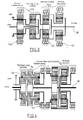
- a 4-shaft two-gear epicyclic gear 10a can be seen with two individual shafts and two coupling shafts, wherein the first coupling shaft 30 is formed by the web shafts of one and the sun gear of the other planetary gear 36.
- the second coupling shaft 32 is formed by the ring gear shaft of the one 34 and the land shaft of the other planetary gear 36.
- the epicyclic gear is a superposition gear, and the brake 14a is coupled to the ring gear of the second planetary gear 36.
- the reversing gear 12a is a 3-shaft epicyclic gearbox, wherein the first shaft is connected to the output shaft of the 4-shaft epicyclic gear 10a and a second shaft is coupled to at least one driven wheel of the industrial truck.
- the output shaft is designated 38.
- a third shaft of the reversing gear 12a is provided with a brake 40 and thus can be fixed.
- Two shafts of the reversing gear 12a are connected to each other by means of a coupling 42. In the case shown, it is the shafts 38 and connected to the ring gear of the epicyclic shaft.
- a 4-shaft two-gear epicyclic gear 10b can be seen and the reversing gear 12b as a 4-shaft epicyclic gear.
- the first coupling shaft of the epicyclic gear 10b is formed by the land shaft of the one and the sun gear of the other planetary gear and the second coupling shaft is formed by the sun gear of the one and the land of the other planetary gear.
- a brake 40 is associated with a coupling shaft, the other coupling shaft is connected to the output 38.
- the epicyclic gear 10c is a 4-shaft single-speed epicyclic gear and the reverse gear 12c is a 4-shaft epicyclic gear 10e.
- the web of the epicyclic gear 10c is provided with three-stage stepped planetary gears 44, each stage of the planets respectively being engaged with a sun gear or a ring gear.
- the web and the three meshing with the planetary gears 44 are each connected to a connecting shaft.
- the brake 14c is connected to the sun gear coupled to the last stage of the stepped planetary gears 44.
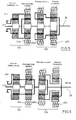
- Fig. 5 shows a 4-shaft two-gear epicyclic gear 10d and a reversing gear 12d as a 4-shaft epicyclic gear.
- a first coupling shaft is formed by the ring gear of the two planetary gear.
- a second coupling shaft is formed by the sun gear of the one and the ridge of the other planetary gear.
- the epicyclic gear 10e is a 4-shaft two-gear planetary gear and the reverse gear 12e is a 4-shaft epicyclic gear.
- the first coupling shaft of the planetary gear 10e is formed by the ridge waves of the two planetary gear and the second coupling shaft by the sun gear of the two planetary gear.
- the reverse gear 12f is a 4-shaft single-speed epicyclic gear having two-stage stage planets 50, with a sun gear and a ring gear meshing with the planet of one stage and a sun gear or ring gear with the other stage planet.
- the web and the three gears meshing with the planets 50 are each connected to a connecting shaft.
- the reverse gear 12f is a Vorlegegetriebe, wherein the input shaft of the reversing gear 12f is connected to the output shaft of the epicyclic gear 10f and the output shaft of the reversing gear 12f is coupled to at least one driven wheel (not shown here) of the truck.
- the direction of rotation of the output shaft 38 depends on which of the two clutches 52, 54 is actuated.
- the gear stage of the reversing gear consists of three meshing gears and the other gear of two meshing gears, so that depending on the clutch operation one or the other direction of rotation results.
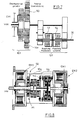
- a transmission housing 56 is shown in which first and second electric motors EM1 and EM2 are arranged coaxially and at an axial distance from one another.
- the second electric motor EM2 is arranged concentrically around the output shaft of the reversing gear 12g.
- the summing gear (see Fig. 1) is replaced by a direct flanging of the electric motor EM2 to the output shaft of the reversing gear 12g.
- the 4-shaft epicyclic gear is a 4-shaft single-speed epicyclic gearbox as shown in FIG.
- the reversing gear 12g is a 4-shaft epicyclic gearbox.
- a concentrically arranged hydraulic pump P1 is driven directly by the hollow shaft of the first electric motor EM1.
- FIG. 9 shows an alternative to the arrangement according to FIG. 8, in which the electric motors EM1 and EM2 are arranged with their shafts parallel and at a distance from one another.
- the epicyclic gear 10h and the reversing gear 12h are similar to those of the drive system shown in FIG. 8.
- a second hydraulic pump P2 is driven by the shaft of the second electric motor EM2 through respective gears or through the output shaft of the reverse gear 12h.
Landscapes
- Engineering & Computer Science (AREA)
- Transportation (AREA)
- Mechanical Engineering (AREA)
- Chemical & Material Sciences (AREA)
- Combustion & Propulsion (AREA)
- Power Engineering (AREA)
- Life Sciences & Earth Sciences (AREA)
- Structural Engineering (AREA)
- General Engineering & Computer Science (AREA)
- Automation & Control Theory (AREA)
- Civil Engineering (AREA)
- Geology (AREA)
- Sustainable Development (AREA)
- Sustainable Energy (AREA)
- Electric Propulsion And Braking For Vehicles (AREA)
- Hybrid Electric Vehicles (AREA)
- Arrangement Of Transmissions (AREA)
- Control Of Vehicle Engines Or Engines For Specific Uses (AREA)
Applications Claiming Priority (1)
| Application Number | Priority Date | Filing Date | Title |
|---|---|---|---|
| DE102006030945A DE102006030945A1 (de) | 2006-07-05 | 2006-07-05 | Antriebssystem für ein Flurförderzeug mit einer Brennkraftmaschine |
Publications (3)
| Publication Number | Publication Date |
|---|---|
| EP1876080A2 true EP1876080A2 (fr) | 2008-01-09 |
| EP1876080A3 EP1876080A3 (fr) | 2011-03-30 |
| EP1876080B1 EP1876080B1 (fr) | 2012-12-12 |
Family
ID=38621041
Family Applications (1)
| Application Number | Title | Priority Date | Filing Date |
|---|---|---|---|
| EP07012652A Not-in-force EP1876080B1 (fr) | 2006-07-05 | 2007-06-28 | Système d'entraînement pour un chariot de manutention doté d'un moteur à combustion interne |
Country Status (4)
| Country | Link |
|---|---|
| US (1) | US8133150B2 (fr) |
| EP (1) | EP1876080B1 (fr) |
| CN (1) | CN101100189A (fr) |
| DE (1) | DE102006030945A1 (fr) |
Cited By (3)
| Publication number | Priority date | Publication date | Assignee | Title |
|---|---|---|---|---|
| WO2012079608A1 (fr) * | 2010-12-17 | 2012-06-21 | Volvo Lastvagnar Ab | Procédé pour commander une chaîne cinématique d'un véhicule |
| FR3015452A1 (fr) * | 2013-12-20 | 2015-06-26 | Manitou Bf | Chariot de manutention |
| WO2018169463A1 (fr) * | 2017-03-13 | 2018-09-20 | BAE Systems Hägglunds Aktiebolag | Pignon surmultiplicateur mécanique et inverse combiné pour groupe motopropulseur hybride à dérivation de puissance |
Families Citing this family (20)
| Publication number | Priority date | Publication date | Assignee | Title |
|---|---|---|---|---|
| US8373375B2 (en) | 2010-10-01 | 2013-02-12 | Deere & Company | Electro-mechanical drive with extended constant power speed range |
| JP5783786B2 (ja) * | 2011-04-28 | 2015-09-24 | ニチユ三菱フォークリフト株式会社 | ハイブリッド型産業車両 |
| JP5776892B2 (ja) * | 2011-07-13 | 2015-09-09 | スズキ株式会社 | ハイブリッド駆動装置 |
| CN102910081B (zh) * | 2011-08-05 | 2014-12-03 | 光阳工业股份有限公司 | 车辆的发电系统及其发电方法 |
| DE102011085496A1 (de) * | 2011-10-31 | 2013-05-02 | Deere & Company | Lastschaltgetriebe |
| CN102943859B (zh) * | 2012-11-23 | 2015-07-08 | 天津工程机械研究院 | 一种装载机用液压机械无级变速器 |
| US9145133B2 (en) * | 2013-11-08 | 2015-09-29 | Ford Global Technologies, Llc | Method and system for selecting an engine operating point for a hybrid vehicle |
| CN103738154B (zh) * | 2014-01-07 | 2016-02-10 | 天津工程机械研究院 | 油电液复合四驱混合动力系统及控制方法 |
| US9689319B2 (en) * | 2014-09-12 | 2017-06-27 | Caterpillar Inc. | Power system having efficiency-based speed control |
| DE102015215074B4 (de) | 2015-08-06 | 2023-08-24 | Zf Friedrichshafen Ag | Getriebesystem für einen Hybridantrieb eines Kraftfahrzeugs |
| DE102015215070B4 (de) | 2015-08-06 | 2023-08-03 | Zf Friedrichshafen Ag | Getriebesystem für einen Hybridantrieb eines Kraftfahrzeugs |
| EP3350485B1 (fr) * | 2015-09-16 | 2020-07-22 | Volvo Truck Corporation | Groupe motopropulseur de véhicule et procédé de passage à un rapport supérieur d'engrenage |
| DE102015118535A1 (de) * | 2015-10-29 | 2017-05-04 | Terex MHPS IP Management GmbH | Schwerlaststapler |
| CN105446391A (zh) * | 2015-12-07 | 2016-03-30 | 长安大学 | 一种货车长下坡行驶制动器温升预测方法 |
| CN109073048A (zh) * | 2015-12-29 | 2018-12-21 | 桑迪普·拉莫斯·帕拉斯帕加 | 一种行星齿轮箱 |
| DE102016102575A1 (de) | 2016-02-15 | 2017-08-17 | Dr. Ing. H.C. F. Porsche Aktiengesellschaft | Antriebsanordnung |
| CN106314125A (zh) * | 2016-08-19 | 2017-01-11 | 福建农林大学 | 一种用于增程式电动车的动力合成机构 |
| IT201800007329A1 (it) * | 2018-07-19 | 2020-01-19 | Sistema di propulsione ibrido endotermico/elettrico per un veicolo | |
| CN111392049B (zh) * | 2020-02-24 | 2022-02-25 | 北京中航智科技有限公司 | 一种共轴反桨直升机传动系统 |
| US11491868B2 (en) * | 2021-03-10 | 2022-11-08 | Arvinmeritor Technology, Llc | Axle assembly having a gear reduction module with multiple gear sets |
Citations (3)
| Publication number | Priority date | Publication date | Assignee | Title |
|---|---|---|---|---|
| US3566717A (en) | 1969-03-17 | 1971-03-02 | Trw Inc | Power train using multiple power sources |
| DE10141923A1 (de) | 2000-08-29 | 2002-03-28 | Toyota Motor Co Ltd | Leistungsabgabegerät, Motorfahrzeug einschließlich des Leistungsabgabegeräts und ihre Steuerverfahren |
| DE10340472A1 (de) | 2003-09-03 | 2005-06-09 | Jungheinrich Ag | Antriebssystem für ein Flurförderzeug und Verfahren zum Betrieb des Antriebssystems |
Family Cites Families (7)
| Publication number | Priority date | Publication date | Assignee | Title |
|---|---|---|---|---|
| US5558589A (en) * | 1995-07-20 | 1996-09-24 | General Motors Corporation | Two-mode, compound-split, electro-mechanical vehicular transmission |
| US5931757A (en) * | 1998-06-24 | 1999-08-03 | General Motors Corporation | Two-mode, compound-split electro-mechanical vehicular transmission |
| JP3926514B2 (ja) * | 1999-08-17 | 2007-06-06 | 本田技研工業株式会社 | ハイブリッド車両の制御装置 |
| DE19955311C2 (de) * | 1999-11-17 | 2003-12-24 | Jungheinrich Ag | Antriebssystem für ein Flurförderzeug |
| DE10130032A1 (de) * | 2000-09-01 | 2003-01-23 | Peter Tenberge | Automatikgetriebe für Fahrzeuge |
| JP4203828B2 (ja) * | 2006-07-10 | 2009-01-07 | アイシン・エィ・ダブリュ株式会社 | ハイブリッド駆動装置 |
| US7648440B2 (en) * | 2007-01-24 | 2010-01-19 | Gm Global Technology Operations, Inc. | Method and apparatus to control operation of an electro-mechanical transmission |
-
2006
- 2006-07-05 DE DE102006030945A patent/DE102006030945A1/de not_active Withdrawn
-
2007
- 2007-06-28 EP EP07012652A patent/EP1876080B1/fr not_active Not-in-force
- 2007-07-03 US US11/772,913 patent/US8133150B2/en not_active Expired - Fee Related
- 2007-07-05 CN CNA200710127455XA patent/CN101100189A/zh active Pending
Patent Citations (3)
| Publication number | Priority date | Publication date | Assignee | Title |
|---|---|---|---|---|
| US3566717A (en) | 1969-03-17 | 1971-03-02 | Trw Inc | Power train using multiple power sources |
| DE10141923A1 (de) | 2000-08-29 | 2002-03-28 | Toyota Motor Co Ltd | Leistungsabgabegerät, Motorfahrzeug einschließlich des Leistungsabgabegeräts und ihre Steuerverfahren |
| DE10340472A1 (de) | 2003-09-03 | 2005-06-09 | Jungheinrich Ag | Antriebssystem für ein Flurförderzeug und Verfahren zum Betrieb des Antriebssystems |
Cited By (4)
| Publication number | Priority date | Publication date | Assignee | Title |
|---|---|---|---|---|
| WO2012079608A1 (fr) * | 2010-12-17 | 2012-06-21 | Volvo Lastvagnar Ab | Procédé pour commander une chaîne cinématique d'un véhicule |
| US9096215B2 (en) | 2010-12-17 | 2015-08-04 | Volvo Lastvagnar Ab | Method to control a drivetrain of a vehicle |
| FR3015452A1 (fr) * | 2013-12-20 | 2015-06-26 | Manitou Bf | Chariot de manutention |
| WO2018169463A1 (fr) * | 2017-03-13 | 2018-09-20 | BAE Systems Hägglunds Aktiebolag | Pignon surmultiplicateur mécanique et inverse combiné pour groupe motopropulseur hybride à dérivation de puissance |
Also Published As
| Publication number | Publication date |
|---|---|
| US20080041653A1 (en) | 2008-02-21 |
| US8133150B2 (en) | 2012-03-13 |
| EP1876080B1 (fr) | 2012-12-12 |
| CN101100189A (zh) | 2008-01-09 |
| DE102006030945A1 (de) | 2008-02-14 |
| EP1876080A3 (fr) | 2011-03-30 |
Similar Documents
| Publication | Publication Date | Title |
|---|---|---|
| EP1876080B1 (fr) | Système d'entraînement pour un chariot de manutention doté d'un moteur à combustion interne | |
| DE19955311C2 (de) | Antriebssystem für ein Flurförderzeug | |
| EP1954542B1 (fr) | Systeme hybride de propulsion, et procede pour commander une boite de vitesses pour un systeme hybride de propulsion | |
| DE10340472B4 (de) | Antriebssystem für ein Flurförderzeug | |
| EP3661787B1 (fr) | Boîte de vitesses pour un système de propulsion hybride, système de propulsion hybride et véhicule | |
| EP2855226A2 (fr) | Procédé et dispositif de commande d'une machine de travail mobile | |
| DE102013224383A1 (de) | Leistungsverzweigter Achsantrieb für Arbeitsmaschinen | |
| DE19909424A1 (de) | Hybridgetriebe für Fahrzeuge | |
| DE102008022797A1 (de) | Hybridantriebsstrang mit einer Maschineneingangskupplung und Steuerverfahren | |
| DE102013206176A1 (de) | Fahrzeugantrieb | |
| DE102004028620B4 (de) | Antriebssystem für eine mobile Arbeitsmaschine mit angetriebenen Rädern, insbesondere ein Flurförderzeug | |
| EP2062770A1 (fr) | Système d'entraînement pour véhicules automobiles | |
| DE102020213675A1 (de) | Leistungssteuerung mit getriebe mit transienter boostfunktion | |
| AT522931A1 (de) | Elektrisch angetriebene achsanordnung für ein fahrzeug | |
| DE19955312A1 (de) | Antriebssystem für Flurförderzeuge | |
| DE102019214412B4 (de) | Verfahren zum Betreiben eines Antriebsstrangs für eine Arbeitsmaschine, Antriebsstrang für eine Arbeitsmaschine und Arbeitsmaschine | |
| DE102020101667A1 (de) | Antriebsstrang für ein Kraftfahrzeug | |
| DE19955313A1 (de) | Antriebssystem für Flurförderzeuge | |
| EP4215393B1 (fr) | Entraînement d'essieu à répartition de puissance et véhicule agricole | |
| DE102010020592B4 (de) | Verfahren zum Regeln einer Pumpe für ein Hybridgetriebe | |
| DE102022210721A1 (de) | System und verfahren zur traktionssteuerung in einem arbeitsfahrzeug mit einem stufenlosen e-getriebe | |
| DE102017213373A1 (de) | Getriebe für eine Hybridantriebsanordnung | |
| DE102019203735A1 (de) | Antriebsstrang für eine Arbeitsmaschine und Arbeitsmaschine | |
| EP3661788B1 (fr) | Boîte de vitesses pour un système de propulsion hybride, système de propulsion hybride et véhicule | |
| EP0304919A2 (fr) | Engrenage planétaire à réglage continu |
Legal Events
| Date | Code | Title | Description |
|---|---|---|---|
| PUAI | Public reference made under article 153(3) epc to a published international application that has entered the european phase |
Free format text: ORIGINAL CODE: 0009012 |
|
| AK | Designated contracting states |
Kind code of ref document: A2 Designated state(s): AT BE BG CH CY CZ DE DK EE ES FI FR GB GR HU IE IS IT LI LT LU LV MC MT NL PL PT RO SE SI SK TR |
|
| AX | Request for extension of the european patent |
Extension state: AL BA HR MK YU |
|
| PUAL | Search report despatched |
Free format text: ORIGINAL CODE: 0009013 |
|
| AK | Designated contracting states |
Kind code of ref document: A3 Designated state(s): AT BE BG CH CY CZ DE DK EE ES FI FR GB GR HU IE IS IT LI LT LU LV MC MT NL PL PT RO SE SI SK TR |
|
| AX | Request for extension of the european patent |
Extension state: AL BA HR MK RS |
|
| 17P | Request for examination filed |
Effective date: 20110921 |
|
| 17Q | First examination report despatched |
Effective date: 20111104 |
|
| AKX | Designation fees paid |
Designated state(s): DE FR IT |
|
| GRAP | Despatch of communication of intention to grant a patent |
Free format text: ORIGINAL CODE: EPIDOSNIGR1 |
|
| RIC1 | Information provided on ipc code assigned before grant |
Ipc: B60W 10/06 20060101ALN20120705BHEP Ipc: B60W 20/00 20060101AFI20120705BHEP Ipc: B60K 6/445 20071001ALI20120705BHEP |
|
| GRAS | Grant fee paid |
Free format text: ORIGINAL CODE: EPIDOSNIGR3 |
|
| GRAC | Information related to communication of intention to grant a patent modified |
Free format text: ORIGINAL CODE: EPIDOSCIGR1 |
|
| RIC1 | Information provided on ipc code assigned before grant |
Ipc: B60W 20/00 20060101AFI20120927BHEP Ipc: B60K 6/445 20071001ALI20120927BHEP Ipc: B60W 10/06 20060101ALN20120927BHEP |
|
| GRAA | (expected) grant |
Free format text: ORIGINAL CODE: 0009210 |
|
| AK | Designated contracting states |
Kind code of ref document: B1 Designated state(s): DE FR IT |
|
| REG | Reference to a national code |
Ref country code: DE Ref legal event code: R096 Ref document number: 502007011015 Country of ref document: DE Effective date: 20130207 |
|
| PLBE | No opposition filed within time limit |
Free format text: ORIGINAL CODE: 0009261 |
|
| STAA | Information on the status of an ep patent application or granted ep patent |
Free format text: STATUS: NO OPPOSITION FILED WITHIN TIME LIMIT |
|
| 26N | No opposition filed |
Effective date: 20130913 |
|
| REG | Reference to a national code |
Ref country code: DE Ref legal event code: R097 Ref document number: 502007011015 Country of ref document: DE Effective date: 20130913 |
|
| REG | Reference to a national code |
Ref country code: FR Ref legal event code: PLFP Year of fee payment: 10 |
|
| PGFP | Annual fee paid to national office [announced via postgrant information from national office to epo] |
Ref country code: FR Payment date: 20160630 Year of fee payment: 10 |
|
| PGFP | Annual fee paid to national office [announced via postgrant information from national office to epo] |
Ref country code: IT Payment date: 20160624 Year of fee payment: 10 |
|
| PGFP | Annual fee paid to national office [announced via postgrant information from national office to epo] |
Ref country code: DE Payment date: 20170831 Year of fee payment: 11 |
|
| REG | Reference to a national code |
Ref country code: FR Ref legal event code: ST Effective date: 20180228 |
|
| PG25 | Lapsed in a contracting state [announced via postgrant information from national office to epo] |
Ref country code: IT Free format text: LAPSE BECAUSE OF NON-PAYMENT OF DUE FEES Effective date: 20170628 Ref country code: FR Free format text: LAPSE BECAUSE OF NON-PAYMENT OF DUE FEES Effective date: 20170630 |
|
| REG | Reference to a national code |
Ref country code: DE Ref legal event code: R119 Ref document number: 502007011015 Country of ref document: DE |
|
| PG25 | Lapsed in a contracting state [announced via postgrant information from national office to epo] |
Ref country code: DE Free format text: LAPSE BECAUSE OF NON-PAYMENT OF DUE FEES Effective date: 20190101 |