EP1876329A2 - Galet de came à levier d'une commande de soupape d'un moteur à combustion interne - Google Patents
Galet de came à levier d'une commande de soupape d'un moteur à combustion interne Download PDFInfo
- Publication number
- EP1876329A2 EP1876329A2 EP07111405A EP07111405A EP1876329A2 EP 1876329 A2 EP1876329 A2 EP 1876329A2 EP 07111405 A EP07111405 A EP 07111405A EP 07111405 A EP07111405 A EP 07111405A EP 1876329 A2 EP1876329 A2 EP 1876329A2
- Authority
- EP
- European Patent Office
- Prior art keywords
- lever body
- lever
- cam follower
- contact surface
- center plane
- Prior art date
- Legal status (The legal status is an assumption and is not a legal conclusion. Google has not performed a legal analysis and makes no representation as to the accuracy of the status listed.)
- Granted
Links
- 238000002485 combustion reaction Methods 0.000 title claims description 8
- 239000000463 material Substances 0.000 claims description 4
- 230000000284 resting effect Effects 0.000 claims description 3
- 238000000034 method Methods 0.000 claims 1
- 238000004519 manufacturing process Methods 0.000 description 4
- 230000005540 biological transmission Effects 0.000 description 3
- 230000000875 corresponding effect Effects 0.000 description 2
- 230000000694 effects Effects 0.000 description 2
- 239000002245 particle Substances 0.000 description 2
- 238000005096 rolling process Methods 0.000 description 2
- 230000001133 acceleration Effects 0.000 description 1
- 239000011248 coating agent Substances 0.000 description 1
- 238000000576 coating method Methods 0.000 description 1
- 230000001276 controlling effect Effects 0.000 description 1
- 230000002596 correlated effect Effects 0.000 description 1
- 230000002542 deteriorative effect Effects 0.000 description 1
- 238000006073 displacement reaction Methods 0.000 description 1
- 238000002347 injection Methods 0.000 description 1
- 239000007924 injection Substances 0.000 description 1
- 239000010687 lubricating oil Substances 0.000 description 1
- 230000007935 neutral effect Effects 0.000 description 1
- 238000002360 preparation method Methods 0.000 description 1
- 230000002441 reversible effect Effects 0.000 description 1
Images

Classifications
-
- F—MECHANICAL ENGINEERING; LIGHTING; HEATING; WEAPONS; BLASTING
- F01—MACHINES OR ENGINES IN GENERAL; ENGINE PLANTS IN GENERAL; STEAM ENGINES
- F01L—CYCLICALLY OPERATING VALVES FOR MACHINES OR ENGINES
- F01L1/00—Valve-gear or valve arrangements, e.g. lift-valve gear
- F01L1/12—Transmitting gear between valve drive and valve
- F01L1/18—Rocking arms or levers
- F01L1/185—Overhead end-pivot rocking arms
-
- F—MECHANICAL ENGINEERING; LIGHTING; HEATING; WEAPONS; BLASTING
- F01—MACHINES OR ENGINES IN GENERAL; ENGINE PLANTS IN GENERAL; STEAM ENGINES
- F01L—CYCLICALLY OPERATING VALVES FOR MACHINES OR ENGINES
- F01L1/00—Valve-gear or valve arrangements, e.g. lift-valve gear
- F01L1/12—Transmitting gear between valve drive and valve
- F01L1/18—Rocking arms or levers
- F01L1/181—Centre pivot rocking arms
-
- F—MECHANICAL ENGINEERING; LIGHTING; HEATING; WEAPONS; BLASTING
- F01—MACHINES OR ENGINES IN GENERAL; ENGINE PLANTS IN GENERAL; STEAM ENGINES
- F01L—CYCLICALLY OPERATING VALVES FOR MACHINES OR ENGINES
- F01L1/00—Valve-gear or valve arrangements, e.g. lift-valve gear
- F01L1/12—Transmitting gear between valve drive and valve
- F01L1/14—Tappets; Push rods
- F01L1/16—Silencing impact; Reducing wear
-
- F—MECHANICAL ENGINEERING; LIGHTING; HEATING; WEAPONS; BLASTING
- F01—MACHINES OR ENGINES IN GENERAL; ENGINE PLANTS IN GENERAL; STEAM ENGINES
- F01L—CYCLICALLY OPERATING VALVES FOR MACHINES OR ENGINES
- F01L1/00—Valve-gear or valve arrangements, e.g. lift-valve gear
- F01L1/12—Transmitting gear between valve drive and valve
- F01L1/18—Rocking arms or levers
- F01L2001/188—Fulcrums at upper surface
-
- F—MECHANICAL ENGINEERING; LIGHTING; HEATING; WEAPONS; BLASTING
- F01—MACHINES OR ENGINES IN GENERAL; ENGINE PLANTS IN GENERAL; STEAM ENGINES
- F01L—CYCLICALLY OPERATING VALVES FOR MACHINES OR ENGINES
- F01L2301/00—Using particular materials
-
- F—MECHANICAL ENGINEERING; LIGHTING; HEATING; WEAPONS; BLASTING
- F01—MACHINES OR ENGINES IN GENERAL; ENGINE PLANTS IN GENERAL; STEAM ENGINES
- F01L—CYCLICALLY OPERATING VALVES FOR MACHINES OR ENGINES
- F01L2303/00—Manufacturing of components used in valve arrangements
-
- F—MECHANICAL ENGINEERING; LIGHTING; HEATING; WEAPONS; BLASTING
- F01—MACHINES OR ENGINES IN GENERAL; ENGINE PLANTS IN GENERAL; STEAM ENGINES
- F01L—CYCLICALLY OPERATING VALVES FOR MACHINES OR ENGINES
- F01L2305/00—Valve arrangements comprising rollers
Definitions
- the invention relates to a lever-like cam follower of a valve train of an internal combustion engine for actuating a charge cycle controlling Tellerhubventils, with an elongated lever body, on both sides whose longitudinal center plane extends a contact surface for the shaft end surface of the Tellerhubventils and with a dome-shaped recess on a resting in the engine pivot bearings is supported ball joint, as well as with a longitudinal center plane of the lever body angle-aligning tap surface for a cam of a camshaft or for an actuating surface having the same effect.
- cam followers are known to be used for stroke transmission in valve trains with indirect drive and are known in the prior art in a variety of kinematic, manufacturing engineering and mechanical designs. Due to their pivotal movement, these cam followers are common, the contact surface extending in each case on the lever body carries out a sliding movement superimposed by a rolling movement on the shaft end face of the plate lifting valve. The required angular alignment of the contact surface with respect to the shaft end surface takes place mainly via a line contact between the cam and the associated Abgriffs Type otherwise ball-jointed on the pivot bearing cam follower.
- the actuating surface which acts in the same way as the cam can also be the stroke transmission surface of a cam-driven intermediate lever, as used in fully variable valve trains for low-throttle load control in internal combustion engines of the automobile manufacturer BMW.
- the wear protection measures primarily include a surface coating of one or both contact partners with wear-resistant materials. However, the workpiece preparation and the subsequent application of such layers is associated with a significantly increased manufacturing and cost overhead.
- the present invention is therefore the object of a lever-like cam follower of the type mentioned in such a way that the contact conditions between the contact surface of the lever body and the shaft end surface of the Tellerhubventils improved in favor of increased wear resistance of these contact partners or favor higher allowable contact forces with constant wear resistance with simple means become, so that the manufacturing effort of the cam follower and the costs incurred remain largely unchanged.
- the increased wear resistance of the mentioned contact partners is then based on the fact that, on the one hand, constantly changing sections of the shaft end face are involved in the transmission of the valve actuating forces, and consequently a significantly more uniform stress on the shaft end surface can be achieved.
- the rotation of the Tellerhubventils leads to a decrease in the Gleitanteils while increasing the Wälzanteils the contact surface, whereby the risk of surface wear is significantly reduced by abrasive particles.
- the eccentric contacting of the shaft end surface can be generated by selecting one of the feature combinations of the cam follower targeted and at the same time low effort and largely cost neutral compared to conventional cam followers.
- a conventional cylindrical or cylindrical-end profiled roller is provided, but the roller bearing the roller is not aligned at right angles, but inclined to the longitudinal center plane of the lever body. Corresponding to the aforementioned half cone angle of the roller, this angle of inclination also leads to an inclination of the longitudinal center plane of the lever body and consequently to the explained eccentric displacement of the contact point on the shaft end surface.
- the shaft end surface is contacted eccentrically by the longitudinal plane of symmetry of the contact surface per se being inclined relative to the longitudinal center plane of the lever body.
- a cylindrical or cylindrical-end profiled roller in a conventional, ie in orthogonal to the longitudinal center plane alignment as low-friction Abgriffs simulation for the cam or for the same effect actuating surface can also be provided here.
- the cam follower may also be equipped with a weight-reducing rigid sliding surface as a tap area.
- the contact surface should be formed convexly curved both in the longitudinal direction of the lever body and orthogonal to the longitudinal direction.
- Such a shaped contact surface provides, in particular in conjunction with a flat shaft end surface for a defined pressure zone, so that the occurrence of wear-promoting edge support is effectively excluded.
- lever body to be made in favor of low production costs in a chipless forming of sheet material.
- cam follower may be formed as a drag lever, wherein the dome-shaped recess and the contact surface are arranged opposite to the end portions of the lever body and the Abgriffs spectrum in a central portion of the lever body.
- the cam follower may also be designed as a centrally mounted rocker arm, wherein the tap area and the contact surface are arranged opposite one another at the end sections of the lever body and the dome-shaped recess in a middle section of the lever body.
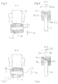
- FIG. 1 discloses a valve drive 1 of an internal combustion engine 2 in assembly with a lever-type cam follower 4 embodied as a drag lever 3.
- the drag lever 3 comprises a generally denoted by 5, elongated lever body with the variants explained below 5a to 5c, which is made in a chipless forming of sheet material, and a roller 6 which is arranged needle-mounted on a lever body 5 rigidly mounted pin 7 and serves as a low-friction tap surface 8 for a cam 9 of a camshaft 10.
- a dome-shaped recess 13 for ball-joint support of the finger lever 3 on a resting in the engine 2 pivot bearing 14 and a generally 15 and according to their variants also explained below with 15 a to 15c designated contact surface for the shaft end surface 16 of a cam lever 17 actuated by the cam follower lever 17.
- convex and circular arc curved contact surface 15 performs a superimposed by a rolling sliding on the shaft end face 16 of the Tellerhubventils 17.
- a reduction of the wear of these contact partners 15 and 16 reducing rotation of the Tellerhubventils 17 about its longitudinal axis is specifically stimulated by the fact that the roller 6 is formed as a truncated cone-shaped roller 6a of Figure 3 and having designated 18, half cone angle. This is exaggerated here for better illustration and assumes in practice, for example, a value of about 1 °. Also in the event that the roller 6a has end-side end profiles, the angular alignment of the longitudinal center plane 19 of the lever body 5a is effected by line contact of the roller 6a on the cam 9.
- the section BB shown in FIG. 6 relates to the feature combination c) explained at the outset, according to which the contact surface 15c for the shaft end surface 16 of the plate-lifting valve 17 has a relation to the longitudinal center plane 19 of the lever body 5c inclined longitudinal symmetry plane 22.
- Their angle of inclination designated by 23 is in turn greatly exaggerated and, in conjunction with the orthogonal to the longitudinal direction of the lever body 5c convex and here also arcuate curved contact surface 15c to the marked by the arrow eccentric contacting the shank end surface 16th
- the invention is of course not limited to the single-acting lever according to the embodiments shown in Figures 1 and 2, but can also be used in the initially mentioned fully variable valve trains as well as partially variable valve trains with reversible levers become.
- switchable levers are composed of a plurality of individual levers which can be coupled by means of a locking mechanism, one of these individual levers being supported on the pivot bearing in ball-joint fashion and having one of the described combinations of features.
Landscapes
- Engineering & Computer Science (AREA)
- Mechanical Engineering (AREA)
- General Engineering & Computer Science (AREA)
- Valve-Gear Or Valve Arrangements (AREA)
- Mechanically-Actuated Valves (AREA)
Applications Claiming Priority (1)
| Application Number | Priority Date | Filing Date | Title |
|---|---|---|---|
| DE102006031031A DE102006031031A1 (de) | 2006-07-05 | 2006-07-05 | Hebelartiger Nockenfolger eines Ventiltriebs einer Brennkraftmaschine |
Publications (3)
| Publication Number | Publication Date |
|---|---|
| EP1876329A2 true EP1876329A2 (fr) | 2008-01-09 |
| EP1876329A3 EP1876329A3 (fr) | 2010-04-07 |
| EP1876329B1 EP1876329B1 (fr) | 2013-08-14 |
Family
ID=38596164
Family Applications (1)
| Application Number | Title | Priority Date | Filing Date |
|---|---|---|---|
| EP07111405.2A Not-in-force EP1876329B1 (fr) | 2006-07-05 | 2007-06-29 | Galet de came à levier d'une commande de soupape d'un moteur à combustion interne |
Country Status (2)
| Country | Link |
|---|---|
| EP (1) | EP1876329B1 (fr) |
| DE (1) | DE102006031031A1 (fr) |
Cited By (1)
| Publication number | Priority date | Publication date | Assignee | Title |
|---|---|---|---|---|
| US11156284B2 (en) | 2017-07-20 | 2021-10-26 | Aktiebolaget Skf | Self-aligning cam follower roller device |
Families Citing this family (1)
| Publication number | Priority date | Publication date | Assignee | Title |
|---|---|---|---|---|
| DE102013102150A1 (de) * | 2013-03-05 | 2014-09-25 | Dr. Ing. H.C. F. Porsche Aktiengesellschaft | Schlepphebelanordnung |
Citations (2)
| Publication number | Priority date | Publication date | Assignee | Title |
|---|---|---|---|---|
| JPH09280016A (ja) | 1996-04-12 | 1997-10-28 | Kubota Corp | 頭上弁エンジンの動弁装置 |
| WO2000020730A1 (fr) | 1998-10-05 | 2000-04-13 | Eaton Automotive S.P.A. | Ensemble commande des soupapes |
Family Cites Families (16)
| Publication number | Priority date | Publication date | Assignee | Title |
|---|---|---|---|---|
| CH220829A (de) * | 1940-11-23 | 1942-04-30 | Porsche Kg | Vorrichtung zum selbsttätigen Verdrehen mittelbar betätigter Ventile ventilgesteuerter Brennkraftmaschinen gegenüber ihrem Sitz. |
| US2572106A (en) * | 1949-12-01 | 1951-10-23 | Gen Motors Corp | Valve rotating device |
| DE903151C (de) * | 1950-05-11 | 1954-02-01 | Fiat Spa | Brennkraftmaschine mit Tellerventilen |
| FR1030167A (fr) * | 1950-12-27 | 1953-06-10 | Perfectionnements à la commande des soupapes pour moteurs à combustion interne | |
| FR1052163A (fr) * | 1951-03-23 | 1954-01-21 | Fiat Spa | Dispositif pour produire la rotation des soupapes dans les moteurs à soupapes en tête |
| FR62166E (fr) * | 1951-11-23 | 1955-06-10 | Perfectionnements à la commande des soupapes pour moteurs à combustion interne | |
| DE931076C (de) * | 1953-05-16 | 1955-08-01 | Volkswagenwerk G M B H | Zwangsweise arbeitende Ventildreheinrichtung, insbesondere fuer Brennkraftmaschinen |
| DE959422C (de) * | 1955-05-12 | 1957-03-07 | Maschf Augsburg Nuernberg Ag | Drehbares Ventil fuer Brennkraftmaschinen |
| AT272762B (de) * | 1966-01-26 | 1969-07-25 | Ustav Pro Vyzkum Motorovych Vo | Ventildrehvorrichtung für Brennkraftmaschinen |
| DE2044727A1 (de) * | 1970-09-10 | 1972-03-16 | Prelle, Erich, 3011 Egestorf | Vorrichtung zum Drehen eines axial bewegbaren Bauteiles, insbesondere eines Ventils für Verbrennungskraftmaschinen |
| FR2573478B1 (fr) * | 1984-11-19 | 1987-02-06 | Peugeot | Dispositif a un seul culbuteur, pour l'actionnement de deux soupapes |
| DE9116143U1 (de) * | 1991-04-22 | 1992-03-19 | Steyr-Daimler-Puch Ag, Wien | Ventilhebel für Brennkraftmaschinen |
| DE19644916A1 (de) * | 1996-10-29 | 1998-04-30 | Schaeffler Waelzlager Ohg | Ventiltrieb |
| JP2001152817A (ja) * | 1999-12-01 | 2001-06-05 | Teikoku Piston Ring Co Ltd | ロッカアーム及び内燃機関の動弁機構 |
| JP2002276309A (ja) * | 2001-03-22 | 2002-09-25 | Nsk Ltd | ロッカーアーム |
| JP2004225551A (ja) * | 2003-01-20 | 2004-08-12 | Koyo Seiko Co Ltd | カムフォロア |
-
2006
- 2006-07-05 DE DE102006031031A patent/DE102006031031A1/de not_active Ceased
-
2007
- 2007-06-29 EP EP07111405.2A patent/EP1876329B1/fr not_active Not-in-force
Patent Citations (2)
| Publication number | Priority date | Publication date | Assignee | Title |
|---|---|---|---|---|
| JPH09280016A (ja) | 1996-04-12 | 1997-10-28 | Kubota Corp | 頭上弁エンジンの動弁装置 |
| WO2000020730A1 (fr) | 1998-10-05 | 2000-04-13 | Eaton Automotive S.P.A. | Ensemble commande des soupapes |
Cited By (1)
| Publication number | Priority date | Publication date | Assignee | Title |
|---|---|---|---|---|
| US11156284B2 (en) | 2017-07-20 | 2021-10-26 | Aktiebolaget Skf | Self-aligning cam follower roller device |
Also Published As
| Publication number | Publication date |
|---|---|
| DE102006031031A1 (de) | 2008-01-10 |
| EP1876329B1 (fr) | 2013-08-14 |
| EP1876329A3 (fr) | 2010-04-07 |
Similar Documents
| Publication | Publication Date | Title |
|---|---|---|
| EP3170997B1 (fr) | Commande de soupape variable comprenant un culbuteur | |
| AT505832B1 (de) | Motorbremseinrichtung für eine brennkraftmaschine | |
| DE10257705A1 (de) | Schlepphebel eines Ventiltriebs einer Brennkraftmaschine | |
| DE102007010148A1 (de) | Ventiltrieb für Gaswechselventile einer Brennkraftmaschine mit einem axial beweglichen Lager | |
| WO2008012306A1 (fr) | Commande de soupape commutable d'un moteur à combustion interne | |
| DE102009005731B4 (de) | Ventiltrieb für Gaswechselventile mit geneigter Doppel-Kugelraste | |
| DE102007051453A1 (de) | Schaltbarer Doppelstößel | |
| DE112012005725T5 (de) | Pleuelstange für einen Verbrennungsmotor mit harter Basis und weicher Struktur | |
| EP1847691A2 (fr) | Elément de rouleau pour une pièce de machine mobile par pivotement | |
| DE10155825A1 (de) | Schlepphebel eines Ventiltriebs einer Brennkraftmaschine | |
| DE102004051422A1 (de) | Schaltbarer Schlepphebel | |
| EP1876329B1 (fr) | Galet de came à levier d'une commande de soupape d'un moteur à combustion interne | |
| DE10325749A1 (de) | Ventilmechanismus einer Brennkraftmaschine | |
| DE102014007050A1 (de) | Kolbenmaschine mit einem Pleuelschaft aus mehreren Teilen | |
| EP3173593B1 (fr) | Commande de soupape variable comprenant un culbuteur | |
| WO2012175070A1 (fr) | Levier basculant et moteur à combustion interne pourvu d'un tel levier | |
| DE102007020128A1 (de) | Ventiltrieb mit positionsausgeglichenen Abstützelementen für einen Nockenfolger | |
| DE102005025100A1 (de) | Ventiltrieb mit mechanischer Ventilspieleinstellung | |
| DE19580325C1 (de) | Schlepphebel zur Betätigung eines Gaswechselventils | |
| EP1446562A1 (fr) | Levier d'entrainement d'un mecanisme de distribution d'un moteur a combustion interne | |
| EP2013451B1 (fr) | Asservissement d'une soupape à mouvement alternatif dans un moteur à combustion interne | |
| DE102007020108A1 (de) | Raumnockenventiltrieb mit einem Nockenfolger zur Ausführung einer Schwenk- oder Kippbewegung um eine Bewegungsachse im Zylinderkopf einer Brennkraftmaschine | |
| DE4243169C1 (de) | Variable Ventilsteuerungseinrichtung | |
| WO2005026503A2 (fr) | Commande a soupapes de levage entierement variable de moteur a combustion interne | |
| DE102013103553A1 (de) | Ventilsteuerung für wenigstens zwei Hubventile |
Legal Events
| Date | Code | Title | Description |
|---|---|---|---|
| PUAI | Public reference made under article 153(3) epc to a published international application that has entered the european phase |
Free format text: ORIGINAL CODE: 0009012 |
|
| 17P | Request for examination filed |
Effective date: 20070629 |
|
| AK | Designated contracting states |
Kind code of ref document: A2 Designated state(s): AT BE BG CH CY CZ DE DK EE ES FI FR GB GR HU IE IS IT LI LT LU LV MC MT NL PL PT RO SE SI SK TR |
|
| AX | Request for extension of the european patent |
Extension state: AL BA HR MK YU |
|
| PUAL | Search report despatched |
Free format text: ORIGINAL CODE: 0009013 |
|
| AK | Designated contracting states |
Kind code of ref document: A3 Designated state(s): AT BE BG CH CY CZ DE DK EE ES FI FR GB GR HU IE IS IT LI LT LU LV MC MT NL PL PT RO SE SI SK TR |
|
| AX | Request for extension of the european patent |
Extension state: AL BA HR MK RS |
|
| 17Q | First examination report despatched |
Effective date: 20100602 |
|
| AKX | Designation fees paid |
Designated state(s): DE FR GB IT |
|
| RAP1 | Party data changed (applicant data changed or rights of an application transferred) |
Owner name: SCHAEFFLER TECHNOLOGIES AG & CO. KG |
|
| GRAP | Despatch of communication of intention to grant a patent |
Free format text: ORIGINAL CODE: EPIDOSNIGR1 |
|
| INTG | Intention to grant announced |
Effective date: 20130408 |
|
| GRAS | Grant fee paid |
Free format text: ORIGINAL CODE: EPIDOSNIGR3 |
|
| GRAA | (expected) grant |
Free format text: ORIGINAL CODE: 0009210 |
|
| AK | Designated contracting states |
Kind code of ref document: B1 Designated state(s): DE FR GB IT |
|
| REG | Reference to a national code |
Ref country code: GB Ref legal event code: FG4D Free format text: NOT ENGLISH |
|
| REG | Reference to a national code |
Ref country code: DE Ref legal event code: R096 Ref document number: 502007012148 Country of ref document: DE Effective date: 20131010 |
|
| RAP2 | Party data changed (patent owner data changed or rights of a patent transferred) |
Owner name: SCHAEFFLER TECHNOLOGIES GMBH & CO. KG |
|
| REG | Reference to a national code |
Ref country code: DE Ref legal event code: R081 Ref document number: 502007012148 Country of ref document: DE Owner name: SCHAEFFLER TECHNOLOGIES AG & CO. KG, DE Free format text: FORMER OWNER: SCHAEFFLER TECHNOLOGIES AG & CO. KG, 91074 HERZOGENAURACH, DE Effective date: 20140213 Ref country code: DE Ref legal event code: R081 Ref document number: 502007012148 Country of ref document: DE Owner name: SCHAEFFLER TECHNOLOGIES GMBH & CO. KG, DE Free format text: FORMER OWNER: SCHAEFFLER TECHNOLOGIES AG & CO. KG, 91074 HERZOGENAURACH, DE Effective date: 20140213 |
|
| PG25 | Lapsed in a contracting state [announced via postgrant information from national office to epo] |
Ref country code: IT Free format text: LAPSE BECAUSE OF FAILURE TO SUBMIT A TRANSLATION OF THE DESCRIPTION OR TO PAY THE FEE WITHIN THE PRESCRIBED TIME-LIMIT Effective date: 20130814 |
|
| PLBE | No opposition filed within time limit |
Free format text: ORIGINAL CODE: 0009261 |
|
| STAA | Information on the status of an ep patent application or granted ep patent |
Free format text: STATUS: NO OPPOSITION FILED WITHIN TIME LIMIT |
|
| 26N | No opposition filed |
Effective date: 20140515 |
|
| REG | Reference to a national code |
Ref country code: DE Ref legal event code: R097 Ref document number: 502007012148 Country of ref document: DE Effective date: 20140515 |
|
| REG | Reference to a national code |
Ref country code: DE Ref legal event code: R081 Ref document number: 502007012148 Country of ref document: DE Owner name: SCHAEFFLER TECHNOLOGIES AG & CO. KG, DE Free format text: FORMER OWNER: SCHAEFFLER TECHNOLOGIES GMBH & CO. KG, 91074 HERZOGENAURACH, DE Effective date: 20150126 |
|
| REG | Reference to a national code |
Ref country code: FR Ref legal event code: PLFP Year of fee payment: 9 |
|
| REG | Reference to a national code |
Ref country code: FR Ref legal event code: PLFP Year of fee payment: 10 |
|
| PGFP | Annual fee paid to national office [announced via postgrant information from national office to epo] |
Ref country code: GB Payment date: 20160630 Year of fee payment: 10 |
|
| PGFP | Annual fee paid to national office [announced via postgrant information from national office to epo] |
Ref country code: FR Payment date: 20160630 Year of fee payment: 10 |
|
| PGFP | Annual fee paid to national office [announced via postgrant information from national office to epo] |
Ref country code: DE Payment date: 20170831 Year of fee payment: 11 |
|
| GBPC | Gb: european patent ceased through non-payment of renewal fee |
Effective date: 20170629 |
|
| REG | Reference to a national code |
Ref country code: FR Ref legal event code: ST Effective date: 20180228 |
|
| PG25 | Lapsed in a contracting state [announced via postgrant information from national office to epo] |
Ref country code: GB Free format text: LAPSE BECAUSE OF NON-PAYMENT OF DUE FEES Effective date: 20170629 |
|
| PG25 | Lapsed in a contracting state [announced via postgrant information from national office to epo] |
Ref country code: FR Free format text: LAPSE BECAUSE OF NON-PAYMENT OF DUE FEES Effective date: 20170630 |
|
| REG | Reference to a national code |
Ref country code: DE Ref legal event code: R119 Ref document number: 502007012148 Country of ref document: DE |
|
| PG25 | Lapsed in a contracting state [announced via postgrant information from national office to epo] |
Ref country code: DE Free format text: LAPSE BECAUSE OF NON-PAYMENT OF DUE FEES Effective date: 20190101 |
|
| P01 | Opt-out of the competence of the unified patent court (upc) registered |
Effective date: 20230522 |