EP1876354A2 - Compresseur doté d'une modulation de la capacité d'aspiration bloquée - Google Patents
Compresseur doté d'une modulation de la capacité d'aspiration bloquée Download PDFInfo
- Publication number
- EP1876354A2 EP1876354A2 EP07020594A EP07020594A EP1876354A2 EP 1876354 A2 EP1876354 A2 EP 1876354A2 EP 07020594 A EP07020594 A EP 07020594A EP 07020594 A EP07020594 A EP 07020594A EP 1876354 A2 EP1876354 A2 EP 1876354A2
- Authority
- EP
- European Patent Office
- Prior art keywords
- compressor
- piston
- orifice
- valve
- inches
- Prior art date
- Legal status (The legal status is an assumption and is not a legal conclusion. Google has not performed a legal analysis and makes no representation as to the accuracy of the status listed.)
- Granted
Links
Images



Classifications
-
- F—MECHANICAL ENGINEERING; LIGHTING; HEATING; WEAPONS; BLASTING
- F04—POSITIVE - DISPLACEMENT MACHINES FOR LIQUIDS; PUMPS FOR LIQUIDS OR ELASTIC FLUIDS
- F04B—POSITIVE-DISPLACEMENT MACHINES FOR LIQUIDS; PUMPS
- F04B49/00—Control, e.g. of pump delivery, or pump pressure of, or safety measures for, machines, pumps, or pumping installations, not otherwise provided for, or of interest apart from, groups F04B1/00 - F04B47/00
-
- F—MECHANICAL ENGINEERING; LIGHTING; HEATING; WEAPONS; BLASTING
- F04—POSITIVE - DISPLACEMENT MACHINES FOR LIQUIDS; PUMPS FOR LIQUIDS OR ELASTIC FLUIDS
- F04B—POSITIVE-DISPLACEMENT MACHINES FOR LIQUIDS; PUMPS
- F04B49/00—Control, e.g. of pump delivery, or pump pressure of, or safety measures for, machines, pumps, or pumping installations, not otherwise provided for, or of interest apart from, groups F04B1/00 - F04B47/00
- F04B49/22—Control, e.g. of pump delivery, or pump pressure of, or safety measures for, machines, pumps, or pumping installations, not otherwise provided for, or of interest apart from, groups F04B1/00 - F04B47/00 by means of valves
- F04B49/225—Control, e.g. of pump delivery, or pump pressure of, or safety measures for, machines, pumps, or pumping installations, not otherwise provided for, or of interest apart from, groups F04B1/00 - F04B47/00 by means of valves with throttling valves or valves varying the pump inlet opening or the outlet opening
-
- F—MECHANICAL ENGINEERING; LIGHTING; HEATING; WEAPONS; BLASTING
- F04—POSITIVE - DISPLACEMENT MACHINES FOR LIQUIDS; PUMPS FOR LIQUIDS OR ELASTIC FLUIDS
- F04B—POSITIVE-DISPLACEMENT MACHINES FOR LIQUIDS; PUMPS
- F04B49/00—Control, e.g. of pump delivery, or pump pressure of, or safety measures for, machines, pumps, or pumping installations, not otherwise provided for, or of interest apart from, groups F04B1/00 - F04B47/00
- F04B49/22—Control, e.g. of pump delivery, or pump pressure of, or safety measures for, machines, pumps, or pumping installations, not otherwise provided for, or of interest apart from, groups F04B1/00 - F04B47/00 by means of valves
- F04B49/24—Bypassing
- F04B49/243—Bypassing by keeping open the inlet valve
Definitions
- the present invention relates generally to refrigeration compressors. More particularly, the present invention relates to a reciprocating piston type refrigeration compressor which incorporates capacity modulation by utilization of blocked suction.
- Refrigeration and air conditioning systems are commonly operated under a wide range of loading conditions due to changing environmental conditions.
- An embodiment of the present invention provides the art with a capacity modulation system which utilizes a piston for blocking the suction inlet to reduce the capacity of the compressor.
- the high-pressure gas which is supplied to the piston during activation is throttled in order to reduce the piston impact velocity.
- the reduction in the piston impact velocity improves the reliability and durability of the piston, the piston seals and the piston seat.
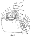
- Figure 1 is a fragmentary partially sectioned end elevational view of a three-bank radial reciprocating compressor incorporating the capacity modulation system in accordance with the present invention
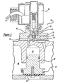
- Figure 2 is an enlarged cross-sectional view of the internal unloader valve shown in Figure 1 in a full capacity position;
- Figure 3 is an enlarged cross-sectional view of the internal unloader valve shown in Figure 2 with the unloader valve in a reduced capacity position;
- Figure 4 is an enlarged cross-sectional view of an internal unloader valve in accordance with another embodiment of the present invention with the unloader valve in a full capacity position;
- Figure 5 is an enlarged cross-sectional view of the internal unloader valve shown in Figure 4 with the unloader valve in a reduced capacity position.
- FIG. 1 a body or cylinder block portion of a multicylinder refrigeration compressor in accordance with the present invention and which is designated generally by the reference numeral 10.
- Compressor 10 illustrates three cylindrical banks 12, 14 and 16. Although only cylindrical banks 14 and 16 are illustrated, it is to be understood that each cylinder bank may contain one, two or more cylinders and that the construction illustrated typifies known commercial practice and is merely illustrative insofar as the compressor itself is concerned.
- Cylinder bank 16 defines a compression cylinder 20 within which a piston 22 is slidingly disposed.
- Cylinder bank 14 is illustrated with a capacity control system 24 while cylinder bank 16 is illustrated without capacity control system 24.
- Cylinder bank 16 may include capacity control system 24.
- Cylinder bank 16 includes a cylinder head 26 which closes cylinder 20 and which defines a suction chamber 28 and a discharge chamber 30.
- a suction valve 32 controls the communication between suction chamber 28 and cylinder 20 and a discharge valve 34 controls the communication between discharge chamber 30 and cylinder 20.
- a suction passage 36 extends between suction chamber 28 and a common suction chamber (not shown) of compressor 10 which is in turn open to the inlet of the compressor.
- Discharge chamber 30 is in communication with the outlet of compressor 10 through a discharge passage (not shown).
- Capacity control system 24 comprises a cylinder head 40, a control piston assembly 42 and a solenoid valve assembly 44.
- Cylinder head 40 closes cylinder 20 and it defines a suction chamber 46 and a discharge chamber 48.
- a suction valve 32 controls the communication between suction chamber 46 and cylinder 20 and a discharge valve 34 controls the communication between discharge chamber 48 and cylinder 20.
- a suction passage 50 extends between suction chamber 46 and the common suction chamber of compressor 10.
- Discharge chamber 48 is in communication with the outlet of compressor 10 through a discharge passage (not shown).
- Cylinder head 40 defines a discharge pressure passage 52 which extends between discharge chamber 48 and solenoid valve assembly 44, a suction pressure passage 54 ( Figure 2) which extends between suction chamber 46 and solenoid valve assembly 44 and a control passage 56 which extends between solenoid valve assembly 44 and a control chamber 58 defined by cylinder head 40.
- Control piston assembly 42 is slidingly disposed within control chamber 58 and it comprises a valve body or piston 60 and a biasing spring 62.
- Piston 60 is slidingly disposed within control chamber 58 with a seal disposed between piston 60 and control chamber 58.
- Biasing spring 62 is disposed between piston 60 and cylinder bank 14 with a seal 64 attached to piston 60. Seal 64 engages cylinder bank 14 to block suction passage 50 when piston assembly 42 is in its closed position. Biasing spring 62 urges piston assembly 42 into an open position.
- Solenoid valve assembly 44 comprises a valve block 66 and a solenoid valve 68.
- Valve block 66 is secured to cylinder head 40 and it defines a discharge control passage 70 in communication with discharge pressure passage 52, a suction control passage 72 in communication with suction pressure passage 54 and a common control passage 74 in communication with control passage 56.
- a discharge valve seat 76 is disposed between discharge control passage 70 and common control passage 74 and a suction valve seat 78 is disposed between suction control passage 72 and common control passage 74.
- Solenoid valve 68 includes a solenoid coil 80 and a needle valve 82. Needle valve 82 is disposed between valve seats 76 and 78 and moves between a first position and a second position. In its first position, communication between discharge control passage 70 and common control passage 74 is blocked but communication between suction control passage 72 and common control passage 74 is permitted. In its second position, communication between discharge control passage 70 and common control passage 74 is permitted but communication between suction control passage 72 and common control passage 74 is prohibited. Needle valve 82 and thus solenoid valve 68 is normally biased into its first position by a biasing member 84 which allows full capacity for compressor 10. Activation of solenoid coil 80 moves needle valve 82 and thus solenoid valve 68 to its second position which results in operation of compressor 10 at a reduced capacity.
- capacity control system 24 is illustrated in its full capacity or first position.
- solenoid coil 80 is de-energized and needle valve 82 is biased against discharge valve seat 76.
- the biasing of needle valve 82 against discharge valve seat 76 closes discharge control passage 70 and opens suction control passage 72.
- control chamber 58 is in communication with the common suction chamber of compressor 10 through common control passage 74, suction valve seat 78, suction control passage 72 and suction pressure passage 54.
- Fluid at suction pressure reacts against both the upper and lower surfaces of piston 60 and piston 60 is urged away from cylinder bank 14 by biasing spring 62.
- the movement of piston 60 away from cylinder bank 14 places suction passage 50 in communication with suction chamber 46 allowing for the free flow of suction gas and the full capacity operation of cylinder bank 14.
- capacity control system 24 is illustrated in its reduced capacity or second position.
- solenoid coil 80 is energized and needle valve 82 is biased against suction valve seat 78.
- the biasing of needle valve 82 against suction valve seat 78 closes suction control passage 72 and opens discharge control passage 70.
- control chamber 58 is in communication with discharge pressure from the outlet of compressor 10 through common control passage 74, discharge valve seat 76, discharge control passage 70 and discharge pressure passage 52. Fluid at discharge pressure reacts against the upper surface of piston 60 to urge piston 60 into engagement with cylinder bank 14 against the force produced by biasing spring 62.
- the engagement of piston 60 and seal 64 with cylinder bank 14 closes suction passage 50 which blocks fluid at suction pressure from entering suction chamber 46.
- Discharge control passage 70 is provided with an orifice 90 which limits the flow of fluid at discharge pressure from control passage 70 to control chamber 58.
- the velocity of piston 60 is reduced which then diminishes the impact force between piston 60 and cylinder bank 14.
- the diminishing of the impact force reduces damage and wear on piston 60, seal 64 and the seat on cylinder bank 14. This, in turn, significantly improves the reliability of compressor 10.
- piston 60 has a diameter of approximately one inch and a stroke of approximately 0.310 inches.
- the preferred diameter for orifice 90 is between 0.020 inches and 0.060 inches and more preferably between .030 inches and .050 inches.
- While the present invention is described as having only cylinder bank 14 incorporating capacity control system 24, it is within the scope of the present invention to include capacity control system 24 on more than one cylinder bank but not all of the cylinder blocks because discharge pressurized fluid is required for the movement of piston 60. With the present invention having three cylinder banks, the incorporation of one capacity control system allows the capacity of compressor 10 to vary between 2/3 capacity and full capacity. The incorporation of two capacity control systems 24 allows the capacity of compressor 10 to vary between 1/3 capacity and full capacity.
- Solenoid coil 80 is described as being de-energized to place needle valve 82 in a first position which provides full capacity and as being energized to place needle valve 82 in a second position which provides reduced capacity. It is within the scope of the present invention to operate solenoid coil 80 in a pulsed width modulation mode in order to provide an infinitesimal number of capacities between the fully reduced capacity and the full capacity. In this manner and by incorporating capacity control system 24 on two of the cylinder blocks, the capacity of compressor 10 can be selected at any capacity between 1/3 capacity and full capacity.
- Capacity control system 124 is the same as capacity control system 24 except that orifice 90 has been relocated from discharge control passage 70 to a gasket 92 disposed between cylinder head 40 and valve block 66.
- the operation and function of capacity control system 124 is identical to that described above for capacity control system 24.
- Figure 4 illustrates capacity control system 124 at full capacity
- Figure 5 illustrates capacity control system 124 at reduced capacity.
Landscapes
- Engineering & Computer Science (AREA)
- Mechanical Engineering (AREA)
- General Engineering & Computer Science (AREA)
- Compressors, Vaccum Pumps And Other Relevant Systems (AREA)
- Compressor (AREA)
- Control Of Positive-Displacement Pumps (AREA)
Applications Claiming Priority (2)
| Application Number | Priority Date | Filing Date | Title |
|---|---|---|---|
| US09/915,798 US6575710B2 (en) | 2001-07-26 | 2001-07-26 | Compressor with blocked suction capacity modulation |
| EP02254607A EP1279833B1 (fr) | 2001-07-26 | 2002-07-01 | Dispositif de réglage de capacité pour un compresseur |
Related Parent Applications (1)
| Application Number | Title | Priority Date | Filing Date |
|---|---|---|---|
| EP02254607A Division EP1279833B1 (fr) | 2001-07-26 | 2002-07-01 | Dispositif de réglage de capacité pour un compresseur |
Publications (3)
| Publication Number | Publication Date |
|---|---|
| EP1876354A2 true EP1876354A2 (fr) | 2008-01-09 |
| EP1876354A3 EP1876354A3 (fr) | 2008-01-23 |
| EP1876354B1 EP1876354B1 (fr) | 2009-03-18 |
Family
ID=25436262
Family Applications (2)
| Application Number | Title | Priority Date | Filing Date |
|---|---|---|---|
| EP02254607A Expired - Lifetime EP1279833B1 (fr) | 2001-07-26 | 2002-07-01 | Dispositif de réglage de capacité pour un compresseur |
| EP07020594A Expired - Lifetime EP1876354B1 (fr) | 2001-07-26 | 2002-07-01 | Compresseur doté d'une modulation de la capacité d'aspiration bloquée |
Family Applications Before (1)
| Application Number | Title | Priority Date | Filing Date |
|---|---|---|---|
| EP02254607A Expired - Lifetime EP1279833B1 (fr) | 2001-07-26 | 2002-07-01 | Dispositif de réglage de capacité pour un compresseur |
Country Status (9)
| Country | Link |
|---|---|
| US (1) | US6575710B2 (fr) |
| EP (2) | EP1279833B1 (fr) |
| KR (1) | KR100898023B1 (fr) |
| CN (2) | CN101349264B (fr) |
| AU (1) | AU2002300022B2 (fr) |
| BR (1) | BR0202856B1 (fr) |
| DE (2) | DE60224334T2 (fr) |
| ES (2) | ES2323658T3 (fr) |
| TW (1) | TW546440B (fr) |
Families Citing this family (17)
| Publication number | Priority date | Publication date | Assignee | Title |
|---|---|---|---|---|
| US6047557A (en) * | 1995-06-07 | 2000-04-11 | Copeland Corporation | Adaptive control for a refrigeration system using pulse width modulated duty cycle scroll compressor |
| US6206652B1 (en) | 1998-08-25 | 2001-03-27 | Copeland Corporation | Compressor capacity modulation |
| SE0202403L (sv) * | 2002-08-13 | 2004-02-14 | Cargine Engineering Ab | Styrmetid för reglering av gasflödet vid en kompressor |
| GB0602111D0 (en) * | 2006-02-02 | 2006-03-15 | Artemis Intelligent Power Ltd | Operating method for a hydraulic machine |
| US8506262B2 (en) * | 2007-05-11 | 2013-08-13 | Schlumberger Technology Corporation | Methods of use for a positive displacement pump having an externally assisted valve |
| US8317498B2 (en) * | 2007-05-11 | 2012-11-27 | Schlumberger Technology Corporation | Valve-seat interface architecture |
| US8157538B2 (en) * | 2007-07-23 | 2012-04-17 | Emerson Climate Technologies, Inc. | Capacity modulation system for compressor and method |
| BRPI1007407A2 (pt) * | 2009-01-27 | 2016-02-16 | Emerson Climate Technologies | sistema e método de descarregamento para um compressor |
| EP2452073B1 (fr) * | 2009-07-06 | 2019-05-08 | Carrier Corporation | Soupape de décompression de dérivation pour régulation de la capacité d un compresseur |
| EP2456980B1 (fr) * | 2009-07-20 | 2019-06-26 | Carrier Corporation | Soupape de décompression à coupure d'aspiration pour commande de capacité de compresseur |
| AT509878B1 (de) * | 2010-12-15 | 2011-12-15 | Hoerbiger Kompressortech Hold | Saugventil mit abhebegreifer |
| US10378533B2 (en) * | 2011-12-06 | 2019-08-13 | Bitzer Us, Inc. | Control for compressor unloading system |
| US9835147B2 (en) * | 2013-01-02 | 2017-12-05 | Quincy Compressor Llc | Dual control valve for reciprocating compressor unloader system |
| AT513603B1 (de) * | 2013-08-08 | 2014-06-15 | Hoerbiger Kompressortech Hold | Hubkolbenkompressor mit Kapazitätsregelung |
| US20160298763A1 (en) | 2015-04-09 | 2016-10-13 | Bendix Commercial Vehicle Systems Llc | Piston assembly for an unloader valve of an air compressor |
| DE112022002701A5 (de) | 2021-05-19 | 2024-03-14 | Hoerbiger Wien Gmbh | Absperrventil für einen Kolbenkompressor |
| US11655813B2 (en) * | 2021-07-29 | 2023-05-23 | Emerson Climate Technologies, Inc. | Compressor modulation system with multi-way valve |
Family Cites Families (7)
| Publication number | Priority date | Publication date | Assignee | Title |
|---|---|---|---|---|
| US3119550A (en) * | 1961-02-09 | 1964-01-28 | Carrier Corp | Compressor capacity control |
| US3303988A (en) * | 1964-01-08 | 1967-02-14 | Chrysler Corp | Compressor capacity control |
| US3578883A (en) * | 1969-05-14 | 1971-05-18 | Copeland Refrigeration Corp | Unloader for multicylinder refrigeration compressors |
| US3844686A (en) * | 1973-06-04 | 1974-10-29 | Carrier Corp | Capacity control device for reciprocating compressor |
| US4432705A (en) * | 1978-09-20 | 1984-02-21 | Carrier Corporation | Refrigeration compressor capacity control means and method |
| ZA794377B (en) * | 1978-09-20 | 1980-11-26 | Carrier Corp | Refrigeration compressor capacity control means and method |
| JP3820766B2 (ja) * | 1998-03-06 | 2006-09-13 | 株式会社豊田自動織機 | 圧縮機 |
-
2001
- 2001-07-26 US US09/915,798 patent/US6575710B2/en not_active Expired - Lifetime
-
2002
- 2002-04-18 KR KR1020020021127A patent/KR100898023B1/ko not_active Expired - Fee Related
- 2002-05-16 TW TW091110248A patent/TW546440B/zh not_active IP Right Cessation
- 2002-07-01 ES ES07020594T patent/ES2323658T3/es not_active Expired - Lifetime
- 2002-07-01 DE DE60224334T patent/DE60224334T2/de not_active Expired - Fee Related
- 2002-07-01 EP EP02254607A patent/EP1279833B1/fr not_active Expired - Lifetime
- 2002-07-01 ES ES02254607T patent/ES2296876T3/es not_active Expired - Lifetime
- 2002-07-01 DE DE60231669T patent/DE60231669D1/de not_active Expired - Lifetime
- 2002-07-01 EP EP07020594A patent/EP1876354B1/fr not_active Expired - Lifetime
- 2002-07-09 AU AU2002300022A patent/AU2002300022B2/en not_active Ceased
- 2002-07-23 BR BRPI0202856-5A patent/BR0202856B1/pt not_active IP Right Cessation
- 2002-07-26 CN CN2008101259465A patent/CN101349264B/zh not_active Expired - Lifetime
- 2002-07-26 CN CNB021269823A patent/CN100406732C/zh not_active Expired - Lifetime
Also Published As
| Publication number | Publication date |
|---|---|
| AU2002300022B2 (en) | 2008-02-21 |
| US6575710B2 (en) | 2003-06-10 |
| DE60224334D1 (de) | 2008-02-14 |
| EP1279833A3 (fr) | 2004-11-10 |
| BR0202856A (pt) | 2003-05-20 |
| CN101349264A (zh) | 2009-01-21 |
| BR0202856B1 (pt) | 2011-05-31 |
| EP1279833B1 (fr) | 2008-01-02 |
| CN1400387A (zh) | 2003-03-05 |
| US20030021703A1 (en) | 2003-01-30 |
| EP1876354A3 (fr) | 2008-01-23 |
| KR20030011221A (ko) | 2003-02-07 |
| CN100406732C (zh) | 2008-07-30 |
| EP1279833A2 (fr) | 2003-01-29 |
| CN101349264B (zh) | 2011-07-06 |
| ES2296876T3 (es) | 2008-05-01 |
| EP1876354B1 (fr) | 2009-03-18 |
| ES2323658T3 (es) | 2009-07-22 |
| DE60224334T2 (de) | 2008-12-11 |
| KR100898023B1 (ko) | 2009-05-19 |
| TW546440B (en) | 2003-08-11 |
| DE60231669D1 (de) | 2009-04-30 |
Similar Documents
| Publication | Publication Date | Title |
|---|---|---|
| EP1876354A2 (fr) | Compresseur doté d'une modulation de la capacité d'aspiration bloquée | |
| US6257848B1 (en) | Compressor having a control valve in a suction passage thereof | |
| US5147190A (en) | Increased efficiency valve system for a fluid pumping assembly | |
| US5282329A (en) | Solenoid type control valve | |
| US6485267B1 (en) | Control valve for variable capacity compressors | |
| EP2456980B1 (fr) | Soupape de décompression à coupure d'aspiration pour commande de capacité de compresseur | |
| US4685489A (en) | Valve assembly and compressor modulation apparatus | |
| US3578883A (en) | Unloader for multicylinder refrigeration compressors | |
| KR20020062678A (ko) | 용량가변형 압축기의 제어밸브 | |
| US20090032750A1 (en) | Control valve for variable capacity compressors | |
| US6769667B2 (en) | Control valve for variable-capacity compressor | |
| US7364413B2 (en) | Reciprocating compressor with enlarged valve seat area | |
| US6209793B1 (en) | Thermostatic expansion valve in which a valve seat is movable in a flow direction of a refrigerant | |
| US4537566A (en) | Valve assembly for a compressor | |
| EP0771948A1 (fr) | Dispositif de réglage de la capacité d'un compresseur à capacité variable | |
| US20040191078A1 (en) | Control valve for variable displacement compressor | |
| US7364408B2 (en) | Crank case shut off valve | |
| US3626979A (en) | Fluit compression system control | |
| US7232294B2 (en) | Compressor having a discharge valve mechanism including a valve retainer having a specially-designed curved surface | |
| US6776585B2 (en) | Control valve for a wobbleplate compressor | |
| US20080206074A1 (en) | Compressor, Especially Axial Piston Compressor for a Vehicle Air Conditioning System | |
| JP4049888B2 (ja) | 容量可変斜板式コンプレッサ | |
| JP2002155857A (ja) | 可変容量型圧縮機 | |
| JP2001107867A (ja) | エアコンプレッサ | |
| JPS60249775A (ja) | バルブ装置 |
Legal Events
| Date | Code | Title | Description |
|---|---|---|---|
| PUAI | Public reference made under article 153(3) epc to a published international application that has entered the european phase |
Free format text: ORIGINAL CODE: 0009012 |
|
| PUAL | Search report despatched |
Free format text: ORIGINAL CODE: 0009013 |
|
| AC | Divisional application: reference to earlier application |
Ref document number: 1279833 Country of ref document: EP Kind code of ref document: P |
|
| AK | Designated contracting states |
Kind code of ref document: A2 Designated state(s): DE ES FR IT |
|
| AK | Designated contracting states |
Kind code of ref document: A3 Designated state(s): DE ES FR IT |
|
| 17P | Request for examination filed |
Effective date: 20080523 |
|
| GRAP | Despatch of communication of intention to grant a patent |
Free format text: ORIGINAL CODE: EPIDOSNIGR1 |
|
| AKX | Designation fees paid |
Designated state(s): DE ES FR IT |
|
| GRAS | Grant fee paid |
Free format text: ORIGINAL CODE: EPIDOSNIGR3 |
|
| GRAA | (expected) grant |
Free format text: ORIGINAL CODE: 0009210 |
|
| AC | Divisional application: reference to earlier application |
Ref document number: 1279833 Country of ref document: EP Kind code of ref document: P |
|
| AK | Designated contracting states |
Kind code of ref document: B1 Designated state(s): DE ES FR IT |
|
| REF | Corresponds to: |
Ref document number: 60231669 Country of ref document: DE Date of ref document: 20090430 Kind code of ref document: P |
|
| REG | Reference to a national code |
Ref country code: ES Ref legal event code: FG2A Ref document number: 2323658 Country of ref document: ES Kind code of ref document: T3 |
|
| PLBE | No opposition filed within time limit |
Free format text: ORIGINAL CODE: 0009261 |
|
| STAA | Information on the status of an ep patent application or granted ep patent |
Free format text: STATUS: NO OPPOSITION FILED WITHIN TIME LIMIT |
|
| 26N | No opposition filed |
Effective date: 20091221 |
|
| PGFP | Annual fee paid to national office [announced via postgrant information from national office to epo] |
Ref country code: ES Payment date: 20130726 Year of fee payment: 12 |
|
| PGFP | Annual fee paid to national office [announced via postgrant information from national office to epo] |
Ref country code: IT Payment date: 20130724 Year of fee payment: 12 |
|
| PG25 | Lapsed in a contracting state [announced via postgrant information from national office to epo] |
Ref country code: IT Free format text: LAPSE BECAUSE OF NON-PAYMENT OF DUE FEES Effective date: 20140701 |
|
| REG | Reference to a national code |
Ref country code: FR Ref legal event code: PLFP Year of fee payment: 15 |
|
| PG25 | Lapsed in a contracting state [announced via postgrant information from national office to epo] |
Ref country code: ES Free format text: LAPSE BECAUSE OF NON-PAYMENT OF DUE FEES Effective date: 20140702 |
|
| REG | Reference to a national code |
Ref country code: FR Ref legal event code: PLFP Year of fee payment: 16 |
|
| REG | Reference to a national code |
Ref country code: FR Ref legal event code: PLFP Year of fee payment: 17 |
|
| PGFP | Annual fee paid to national office [announced via postgrant information from national office to epo] |
Ref country code: FR Payment date: 20210623 Year of fee payment: 20 |
|
| PGFP | Annual fee paid to national office [announced via postgrant information from national office to epo] |
Ref country code: DE Payment date: 20210622 Year of fee payment: 20 |
|
| REG | Reference to a national code |
Ref country code: DE Ref legal event code: R071 Ref document number: 60231669 Country of ref document: DE |