EP1876358A1 - Spiralverdichter mit Schalldämpfer - Google Patents
Spiralverdichter mit Schalldämpfer Download PDFInfo
- Publication number
- EP1876358A1 EP1876358A1 EP06013759A EP06013759A EP1876358A1 EP 1876358 A1 EP1876358 A1 EP 1876358A1 EP 06013759 A EP06013759 A EP 06013759A EP 06013759 A EP06013759 A EP 06013759A EP 1876358 A1 EP1876358 A1 EP 1876358A1
- Authority
- EP
- European Patent Office
- Prior art keywords
- muffler
- chamber
- wall
- scroll
- fixed scroll
- Prior art date
- Legal status (The legal status is an assumption and is not a legal conclusion. Google has not performed a legal analysis and makes no representation as to the accuracy of the status listed.)
- Granted
Links
Images

Classifications
-
- F—MECHANICAL ENGINEERING; LIGHTING; HEATING; WEAPONS; BLASTING
- F04—POSITIVE - DISPLACEMENT MACHINES FOR LIQUIDS; PUMPS FOR LIQUIDS OR ELASTIC FLUIDS
- F04C—ROTARY-PISTON, OR OSCILLATING-PISTON, POSITIVE-DISPLACEMENT MACHINES FOR LIQUIDS; ROTARY-PISTON, OR OSCILLATING-PISTON, POSITIVE-DISPLACEMENT PUMPS
- F04C29/00—Component parts, details or accessories of pumps or pumping installations, not provided for in groups F04C18/00 - F04C28/00
- F04C29/06—Silencing
- F04C29/068—Silencing the silencing means being arranged inside the pump housing
-
- F—MECHANICAL ENGINEERING; LIGHTING; HEATING; WEAPONS; BLASTING
- F04—POSITIVE - DISPLACEMENT MACHINES FOR LIQUIDS; PUMPS FOR LIQUIDS OR ELASTIC FLUIDS
- F04C—ROTARY-PISTON, OR OSCILLATING-PISTON, POSITIVE-DISPLACEMENT MACHINES FOR LIQUIDS; ROTARY-PISTON, OR OSCILLATING-PISTON, POSITIVE-DISPLACEMENT PUMPS
- F04C23/00—Combinations of two or more pumps, each being of rotary-piston or oscillating-piston type, specially adapted for elastic fluids; Pumping installations specially adapted for elastic fluids; Multi-stage pumps specially adapted for elastic fluids
- F04C23/008—Hermetic pumps
-
- F—MECHANICAL ENGINEERING; LIGHTING; HEATING; WEAPONS; BLASTING
- F04—POSITIVE - DISPLACEMENT MACHINES FOR LIQUIDS; PUMPS FOR LIQUIDS OR ELASTIC FLUIDS
- F04C—ROTARY-PISTON, OR OSCILLATING-PISTON, POSITIVE-DISPLACEMENT MACHINES FOR LIQUIDS; ROTARY-PISTON, OR OSCILLATING-PISTON, POSITIVE-DISPLACEMENT PUMPS
- F04C29/00—Component parts, details or accessories of pumps or pumping installations, not provided for in groups F04C18/00 - F04C28/00
- F04C29/06—Silencing
- F04C29/065—Noise dampening volumes, e.g. muffler chambers
-
- F—MECHANICAL ENGINEERING; LIGHTING; HEATING; WEAPONS; BLASTING
- F04—POSITIVE - DISPLACEMENT MACHINES FOR LIQUIDS; PUMPS FOR LIQUIDS OR ELASTIC FLUIDS
- F04C—ROTARY-PISTON, OR OSCILLATING-PISTON, POSITIVE-DISPLACEMENT MACHINES FOR LIQUIDS; ROTARY-PISTON, OR OSCILLATING-PISTON, POSITIVE-DISPLACEMENT PUMPS
- F04C18/00—Rotary-piston pumps specially adapted for elastic fluids
- F04C18/02—Rotary-piston pumps specially adapted for elastic fluids of arcuate-engagement type, i.e. with circular translatory movement of co-operating members, each member having the same number of teeth or tooth-equivalents
- F04C18/0207—Rotary-piston pumps specially adapted for elastic fluids of arcuate-engagement type, i.e. with circular translatory movement of co-operating members, each member having the same number of teeth or tooth-equivalents both members having co-operating elements in spiral form
Definitions
- the present invention relates to a muffler of a scroll compressor, and more particularly, to a muffler of a scroll compressor, which can achieve: reduction of operational noise; sufficient separation of oil contained in discharge gas; and efficient isolation between a discharge pressure inside the muffler and outside suction pressure.
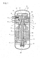
- a general scroll compressor as shown in FIG. 1, includes a main frame 2 and sub frame 3 mounted in a shell 1 at upper and lower locations of the shell 1, a stator 4 press-fitted in the shell 1 between the main frame 2 and the sub frame 3, and a rotor 5 disposed in the stator 4 and adapted to rotate by power applied thereto.
- a vertical crank shaft 6 is fixedly inserted into the center of the rotor 5 such that opposite ends thereof are rotatably supported by the main frame 2 and sub frame 3, respectively. Then, the vertical crank shaft 6 is rotated along with the rotor 5.
- the scroll compressor further includes a compression unit including an orbiting scroll 7 disposed on an upper end surface of the main frame 2, and a fixed scroll 8 located over the orbiting scroll 7 to be secured to an inner periphery of the shell 1.
- the orbiting scroll 7 has a lower portion coupled to the crank shaft 6 and an upper portion forming an involute orbiting wrap 7a.
- the fixed scroll 8 has a fixed wrap 8a configured to be engaged with the orbiting wrap 7a in such a manner that a compression chamber 21 is defined between the fixed wrap 8a and the orbiting wrap 7a.
- a structure for coupling the crank shaft 6 with the orbiting scroll 7 includes a hollow boss 7b, which protrudes downward from the center of a lower portion of the orbiting scroll 7, and a crank pin 10 which protrudes upward from the center of an upper end surface of the crank shaft 6 by a predetermined distance to be inserted into the hollow boss 7b.
- a bearing 11 is forcibly press-fitted in the boss 7b, and an eccentric bush 12 is rotatably coupled around the crank pin 10.
- an Oldham's ring 9 serving as anti-rotation device is interposed between the main frame 2 and the orbiting scroll 7.
- An oil supply path 6a is vertically defined in the crank shaft 6 throughout the overall length of the crank shaft 6.
- a pair of upper and lower balancing weights 13 and 14 are arranged above and below the rotor 5, respectively, to prevent unbalanced rotation of the crank shaft 6 that may be caused by the crank pin 10.
- a muffler 22 is mounted above the fixed scroll 8.
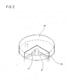
- the muffler 22, as shown in FIG. 2, takes the form of a cover.
- the muffler 22 has a function of isolating a suction pressure from a discharge pressure, namely, a low-pressure portion from a high pressure portion when the scroll compressor has a high-pressure structure wherein a lower region of the compressor is filled with the high-pressure refrigerant gas discharged from the compression unit.
- the fixed scroll 8 has guidance paths 23 to guide the compressed refrigerant gas in the muffler 22 into the lower region of the compressor.
- reference numerals 15 and 16 designate a suction pipe and discharge pipe, respectively
- reference numeral 18 designates a discharge chamber
- reference numerals 19 and 20 designate oil and an oil propeller, respectively.
- the compression chamber 21, which is defined between the orbiting wrap 7a and the fixed wrap 8a, has a volume reduction by continuous orbiting movement of the orbiting scroll 7, resulting in compression of refrigerant gas suctioned thereinto.
- the compressed high-pressure refrigerant gas is discharged into the discharge chamber 18 through the outlet 17 of the fixed scroll 8.
- the refrigerant gas in the discharge chamber 18 is guided into the lower region of the compressor through the guidance paths 23 of the fixed scroll 8, and thereafter, is discharged to the outside through the discharge pipe 16.
- the muffler 22 which takes the form of a cover as shown in FIG. 2, is mounted on the fixed scroll 8.
- the muffler 22 functions to reduce noise and also, to isolate a suction pressure from a discharge pressure, namely, a low-pressure portion from a high pressure portion when the scroll compressor has a high-pressure structure wherein the lower region of the compressor is filled with the high-pressure refrigerant gas discharged from the compression unit.
- the guidance paths 23 are defined in the fixed scroll 8.
- the above described conventional muffler for use with the scroll compressor has an unsophisticated cover structure simply defining a single shield wall, and therefore, cannot achieve a sufficient noise transmission loss (TL). Further, the conventional muffler has no function of sufficiently separating oil contained the high-pressure refrigerant gas discharged from the outlet of the fixed scroll. Furthermore, the conventional muffler cannot achieve an accurate isolation between a discharge pressure inside the muffler and outside suction pressure. For these several problems, the above described conventional muffler has been proved to cause deterioration in the performance and reliability of scroll compressors.
- the present invention has been made in view of the above problems, and it is an object of the present invention to provide a muffler of a scroll compressor, which can prevent high-pressure refrigerant gas, which is compressed in a compression unit, from imparting a direct shock to a top cap of a compressor shell in the course of being discharged through an outlet of a fixed scroll, thereby achieving a sufficient noise transmission loss.
- a muffler of a scroll compressor comprising: a first muffler having a pair of chambers defined above an outlet of a fixed scroll to communicate with the outlet and a gas passage hole formed at the center of an upper end thereof; and a second muffler located around the first muffler to be spaced apart from the gas passage hole of the first muffler and having a chamber communicating with one or more guidance paths of the fixed scroll.
- the chambers of the first muffler may include a lower first chamber and an upper second chamber.
- the second chamber may be defined by an inclined conical wall.
- the inclined conical wall may have pleats.
- the second muffler may be defined by a planar gas confronting wall forming the center of a top thereof and a curved wall extending downward from the planar gas confronting wall to have a gentle curvature.
- the curved wall may have pleats.
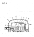
- the muffler includes a first muffler 24 and a second muffler 30.
- the first muffler 24 internally defines a pair of chambers above the outlet 17 of the fixed scroll 8 to communicate with the outlet 17, and is formed with a gas passage hole 27 at the center of an upper end thereof.
- the second muffler 30 is located around the first muffler 24 to be spaced apart from the gas passage hole 27 of the first muffler 24.
- the second muffler 30 internally defines a chamber, i.e. third chamber 31, including the guidance paths 23 of the fixed scroll 8.
- the chambers of the first muffler 24 include a lower first chamber 25 and upper second chamber 26.
- the second chamber 26 is defined by an inclined conical wall 28.
- the second muffler 30 has a planar gas confronting wall 32 forming the center of a top thereof, and a curved wall 33 extending downward from the planar gas confronting wall 32 to have a gentle curvature.
- the high-pressure refrigerant gas first circulates the first and second chambers 25 and 26 of the first muffler 24 in this sequence, and then, is introduced into the second muffler 30 through the gas passage hole 27 of the second chamber 26, so as to circulate in the second muffler 30.
- the refrigerant gas, which circulates in the first and second chambers 25 and 26, comes into contact with the inclined wall 28 of the second chamber 26, which is conically extended upward from the vertical wall of the first chamber 25, oil contained in the refrigerant gas is able to be separated.
- the gas which is discharged from the gas passage hole 27 of the second chamber 26 to be introduced into the second muffler 30, circulates from the approximately circular planar gas confronting wall 32, which forms the center of the top of the second muffler 30, toward the bottom of the second muffler 30 along the circumferential curved wall 33, and thereafter, is guided into the lower region of the compressor through the guidance paths 23 of the fixed scroll 8.
- the refrigerant gas While circulating in the second muffler 30, similarly, the refrigerant gas is subjected to a secondary oil separation via contact with the wall of the second muffler 30.
- the double structure muffler of the present invention has the effect of achieving an outstanding noise transmission loss.
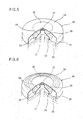
- FIG. 5 is a semi-sectional perspective view illustrating a muffler according to a second embodiment of the present invention.
- the muffler of the present embodiment includes the first muffler 24 and second muffler 30.
- the first muffler 24 internally defines the pair of chambers above the outlet 17 of the fixed scroll 8 to communicate with the outlet 17, and is formed with the gas passage hole 27 at the center of the upper end thereof.
- the second muffler 30 is located around the first muffler 24 to be spaced,apart from the gas passage hole 27 of the first muffler 24, and internally defines the third chamber 31 including the guidance paths 23 of the fixed scroll 8.
- the chambers of the first muffler 24 include the lower first chamber 25 and upper second chamber 26, and in particular, the second chamber 26 is defined by the inclined conical wall 28.
- the second muffler 30 has the planar gas confronting wall 32 forming the center of the top thereof, and the curved wall 33 extending downward from the planar gas confronting wall 32 to have a gentle curvature.
- the inclined conical wall 28 of the first muffler 24 has pleates 29.
- FIG. 6. is a semi-sectional perspective view illustrating a muffler according to a third embodiment of the present invention.
- the muffler of the present embodiment includes the first muffler 24 and second muffler 30.
- the first muffler 24 internally defines the pair of chambers above the outlet 17 of the fixed scroll 8 to communicate with the outlet 17, and is formed with the gas passage hole 27 at the center of the upper end thereof.
- the second muffler 30 is located around the first muffler 24 to be spaced apart from the gas passage hole 27 of the first muffler 24, and internally defines the third chamber 31 including the guidance paths 23 of the fixed scroll 8.
- the chambers of the first muffler 24 include the lower first chamber 25 and upper second chamber 26, and in particular, the second chamber 26 is defined by the inclined conical wall 28.
- the second muffler 30 has the planar gas confronting wall 32 forming the center of the top thereof, and the curved wall 33 extending downward from the planar gas confronting wall 32 to have a gentle curvature.
- both the inclined conical wall 28 of the first muffler 24 and the curved wall 33 of the second muffler 30 have the pleats 29.
- the pleats 29 are formed at the inclined conical wall 28 of the second chamber 26 and the curved wall 33 of the second muffler 30, in the same manner as the second embodiment of the present invention; a contact area between the walls 28 and 33 and the refrigerant gas increases, resulting in more improved oil separation efficiency. Furthermore, the curved wall 33 of the second muffler 30 having the pleats 29 has the effect of providing the planar gas confronting wall 32, onto which the compressed refrigerant gas discharged through the gas passage hole 27 of the second chamber 26 imparts a direct shock, with shock-alleviating effect.
- the present invention provides a muffler of a scroll compressor, which has a double muffler structure internally defining three chambers.
- this double muffler structure it is possible not only to achieve a sufficient transmission loss of noise generated when compressed high-pressure refrigerant gas is discharged through an outlet of a fixed scroll, but also to achieve sufficient separation of oil contained in the gas.
- the muffler of the present invention has the effect of isolating a discharge pressure inside the muffler from an outside suction pressure with increased accuracy, resulting in an improvement in the performance and reliability of compressors.
Landscapes
- Engineering & Computer Science (AREA)
- Mechanical Engineering (AREA)
- General Engineering & Computer Science (AREA)
- Rotary Pumps (AREA)
- Applications Or Details Of Rotary Compressors (AREA)
Priority Applications (2)
| Application Number | Priority Date | Filing Date | Title |
|---|---|---|---|
| DE602006012174T DE602006012174D1 (de) | 2006-07-03 | 2006-07-03 | Spiralverdichter mit Schalldämpfer |
| EP06013759A EP1876358B1 (de) | 2006-07-03 | 2006-07-03 | Spiralverdichter mit Schalldämpfer |
Applications Claiming Priority (1)
| Application Number | Priority Date | Filing Date | Title |
|---|---|---|---|
| EP06013759A EP1876358B1 (de) | 2006-07-03 | 2006-07-03 | Spiralverdichter mit Schalldämpfer |
Publications (2)
| Publication Number | Publication Date |
|---|---|
| EP1876358A1 true EP1876358A1 (de) | 2008-01-09 |
| EP1876358B1 EP1876358B1 (de) | 2010-02-10 |
Family
ID=37564289
Family Applications (1)
| Application Number | Title | Priority Date | Filing Date |
|---|---|---|---|
| EP06013759A Ceased EP1876358B1 (de) | 2006-07-03 | 2006-07-03 | Spiralverdichter mit Schalldämpfer |
Country Status (2)
| Country | Link |
|---|---|
| EP (1) | EP1876358B1 (de) |
| DE (1) | DE602006012174D1 (de) |
Cited By (4)
| Publication number | Priority date | Publication date | Assignee | Title |
|---|---|---|---|---|
| US10180140B2 (en) | 2016-09-30 | 2019-01-15 | Ingersoll-Rand Company | Pulsation damper for compressors |
| DE102018201829A1 (de) * | 2018-02-06 | 2019-08-08 | Brose Fahrzeugteile GmbH & Co. Kommanditgesellschaft, Würzburg | Elektromotorischer Kältemittelverdichter |
| WO2021231604A1 (en) | 2020-05-13 | 2021-11-18 | Emerson Climate Technologies, Inc. | Compressor having muffler plate |
| CN113982946A (zh) * | 2021-10-28 | 2022-01-28 | 广东美芝制冷设备有限公司 | 压缩机和制冷设备 |
Families Citing this family (2)
| Publication number | Priority date | Publication date | Assignee | Title |
|---|---|---|---|---|
| EP4015824B1 (de) | 2020-12-18 | 2024-07-10 | Danfoss (Tianjin) Ltd. | Schalldämpfervorrichtung und verdichter damit |
| US12352265B2 (en) | 2023-10-12 | 2025-07-08 | Copeland Lp | Compressor having compression subassembly and methods of assembling the same |
Citations (4)
| Publication number | Priority date | Publication date | Assignee | Title |
|---|---|---|---|---|
| JPH08326668A (ja) * | 1995-06-01 | 1996-12-10 | Matsushita Electric Ind Co Ltd | スクロール圧縮機 |
| JPH11173284A (ja) * | 1997-12-10 | 1999-06-29 | Mitsubishi Electric Corp | スクロール圧縮機 |
| JPH11210660A (ja) * | 1998-01-29 | 1999-08-03 | Mitsubishi Electric Corp | スクロール圧縮機 |
| JP2004316591A (ja) * | 2003-04-18 | 2004-11-11 | Matsushita Electric Ind Co Ltd | 密閉型圧縮機 |
-
2006
- 2006-07-03 EP EP06013759A patent/EP1876358B1/de not_active Ceased
- 2006-07-03 DE DE602006012174T patent/DE602006012174D1/de active Active
Patent Citations (4)
| Publication number | Priority date | Publication date | Assignee | Title |
|---|---|---|---|---|
| JPH08326668A (ja) * | 1995-06-01 | 1996-12-10 | Matsushita Electric Ind Co Ltd | スクロール圧縮機 |
| JPH11173284A (ja) * | 1997-12-10 | 1999-06-29 | Mitsubishi Electric Corp | スクロール圧縮機 |
| JPH11210660A (ja) * | 1998-01-29 | 1999-08-03 | Mitsubishi Electric Corp | スクロール圧縮機 |
| JP2004316591A (ja) * | 2003-04-18 | 2004-11-11 | Matsushita Electric Ind Co Ltd | 密閉型圧縮機 |
Cited By (6)
| Publication number | Priority date | Publication date | Assignee | Title |
|---|---|---|---|---|
| US10180140B2 (en) | 2016-09-30 | 2019-01-15 | Ingersoll-Rand Company | Pulsation damper for compressors |
| DE102018201829A1 (de) * | 2018-02-06 | 2019-08-08 | Brose Fahrzeugteile GmbH & Co. Kommanditgesellschaft, Würzburg | Elektromotorischer Kältemittelverdichter |
| WO2021231604A1 (en) | 2020-05-13 | 2021-11-18 | Emerson Climate Technologies, Inc. | Compressor having muffler plate |
| EP4150213A4 (de) * | 2020-05-13 | 2024-05-22 | Emerson Climate Technologies, Inc. | Verdichter mit schalldämpferplatte |
| CN113982946A (zh) * | 2021-10-28 | 2022-01-28 | 广东美芝制冷设备有限公司 | 压缩机和制冷设备 |
| CN113982946B (zh) * | 2021-10-28 | 2023-02-21 | 广东美芝制冷设备有限公司 | 压缩机和制冷设备 |
Also Published As
| Publication number | Publication date |
|---|---|
| EP1876358B1 (de) | 2010-02-10 |
| DE602006012174D1 (de) | 2010-03-25 |
Similar Documents
| Publication | Publication Date | Title |
|---|---|---|
| US5055010A (en) | Suction baffle for refrigeration compressor | |
| US6071100A (en) | Scroll compressor having lubrication of the rotation preventing member | |
| US7527484B2 (en) | Muffler of scroll compressor | |
| CN106523372B (zh) | 涡旋压缩机 | |
| US9109598B2 (en) | Compressor with oil separating mechanism | |
| JPS58117378A (ja) | スクロ−ル圧縮機 | |
| AU2003211603B2 (en) | High-low pressure dome type compressor | |
| EP3553318B1 (de) | Spiralverdichter | |
| US20060073057A1 (en) | Variable capacity type orbiting vane compressor | |
| US20060177335A1 (en) | Low-pressure type orbiting vane compressor | |
| CN101936292B (zh) | 压缩机 | |
| KR102553485B1 (ko) | 고압식 스크롤 압축기 | |
| EP1876358B1 (de) | Spiralverdichter mit Schalldämpfer | |
| WO2009096206A1 (ja) | スクロール圧縮機 | |
| KR20210021876A (ko) | 압축기 | |
| JP4164917B2 (ja) | 高圧ドーム形圧縮機 | |
| JP4939239B2 (ja) | クランクシャフト | |
| JP2002257055A (ja) | スクロール圧縮機 | |
| KR102189105B1 (ko) | 압축기 | |
| US11927186B2 (en) | Scroll compressor | |
| JP4029724B2 (ja) | 密閉型圧縮機 | |
| CN101105177A (zh) | 涡卷压缩机的消声器 | |
| US12152590B2 (en) | Scroll compressor | |
| JP7223929B2 (ja) | スクロール圧縮機 | |
| CN112709701B (zh) | 压缩机组件以及具有其的设备 |
Legal Events
| Date | Code | Title | Description |
|---|---|---|---|
| PUAI | Public reference made under article 153(3) epc to a published international application that has entered the european phase |
Free format text: ORIGINAL CODE: 0009012 |
|
| AK | Designated contracting states |
Kind code of ref document: A1 Designated state(s): AT BE BG CH CY CZ DE DK EE ES FI FR GB GR HU IE IS IT LI LT LU LV MC NL PL PT RO SE SI SK TR |
|
| AX | Request for extension of the european patent |
Extension state: AL BA HR MK YU |
|
| 17P | Request for examination filed |
Effective date: 20080201 |
|
| 17Q | First examination report despatched |
Effective date: 20080305 |
|
| AKX | Designation fees paid |
Designated state(s): DE GB IT |
|
| GRAP | Despatch of communication of intention to grant a patent |
Free format text: ORIGINAL CODE: EPIDOSNIGR1 |
|
| GRAS | Grant fee paid |
Free format text: ORIGINAL CODE: EPIDOSNIGR3 |
|
| GRAA | (expected) grant |
Free format text: ORIGINAL CODE: 0009210 |
|
| AK | Designated contracting states |
Kind code of ref document: B1 Designated state(s): DE GB IT |
|
| REG | Reference to a national code |
Ref country code: GB Ref legal event code: FG4D |
|
| REF | Corresponds to: |
Ref document number: 602006012174 Country of ref document: DE Date of ref document: 20100325 Kind code of ref document: P |
|
| PLBE | No opposition filed within time limit |
Free format text: ORIGINAL CODE: 0009261 |
|
| STAA | Information on the status of an ep patent application or granted ep patent |
Free format text: STATUS: NO OPPOSITION FILED WITHIN TIME LIMIT |
|
| 26N | No opposition filed |
Effective date: 20101111 |
|
| PGFP | Annual fee paid to national office [announced via postgrant information from national office to epo] |
Ref country code: GB Payment date: 20140611 Year of fee payment: 9 |
|
| PGFP | Annual fee paid to national office [announced via postgrant information from national office to epo] |
Ref country code: DE Payment date: 20140611 Year of fee payment: 9 |
|
| PGFP | Annual fee paid to national office [announced via postgrant information from national office to epo] |
Ref country code: IT Payment date: 20140716 Year of fee payment: 9 |
|
| REG | Reference to a national code |
Ref country code: DE Ref legal event code: R119 Ref document number: 602006012174 Country of ref document: DE |
|
| GBPC | Gb: european patent ceased through non-payment of renewal fee |
Effective date: 20150703 |
|
| PG25 | Lapsed in a contracting state [announced via postgrant information from national office to epo] |
Ref country code: GB Free format text: LAPSE BECAUSE OF NON-PAYMENT OF DUE FEES Effective date: 20150703 Ref country code: IT Free format text: LAPSE BECAUSE OF NON-PAYMENT OF DUE FEES Effective date: 20150703 Ref country code: DE Free format text: LAPSE BECAUSE OF NON-PAYMENT OF DUE FEES Effective date: 20160202 |