EP1876389A1 - Beleuchtungssystem für Anzeigegerät - Google Patents
Beleuchtungssystem für Anzeigegerät Download PDFInfo
- Publication number
- EP1876389A1 EP1876389A1 EP06116675A EP06116675A EP1876389A1 EP 1876389 A1 EP1876389 A1 EP 1876389A1 EP 06116675 A EP06116675 A EP 06116675A EP 06116675 A EP06116675 A EP 06116675A EP 1876389 A1 EP1876389 A1 EP 1876389A1
- Authority
- EP
- European Patent Office
- Prior art keywords
- lighting
- lighting system
- unit
- lighting unit
- track assembly
- Prior art date
- Legal status (The legal status is an assumption and is not a legal conclusion. Google has not performed a legal analysis and makes no representation as to the accuracy of the status listed.)
- Withdrawn
Links
- 230000000694 effects Effects 0.000 claims description 13
- 238000012545 processing Methods 0.000 claims description 4
- 229910052751 metal Inorganic materials 0.000 claims description 3
- 239000002184 metal Substances 0.000 claims description 3
- 238000001816 cooling Methods 0.000 description 7
- 238000000034 method Methods 0.000 description 7
- 230000001276 controlling effect Effects 0.000 description 4
- 230000008878 coupling Effects 0.000 description 4
- 238000010168 coupling process Methods 0.000 description 4
- 238000005859 coupling reaction Methods 0.000 description 4
- 238000005286 illumination Methods 0.000 description 4
- 238000012423 maintenance Methods 0.000 description 3
- 238000005057 refrigeration Methods 0.000 description 3
- 230000002730 additional effect Effects 0.000 description 2
- RYGMFSIKBFXOCR-UHFFFAOYSA-N Copper Chemical compound [Cu] RYGMFSIKBFXOCR-UHFFFAOYSA-N 0.000 description 1
- 241001085205 Prenanthella exigua Species 0.000 description 1
- 230000032683 aging Effects 0.000 description 1
- 239000004411 aluminium Substances 0.000 description 1
- 229910052782 aluminium Inorganic materials 0.000 description 1
- XAGFODPZIPBFFR-UHFFFAOYSA-N aluminium Chemical compound [Al] XAGFODPZIPBFFR-UHFFFAOYSA-N 0.000 description 1
- 230000000712 assembly Effects 0.000 description 1
- 238000000429 assembly Methods 0.000 description 1
- 230000005540 biological transmission Effects 0.000 description 1
- 230000004397 blinking Effects 0.000 description 1
- 238000004891 communication Methods 0.000 description 1
- 239000004020 conductor Substances 0.000 description 1
- 238000010276 construction Methods 0.000 description 1
- 229910052802 copper Inorganic materials 0.000 description 1
- 239000010949 copper Substances 0.000 description 1
- 238000013461 design Methods 0.000 description 1
- 239000011521 glass Substances 0.000 description 1
- 238000010438 heat treatment Methods 0.000 description 1
- 230000001795 light effect Effects 0.000 description 1
- 230000013011 mating Effects 0.000 description 1
- 230000001360 synchronised effect Effects 0.000 description 1
Images
Classifications
-
- F—MECHANICAL ENGINEERING; LIGHTING; HEATING; WEAPONS; BLASTING
- F21—LIGHTING
- F21V—FUNCTIONAL FEATURES OR DETAILS OF LIGHTING DEVICES OR SYSTEMS THEREOF; STRUCTURAL COMBINATIONS OF LIGHTING DEVICES WITH OTHER ARTICLES, NOT OTHERWISE PROVIDED FOR
- F21V21/00—Supporting, suspending, or attaching arrangements for lighting devices; Hand grips
- F21V21/34—Supporting elements displaceable along a guiding element
- F21V21/35—Supporting elements displaceable along a guiding element with direct electrical contact between the supporting element and electric conductors running along the guiding element
-
- A—HUMAN NECESSITIES
- A47—FURNITURE; DOMESTIC ARTICLES OR APPLIANCES; COFFEE MILLS; SPICE MILLS; SUCTION CLEANERS IN GENERAL
- A47F—SPECIAL FURNITURE, FITTINGS, OR ACCESSORIES FOR SHOPS, STOREHOUSES, BARS, RESTAURANTS OR THE LIKE; PAYING COUNTERS
- A47F11/00—Arrangements in shop windows, shop floors or show cases
- A47F11/06—Means for bringing about special optical effects
- A47F11/10—Arrangements of light sources
-
- F—MECHANICAL ENGINEERING; LIGHTING; HEATING; WEAPONS; BLASTING
- F21—LIGHTING
- F21S—NON-PORTABLE LIGHTING DEVICES; SYSTEMS THEREOF; VEHICLE LIGHTING DEVICES SPECIALLY ADAPTED FOR VEHICLE EXTERIORS
- F21S2/00—Systems of lighting devices, not provided for in main groups F21S4/00 - F21S10/00 or F21S19/00, e.g. of modular construction
- F21S2/005—Systems of lighting devices, not provided for in main groups F21S4/00 - F21S10/00 or F21S19/00, e.g. of modular construction of modular construction
-
- F—MECHANICAL ENGINEERING; LIGHTING; HEATING; WEAPONS; BLASTING
- F21—LIGHTING
- F21V—FUNCTIONAL FEATURES OR DETAILS OF LIGHTING DEVICES OR SYSTEMS THEREOF; STRUCTURAL COMBINATIONS OF LIGHTING DEVICES WITH OTHER ARTICLES, NOT OTHERWISE PROVIDED FOR
- F21V23/00—Arrangement of electric circuit elements in or on lighting devices
- F21V23/04—Arrangement of electric circuit elements in or on lighting devices the elements being switches
- F21V23/0435—Arrangement of electric circuit elements in or on lighting devices the elements being switches activated by remote control means
-
- H—ELECTRICITY
- H01—ELECTRIC ELEMENTS
- H01R—ELECTRICALLY-CONDUCTIVE CONNECTIONS; STRUCTURAL ASSOCIATIONS OF A PLURALITY OF MUTUALLY-INSULATED ELECTRICAL CONNECTING ELEMENTS; COUPLING DEVICES; CURRENT COLLECTORS
- H01R13/00—Details of coupling devices of the kinds covered by groups H01R12/70 or H01R24/00 - H01R33/00
- H01R13/66—Structural association with built-in electrical component
- H01R13/717—Structural association with built-in electrical component with built-in light source
- H01R13/7175—Light emitting diodes (LEDs)
-
- H—ELECTRICITY
- H01—ELECTRIC ELEMENTS
- H01R—ELECTRICALLY-CONDUCTIVE CONNECTIONS; STRUCTURAL ASSOCIATIONS OF A PLURALITY OF MUTUALLY-INSULATED ELECTRICAL CONNECTING ELEMENTS; COUPLING DEVICES; CURRENT COLLECTORS
- H01R25/00—Coupling parts adapted for simultaneous co-operation with two or more identical counterparts, e.g. for distributing energy to two or more circuits
- H01R25/14—Rails or bus-bars constructed so that the counterparts can be connected thereto at any point along their length
- H01R25/147—Low voltage devices, i.e. safe to touch live conductors
-
- H—ELECTRICITY
- H05—ELECTRIC TECHNIQUES NOT OTHERWISE PROVIDED FOR
- H05B—ELECTRIC HEATING; ELECTRIC LIGHT SOURCES NOT OTHERWISE PROVIDED FOR; CIRCUIT ARRANGEMENTS FOR ELECTRIC LIGHT SOURCES, IN GENERAL
- H05B45/00—Circuit arrangements for operating light-emitting diodes [LED]
- H05B45/30—Driver circuits
-
- F—MECHANICAL ENGINEERING; LIGHTING; HEATING; WEAPONS; BLASTING
- F21—LIGHTING
- F21V—FUNCTIONAL FEATURES OR DETAILS OF LIGHTING DEVICES OR SYSTEMS THEREOF; STRUCTURAL COMBINATIONS OF LIGHTING DEVICES WITH OTHER ARTICLES, NOT OTHERWISE PROVIDED FOR
- F21V21/00—Supporting, suspending, or attaching arrangements for lighting devices; Hand grips
- F21V21/14—Adjustable mountings
- F21V21/30—Pivoted housings or frames
-
- F—MECHANICAL ENGINEERING; LIGHTING; HEATING; WEAPONS; BLASTING
- F21—LIGHTING
- F21W—INDEXING SCHEME ASSOCIATED WITH SUBCLASSES F21K, F21L, F21S and F21V, RELATING TO USES OR APPLICATIONS OF LIGHTING DEVICES OR SYSTEMS
- F21W2131/00—Use or application of lighting devices or systems not provided for in codes F21W2102/00-F21W2121/00
- F21W2131/30—Lighting for domestic or personal use
- F21W2131/305—Lighting for domestic or personal use for refrigerators
-
- F—MECHANICAL ENGINEERING; LIGHTING; HEATING; WEAPONS; BLASTING
- F21—LIGHTING
- F21W—INDEXING SCHEME ASSOCIATED WITH SUBCLASSES F21K, F21L, F21S and F21V, RELATING TO USES OR APPLICATIONS OF LIGHTING DEVICES OR SYSTEMS
- F21W2131/00—Use or application of lighting devices or systems not provided for in codes F21W2102/00-F21W2121/00
- F21W2131/40—Lighting for industrial, commercial, recreational or military use
- F21W2131/405—Lighting for industrial, commercial, recreational or military use for shop-windows or displays
Definitions
- the present invention relates to a lighting system for a display assembly, in particular for a dispensing apparatus such as a chilled vending machine, comprising a track assembly and one or more LED lighting units releasably attached or attachable to the track assembly and means for supplying electrical power to the lighting units attached to the track assembly, and to a dispensing apparatus, in particular a low temperature dispensing apparatus such as a chilled vending machine.
- the products are usually stored on shelves and are illuminated to achieve a clear and attractive display of the goods. Particular products may be highlighted with directional light beams or dynamic lighting effects. However, shelves and products stored thereon can cast shadows on their neighbouring shelves and products, so that staggered shelves or multiple light sources are generally required.
- the goods are generally stored in dispensing apparatuses such as vending machines, glass front merchandisers etc. which are refrigeration or cooling units. In this case, as with all closed cabinet dispensing apparatuses, side walls and doors worsen the occurrence of shadows when lighting displayed products. It is therefore required to provide lighting elements inside the apparatus.
- LEDs light emitting diodes
- US 2003/0137828 discloses a lighting system for low temperature environments including a plurality of light emitting diodes attached to a support member mounted within a refrigeration unit or the like for illuminating contents thereof.
- a reflector is disclosed adjacent to the light emitting diodes for dispersing the light therefrom.
- a light transmitting cover overlies the light emitting diodes, and preferably includes non-planar surfaces for dispersing light onto objects within the refrigeration unit.
- US 6,550,269 discloses a device for providing a number of products.
- the device may include an enclosure and a number of directional light emitting diodes positioned within the enclosure for illuminating the products.
- EP 1 627 583 discloses a chill cabinet which is lit by an LED lamp mounted at the top, above the side from which food is withdrawn. Each lamp has a housing with inlets for cool air from the cabinet.
- LED lighting according to the prior art suffers from drawbacks similar to other light assemblies, i.e. that LEDs, too, need cooling arrangements and in particular that when products and/or shelves of the display are rearranged differently, the lighting arrangement may not be optimal for the new situation and generally lacks flexibility in highlighting particular products.
- the track assembly is modular, comprising releasably interconnected or interconnectable tracks, preferably having a continuous profile with electrodes.
- the track assembly may be constructed into a spatial structure of tracks, e.g. containing a vertical stem and a number of branches, to any of which one or more lighting units may be attached.
- Tracks having a continuous profile i.e. uninterrupted tracks or tracks having substantially the same cross section along their length, provide improved flexibility in attaching the lighting units thereto. Therefore, the lighting system allows to more easily construct and adapt any desired lighting arrangement for a particular display arrangement.
- a DC power supply provides power to the tracks which can be supplied directly to the LEDs.
- At least one, preferably each, of the lighting units comprises a connector for mechanically attaching and electrically connecting the lighting unit to a track, and, preferably arranged alongside the connector, a positioning part for orienting, such as rotating or pivoting, the light with respect to the connector.
- the positioning part may be rotatable about the connector and pivotable about another, e.g. independent, axis. In this way the lighting system can be adjusted to illuminate substantially each desired location.
- Arranging the positioning part alongside the connector allows a relatively flat lighting unit, which protrudes little from the track.
- the distance between the light and illuminated objects can be kept relatively large, or conversely, objects can be placed closer to the track assembly and/or walls or shelves to which the track assembly is fastened.
- each lighting unit comprises at least one LED, which is, preferably releasably, mounted to a mounting comprising a heat sink.
- the mounting comprises an electronic circuit board and the LED or LEDs are thermally coupled to the heat sink by means of vias with a high heat conductivity, e.g. made of metal, through the circuit board.
- the electronic circuit board may carry electronics, e.g. for controlling properties of the LED or LEDs, such as current, power and the resultant light colour of the lighting unit, or filters to prevent voltage spikes from harming a LED.
- circuit boards are generally insulating and poorly conduct heat, vias are provided to ensure an optimum thermal contact between the LED or LEDs and the heat sink, so that the heat sink may be mounted on the reverse side of a circuit board and cause heat to be radiated away from the heat sink in opposite direction to the emitted light, sparing nearby objects from direct heat. By this feature the exposed cooling and radiating surface area of the heat sink may be increased, without significantly increasing the thermal load on illuminated objects close to the lighting unit.
- At least one, preferably each, lighting unit is provided with a lens for achieving directional lighting, preferably spot-lighting, and/or a filter such as a colour filter, enabling highlighting effects to particular locations or objects for additional effect.
- a lens for achieving directional lighting preferably spot-lighting
- a filter such as a colour filter
- Different lens-types, such as spherical, cylindrical or otherwise aspherically shaped lenses and/or masks may be used to achieve desired lighting patterns, which may not, or less effectively, be realised with regular light fixtures comprising no additional elements or just reflectors.
- the lighting system comprises a control unit for generating a signal for controlling at least one lighting unit connected to the track assembly and wherein at least one, preferably each, lighting unit is provided with a receiver for detecting and processing the signal and means for adjusting parameters of the lighting unit such as the light power, colour temperature and/or orientation of the light.
- lighting units can be controlled to generate dynamic effects to the lighting arrangement, for instance to attract attention of potential customers, or to highlight one or more particular objects.
- At least one, preferably each, lighting unit is assigned an address which is unique within the lighting system, the address preferably being changeable by means of hardware and/or software settings, and that the control unit is adapted to generate control signals containing address information for individually controlling the corresponding lighting unit.
- highlighting means that the illumination effect of a particular object or location differs from that of its, at least immediate, surroundings. Examples are a brighter, dimmer or differently coloured illumination or other light effects such as blinking.
- Having a changeable address allows for using short addresses, e.g. only four or five bits (16 or 32 individual addresses, respectively) which may easily be set by hardware dipswitches on the lighting unit. It also facilitates the exchange of lighting units between different lighting systems wherein the particular address was already used, or it allows to assign the same address to several lighting units for achieving synchronous effects from the group of lighting units. Assigning addresses by means of software settings allows other known addressing techniques such as the use of virtual IP addresses. Of course, different or combined address assigning techniques are also possible. A software address may also efficiently be assigned automatically by the control unit during booting or rebooting of the control unit.
- At least one, preferably each, lighting unit further comprises a transmitter for transmitting signals, such as status information and preferably comprising address information of the lighting unit, to the control unit and the control unit further comprises a receiver for detecting and processing the signals from the lighting unit.
- the status information may comprise operation information such as emitted power, light colour and LED temperature or other desired signals so that e.g. failures may be detected.
- the data may be recorded by the control unit and stored e.g. for maintenance purposes such as timely detecting ageing of the LED or LEDs.
- a very efficient lighting system is provided when the control signals are transmitted along at least one of the power supply lines as a modulated HF-broadband carrier signal or as short power dips or interruptions, e.g. representing a digital information signal and/or a clock pulse, which techniques enable a fast and large dataflow resulting in rapidly responding lighting units and smooth or abrupt lighting effects depending on the desired lighting effect. Transmitting the signals along at least one of the power supply lines removes the need for additional signal lines to lighting units, or for having to revert to wireless transmission techniques with associated noise problems. Thus, both the construction and maintenance of the lighting system are greatly simplified, further increasing the flexibility of the system.
- control unit is programmable for achieving a particular lighting arrangement and/or lighting effect, preferably using regular programming means with a user-friendly interface, such as a (portable) computer or a dedicated handheld device.
- the communication with the control unit may be in any known way such as via a data cable, a wireless technique such as radio, infrared or bluetooth links or via the internet.
- the program may, of course, also communicate with, or be part of, a general control program of a display device, e.g. a computer controlled vending machine with rotating coils.
- a dispensing apparatus in particular a low temperature dispensing apparatus such as a chilled vending machine, comprises a lighting system or a lighting unit as discussed above.
- a dispensing apparatus is realised which enables maximum flexibility in designing and constructing as well as redesigning and changing the displaying of the goods, allowing to achieve an optimised and pleasing lighting arrangement every time, including highlighting and dynamic lighting effects.
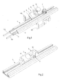
- Figure 1 shows a partially exploded view in perspective of a track and a lighting unit of a lighting system according to the present invention.
- Figure 2 shows a track and lighting unit of a lighting system according to the present invention in perspective.
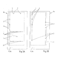
- Figures 3A and 3B show two possible arrangements of a lighting system in a dispensing apparatus according to the present invention.
- a lighting system according to the present invention comprises a track 1 and a lighting unit 2.
- the illustrated track 1 comprises an extruded aluminium profile 3, a plastic profile 4 inserted therein, carrying two embedded copper conductors 5A,5B.
- the cross section of the assembled track 1 is constant throughout its length.
- the lighting unit 2 comprises a housing 6, here made with half-shells 6A,6B, a connector 7 and, arranged alongside the connector 7, a mounting 8 to which a LED 9, a reflector 10 and a cover or lens 11 are mounted.
- one or more tracks 1 can be releasably interconnected to a track assembly, e.g. by providing the tracks 1 with mating connectors or using additional coupling blocks (not shown) for coupling at straight or variable angles.
- Several tracks 1 may be joined to form one branching juncture.
- Tracks, track adaptors, couplers and power supplies which have proven to be very well suited for use in a track assembly of a lighting system according to the invention are EUTRAC® 12V Low Voltage Low Profile Track system components, fabricated by EUTRAC, Germany.
- the mounting 8 of the lighting unit 2 further comprises a heat sink with cooling ribs 12 and a printed circuit board carrying electronics and a fixture for releasably mounting the LED 9 thereto.
- the LED fixture is connected to the heat sink 12 with a number of metal vias through the circuit board.
- the cooling ribs or fins of the heat sink 12 form, or protrude from, the rear surface of the mounting 8, facing away from the LED, providing maximum and unobstructed cooling to the LED 9. Further, as the heat is radiated away from the back of the mounting 8 in opposite direction to the light emission direction, direct heating of nearby illuminated objects is minimized.
- the mounting 8 is pivotably mounted to the housing 6, so that the lighting direction of the LED 9 may be adjusted relative thereto.
- the connector 7 is a rotating clamping connector, provided with a T-shaped coupling head with electrical contacts at its tips. For coupling, the T-head is inserted into the track 1 in parallel thereto. At a desired position, the connector 7 is rotated by a quarter turn to provide a mechanical clamping connection to the track 1 and to bring the tips of the T-head into electrical contact with the electrodes 6A,6B. In reverse manner the connector 7 may be removed from the track 1.
- the housing 6 is rotatable about the connector 7, so that the orientation of the lighting unit 2, in particular that of the mounting 8, with respect to the track 1 can be adjusted. Upon clamping the connector 7 to the track 1, the housing 6 is also clamped down to the track 1 so that the position and orientation of the lighting unit 2 are fixed.
- the housing is attached to the connector by means of clamping screws 13 (Fig. 2), or any other fixing technique.
- the mounting 8 is pivotable about one axis, and rotatable about an axis perpendicular thereto, illumination is possible in substantially all angles relative to the track.
- the units 2 are freely placeable along a track 1, being part of a modular track assembly, the lighting system provides substantially complete freedom to design and realise a desired lighting arrangement.
- a preferred LED 9 for use in the lighting system according to the present invention is a warm white light LED with a colour temperature of 4500 K or a bright white LED with a colour temperature of 6500 K, e.g. of the Philips® Luxeon® K2 series, which, especially in combination with a matching lens, provides an intense spot-light illumination pattern from the lighting unit.
- the LED 9 may also be a coloured LED or, e.g., a trio of red, green and blue single colour LEDs in combination yielding white light, the colour temperature of which may be varied by adjusting the relative light intensities of the individual LEDs.
- Figures 3A and 3B show a dispensing apparatus with a closed cabinet 14, provided with a lighting system according to the present invention.
- Several tracks 1 are constructed to a track assembly with a vertical stem and a number of branches, to which tracks a plurality of lighting units 2 is mounted.
- two different lighting arrangements each optimised for a different display within the apparatus are realised.
- the lighting system is provided with a DC power unit 15 and with a control unit 16 which transmits and receives signals as commands and digital information signals along one of the electrodes 5A,5B of the tracks 1.
- the signals comprise addressing information for selectively addressing and controlling individual lighting units 2.
- the electronics of the lighting units 2 are adapted to detect the signals superposed or modulated on the power line, and to recognise and process command signals marked with the appropriate address signal and to control the current through the LED or LEDs accordingly, e.g. for switching on/off or dimming the LED.
- status information on the power emitted from the LED is sent back by the lighting unit (2) to the control unit (16) for feedback and maintenance purposes.
- a lighting unit 2 may be replaced to any other position on the track assembly, or the track assembly may be reconfigured, without having to reprogram the dynamic lighting effect obtained from that lighting unit 2 if so desired.
- control unit is reprogrammable, so that one or several different lighting programs or dynamic lighting effects may be altered, stored and run, so that the same spatial arrangement of the display obtains a "fresh look", again attracting the attention of consumers which have may grown accustomed to the previously shown display.
- one or more lighting units 2 may be provided with a motor for pivoting the mounting 8 of the lighting unit 2 and control signals may be used for the operation of the motor, causing the according illuminated spot to move.
Landscapes
- Engineering & Computer Science (AREA)
- General Engineering & Computer Science (AREA)
- Physics & Mathematics (AREA)
- Microelectronics & Electronic Packaging (AREA)
- Optics & Photonics (AREA)
- Arrangement Of Elements, Cooling, Sealing, Or The Like Of Lighting Devices (AREA)
- Control Of Vending Devices And Auxiliary Devices For Vending Devices (AREA)
- Non-Portable Lighting Devices Or Systems Thereof (AREA)
Priority Applications (7)
| Application Number | Priority Date | Filing Date | Title |
|---|---|---|---|
| EP06116675A EP1876389A1 (de) | 2006-07-05 | 2006-07-05 | Beleuchtungssystem für Anzeigegerät |
| PCT/EP2007/056774 WO2008003725A1 (en) | 2006-07-05 | 2007-07-04 | Lighting system for a display apparatus |
| US12/307,216 US20090310362A1 (en) | 2006-07-05 | 2007-07-04 | Lighting system for a display apparatus |
| AU2007271125A AU2007271125A1 (en) | 2006-07-05 | 2007-07-04 | Lighting system for a display apparatus |
| CN200780025516XA CN101952651A (zh) | 2006-07-05 | 2007-07-04 | 用于展示设备的照明系统 |
| JP2009517265A JP2010512612A (ja) | 2006-07-05 | 2007-07-04 | ディスプレイ装置のための照明システム |
| EP07787070A EP2038579A1 (de) | 2006-07-05 | 2007-07-04 | Beleuchtungssystem für anzeigevorrichtung |
Applications Claiming Priority (1)
| Application Number | Priority Date | Filing Date | Title |
|---|---|---|---|
| EP06116675A EP1876389A1 (de) | 2006-07-05 | 2006-07-05 | Beleuchtungssystem für Anzeigegerät |
Publications (1)
| Publication Number | Publication Date |
|---|---|
| EP1876389A1 true EP1876389A1 (de) | 2008-01-09 |
Family
ID=37325454
Family Applications (2)
| Application Number | Title | Priority Date | Filing Date |
|---|---|---|---|
| EP06116675A Withdrawn EP1876389A1 (de) | 2006-07-05 | 2006-07-05 | Beleuchtungssystem für Anzeigegerät |
| EP07787070A Withdrawn EP2038579A1 (de) | 2006-07-05 | 2007-07-04 | Beleuchtungssystem für anzeigevorrichtung |
Family Applications After (1)
| Application Number | Title | Priority Date | Filing Date |
|---|---|---|---|
| EP07787070A Withdrawn EP2038579A1 (de) | 2006-07-05 | 2007-07-04 | Beleuchtungssystem für anzeigevorrichtung |
Country Status (6)
| Country | Link |
|---|---|
| US (1) | US20090310362A1 (de) |
| EP (2) | EP1876389A1 (de) |
| JP (1) | JP2010512612A (de) |
| CN (1) | CN101952651A (de) |
| AU (1) | AU2007271125A1 (de) |
| WO (1) | WO2008003725A1 (de) |
Cited By (7)
| Publication number | Priority date | Publication date | Assignee | Title |
|---|---|---|---|---|
| WO2009089868A1 (de) * | 2008-01-19 | 2009-07-23 | Glasbau Hahn Gmbh | Beleuchtungseinrichtung für eine vitrine |
| EP2110057A1 (de) * | 2008-04-18 | 2009-10-21 | Sarno Display S.r.l. - Socio Unico | Modulare Beleuchtungsvorrichtung mit niedriger Spannung für Verkaufsflächen |
| ITMI20090064A1 (it) * | 2009-01-22 | 2010-07-23 | Damian S R L | Macchina distributrice automatica di prodotti |
| WO2010099038A3 (en) * | 2009-02-27 | 2010-12-23 | Electrolux Home Products, Inc. | Front-to-back showcase lighting for a refrigerator |
| CH701348A1 (fr) * | 2009-06-24 | 2010-12-31 | Cyril Pilet | Systeme d'eclairage bijoux a sources lumineuses mobiles. |
| WO2011009783A3 (de) * | 2009-07-21 | 2011-04-21 | BSH Bosch und Siemens Hausgeräte GmbH | Haushaltsgerät mit verstellbarer innenraumleuchte |
| DK178014B1 (en) * | 2014-01-10 | 2015-03-09 | Led Ibond Holding Aps | Construction element with at least one electronic component |
Families Citing this family (15)
| Publication number | Priority date | Publication date | Assignee | Title |
|---|---|---|---|---|
| WO2008099305A1 (en) * | 2007-02-12 | 2008-08-21 | Philips Intellectual Property & Standards Gmbh | Control module for a lighting system, lighting system and light module for a lighting system |
| US7854616B2 (en) | 2007-10-12 | 2010-12-21 | The L.D. Kichler Co. | Positionable lighting systems and methods |
| US8166872B2 (en) * | 2008-03-12 | 2012-05-01 | Whirlpool Corporation | Modified atmosphere for food preservation |
| US8651711B2 (en) | 2009-02-02 | 2014-02-18 | Apex Technologies, Inc. | Modular lighting system and method employing loosely constrained magnetic structures |
| CN101825265B (zh) * | 2010-02-07 | 2012-12-26 | 鹤山丽得电子实业有限公司 | 一种led轨道灯 |
| TWI408461B (zh) * | 2010-05-18 | 2013-09-11 | Young Lighting Technology Corp | 背光模組 |
| DE112011104392B4 (de) | 2010-12-15 | 2019-03-28 | Molex Inc. | Energie aufnehmendes Bauelement und Anordnung mit diesem |
| US8858051B2 (en) * | 2011-09-14 | 2014-10-14 | Crs Electronics | LED track lighting having an illuminated track |
| WO2016024250A1 (es) * | 2014-08-14 | 2016-02-18 | Quiñones Vazquez Flavia Cecilia | Sistema de iluminacion para superficies de vidrio |
| CN104253347B (zh) * | 2014-09-23 | 2016-09-14 | 上海新蕊光电科技有限公司 | 一种连接器 |
| CN104848110A (zh) * | 2015-05-20 | 2015-08-19 | 江苏信合众泰精密机械有限公司 | 机床照明装置 |
| DE102016107147B4 (de) * | 2016-04-18 | 2017-11-30 | Rittal Gmbh & Co. Kg | Schaltschrankleuchte mit verstellbarer Leuchtmittelplatine |
| CN110553191B (zh) * | 2019-10-14 | 2024-03-22 | 江苏优为视界科技有限公司 | 一种基础照明和重点照明的组合式灯具 |
| CN212408294U (zh) * | 2020-01-07 | 2021-01-26 | 深圳市零奔洋光电股份有限公司 | 一种便捷安装的led灯箱模组 |
| MX2020006938A (es) * | 2020-07-13 | 2022-01-14 | Flavia Cecilia Quinones Vazquez | Dispositivo modular de iluminacion. |
Citations (9)
| Publication number | Priority date | Publication date | Assignee | Title |
|---|---|---|---|---|
| US3295093A (en) * | 1963-05-21 | 1966-12-27 | Lightolier Inc | Electric power distribution conduit accessible for connection thereto along substantially its entire length |
| WO1993010591A1 (en) * | 1991-11-13 | 1993-05-27 | Heikki Korkala | Intelligent lamp or intelligent contact terminal for a lamp |
| US6135615A (en) * | 1999-04-28 | 2000-10-24 | Lee; Cheng-Ping | Lamp suspension track assembly |
| US20020024812A1 (en) * | 2000-07-28 | 2002-02-28 | Agro James V. | Pivot mechanism for a light fixture |
| US20020176259A1 (en) * | 1999-11-18 | 2002-11-28 | Ducharme Alfred D. | Systems and methods for converting illumination |
| US20030137828A1 (en) * | 2002-01-10 | 2003-07-24 | Artak Ter-Hovhannisian | Low temperature led lighting system |
| US20050254262A1 (en) * | 2004-05-13 | 2005-11-17 | Chiu Hwa J | Track lamp assembly and display with the track lamp assembly |
| US20060083012A1 (en) * | 2004-10-18 | 2006-04-20 | Artak Ter-Hovhannissian | Vehicle and trailer lighting system |
| WO2006102888A1 (de) * | 2005-04-01 | 2006-10-05 | Christian Neubauer | Stromschiene für einen elektrischen verbraucher sowie beleuchtungseinrichtung |
Family Cites Families (12)
| Publication number | Priority date | Publication date | Assignee | Title |
|---|---|---|---|---|
| US2198096A (en) * | 1936-07-24 | 1940-04-23 | Arthur J Sweet | Portable lamp |
| JPS5634256A (en) * | 1979-08-29 | 1981-04-06 | Fuji Electric Co Ltd | Data transmission system |
| US4914431A (en) * | 1984-11-16 | 1990-04-03 | Severson Frederick E | Electronic control system for model railroads |
| US4689726A (en) * | 1986-02-28 | 1987-08-25 | Kretzschmar Thomas E | Lighting mechanism |
| US4979081A (en) * | 1989-12-07 | 1990-12-18 | Courtney Pope Lighting Limited | Electrical supply system |
| JPH07273695A (ja) * | 1994-01-24 | 1995-10-20 | Yair Maryanka | 直流導線を介する音声、音楽、映像、データの伝送 |
| US6175342B1 (en) * | 1996-04-15 | 2001-01-16 | Aadco, Inc. | Enhanced modular message board |
| US6550269B2 (en) * | 2000-02-16 | 2003-04-22 | The Coca-Cola Company | Dispensing apparatus with directional LED lighting |
| GB2370103B (en) * | 2000-12-14 | 2004-11-10 | P L M Illumination Ltd | LED lighting unit |
| JP2004344507A (ja) * | 2003-05-23 | 2004-12-09 | Yasuo Maki | 棚柱と棚受け金物に12vを主とする低い電圧の電気を直接流して活用 |
| US6999318B2 (en) * | 2003-07-28 | 2006-02-14 | Honeywell International Inc. | Heatsinking electronic devices |
| DE102004042854A1 (de) | 2004-08-18 | 2006-02-23 | Aldi Einkauf Gmbh & Co. Ohg | Warenpräsentationsbehälter, insbesondere Kühltheke |
-
2006
- 2006-07-05 EP EP06116675A patent/EP1876389A1/de not_active Withdrawn
-
2007
- 2007-07-04 US US12/307,216 patent/US20090310362A1/en not_active Abandoned
- 2007-07-04 AU AU2007271125A patent/AU2007271125A1/en not_active Abandoned
- 2007-07-04 EP EP07787070A patent/EP2038579A1/de not_active Withdrawn
- 2007-07-04 CN CN200780025516XA patent/CN101952651A/zh active Pending
- 2007-07-04 JP JP2009517265A patent/JP2010512612A/ja active Pending
- 2007-07-04 WO PCT/EP2007/056774 patent/WO2008003725A1/en not_active Ceased
Patent Citations (9)
| Publication number | Priority date | Publication date | Assignee | Title |
|---|---|---|---|---|
| US3295093A (en) * | 1963-05-21 | 1966-12-27 | Lightolier Inc | Electric power distribution conduit accessible for connection thereto along substantially its entire length |
| WO1993010591A1 (en) * | 1991-11-13 | 1993-05-27 | Heikki Korkala | Intelligent lamp or intelligent contact terminal for a lamp |
| US6135615A (en) * | 1999-04-28 | 2000-10-24 | Lee; Cheng-Ping | Lamp suspension track assembly |
| US20020176259A1 (en) * | 1999-11-18 | 2002-11-28 | Ducharme Alfred D. | Systems and methods for converting illumination |
| US20020024812A1 (en) * | 2000-07-28 | 2002-02-28 | Agro James V. | Pivot mechanism for a light fixture |
| US20030137828A1 (en) * | 2002-01-10 | 2003-07-24 | Artak Ter-Hovhannisian | Low temperature led lighting system |
| US20050254262A1 (en) * | 2004-05-13 | 2005-11-17 | Chiu Hwa J | Track lamp assembly and display with the track lamp assembly |
| US20060083012A1 (en) * | 2004-10-18 | 2006-04-20 | Artak Ter-Hovhannissian | Vehicle and trailer lighting system |
| WO2006102888A1 (de) * | 2005-04-01 | 2006-10-05 | Christian Neubauer | Stromschiene für einen elektrischen verbraucher sowie beleuchtungseinrichtung |
Cited By (12)
| Publication number | Priority date | Publication date | Assignee | Title |
|---|---|---|---|---|
| WO2009089868A1 (de) * | 2008-01-19 | 2009-07-23 | Glasbau Hahn Gmbh | Beleuchtungseinrichtung für eine vitrine |
| EP2110057A1 (de) * | 2008-04-18 | 2009-10-21 | Sarno Display S.r.l. - Socio Unico | Modulare Beleuchtungsvorrichtung mit niedriger Spannung für Verkaufsflächen |
| ITMI20090064A1 (it) * | 2009-01-22 | 2010-07-23 | Damian S R L | Macchina distributrice automatica di prodotti |
| WO2010099038A3 (en) * | 2009-02-27 | 2010-12-23 | Electrolux Home Products, Inc. | Front-to-back showcase lighting for a refrigerator |
| US8186844B2 (en) | 2009-02-27 | 2012-05-29 | Electrolux Home Products, Inc. | Front-to-back showcase lighting for a refrigerator |
| CH701348A1 (fr) * | 2009-06-24 | 2010-12-31 | Cyril Pilet | Systeme d'eclairage bijoux a sources lumineuses mobiles. |
| WO2011009783A3 (de) * | 2009-07-21 | 2011-04-21 | BSH Bosch und Siemens Hausgeräte GmbH | Haushaltsgerät mit verstellbarer innenraumleuchte |
| DK178014B1 (en) * | 2014-01-10 | 2015-03-09 | Led Ibond Holding Aps | Construction element with at least one electronic component |
| WO2015104024A1 (en) * | 2014-01-10 | 2015-07-16 | Led Ibond Holding Aps | Construction element with at least one electronic component and associated method |
| US9587812B2 (en) | 2014-01-10 | 2017-03-07 | Led Ibond International Aps | Construction element with at least one electronic component and associated method |
| US9874339B2 (en) | 2014-01-10 | 2018-01-23 | Led Ibond International Aps | Construction element with at least one electronic component and associated method |
| RU2664952C2 (ru) * | 2014-01-10 | 2018-08-23 | ЛЭД айБОНД ИНТЕРНЕШНЛ АпС | Конструкционный элемент с по меньшей мере одним электронным компонентом и связанный с ним способ |
Also Published As
| Publication number | Publication date |
|---|---|
| JP2010512612A (ja) | 2010-04-22 |
| EP2038579A1 (de) | 2009-03-25 |
| CN101952651A (zh) | 2011-01-19 |
| AU2007271125A1 (en) | 2008-01-10 |
| WO2008003725A1 (en) | 2008-01-10 |
| US20090310362A1 (en) | 2009-12-17 |
Similar Documents
| Publication | Publication Date | Title |
|---|---|---|
| US20090310362A1 (en) | Lighting system for a display apparatus | |
| CN101506574B (zh) | 包含可调节光模块的照明设备 | |
| US9326347B2 (en) | Light fixture with background display using diffuse pixels between nondiffuse light sources | |
| US8235539B2 (en) | Elongated LED lighting fixture | |
| CN102844613B (zh) | 具有突出的漫射盖罩和多个光源的摇头灯具 | |
| US10337699B2 (en) | Light | |
| US9523469B2 (en) | Lighting system for cabinet display case | |
| US20080089060A1 (en) | Methods and apparatus for improving versatility and impact resistance of lighting fixtures | |
| US20140056010A1 (en) | Modular lamp controller | |
| CN104279457A (zh) | 包含多个远程可定位的发光模块的剧场灯 | |
| US10948173B2 (en) | Luminaire, housing component for a luminaire and method for producing a luminaire | |
| CN102782398A (zh) | 用于传统街道照明系统的高效照明系统 | |
| US10959313B2 (en) | LED lighting incorporating DMX communication | |
| KR20100133460A (ko) | 일체형 조명 시스템을 구비한 전자 디스플레이 장치 | |
| EP4526590A1 (de) | Linsenanordnung für eine beleuchtungsvorrichtung | |
| KR101739914B1 (ko) | 천장설치용 라인타입 조명기구 | |
| WO2004100611A1 (en) | Led lighting module and system | |
| TW200842279A (en) | Modular lighting device and lighting arrangement | |
| US10935224B2 (en) | LED lighting incorporating DMX communication | |
| KR101003778B1 (ko) | 다기능의 발광 다이오드 조명 장치 및 그의 처리 방법 | |
| JP2016058171A (ja) | Led照明器具 | |
| KR101853194B1 (ko) | 모듈형 조명장치 | |
| KR200425784Y1 (ko) | 진열장용 조명장치 | |
| CN214840334U (zh) | 一种电流自适应型调光灯具 | |
| KR20170027287A (ko) | 전구형 벌브 |
Legal Events
| Date | Code | Title | Description |
|---|---|---|---|
| PUAI | Public reference made under article 153(3) epc to a published international application that has entered the european phase |
Free format text: ORIGINAL CODE: 0009012 |
|
| AK | Designated contracting states |
Kind code of ref document: A1 Designated state(s): AT BE BG CH CY CZ DE DK EE ES FI FR GB GR HU IE IS IT LI LT LU LV MC NL PL PT RO SE SI SK TR |
|
| AX | Request for extension of the european patent |
Extension state: AL BA HR MK YU |
|
| AKX | Designation fees paid | ||
| REG | Reference to a national code |
Ref country code: DE Ref legal event code: 8566 |
|
| STAA | Information on the status of an ep patent application or granted ep patent |
Free format text: STATUS: THE APPLICATION IS DEEMED TO BE WITHDRAWN |
|
| 18D | Application deemed to be withdrawn |
Effective date: 20080710 |