EP1876408A2 - Vorrichtung zur Freigabe des Speerschaftes eines Harpunengeschützes für Gerätetaucher - Google Patents
Vorrichtung zur Freigabe des Speerschaftes eines Harpunengeschützes für Gerätetaucher Download PDFInfo
- Publication number
- EP1876408A2 EP1876408A2 EP07111468A EP07111468A EP1876408A2 EP 1876408 A2 EP1876408 A2 EP 1876408A2 EP 07111468 A EP07111468 A EP 07111468A EP 07111468 A EP07111468 A EP 07111468A EP 1876408 A2 EP1876408 A2 EP 1876408A2
- Authority
- EP
- European Patent Office
- Prior art keywords
- lever
- trigger
- shaft
- gun
- spear
- Prior art date
- Legal status (The legal status is an assumption and is not a legal conclusion. Google has not performed a legal analysis and makes no representation as to the accuracy of the status listed.)
- Granted
Links
Images


Classifications
-
- F—MECHANICAL ENGINEERING; LIGHTING; HEATING; WEAPONS; BLASTING
- F41—WEAPONS
- F41B—WEAPONS FOR PROJECTING MISSILES WITHOUT USE OF EXPLOSIVE OR COMBUSTIBLE PROPELLANT CHARGE; WEAPONS NOT OTHERWISE PROVIDED FOR
- F41B7/00—Spring guns
- F41B7/04—Spring guns adapted to discharge harpoons
- F41B7/043—Accessories therefor
- F41B7/046—Trigger mechanisms therefor
-
- A—HUMAN NECESSITIES
- A01—AGRICULTURE; FORESTRY; ANIMAL HUSBANDRY; HUNTING; TRAPPING; FISHING
- A01K—ANIMAL HUSBANDRY; AVICULTURE; APICULTURE; PISCICULTURE; FISHING; REARING OR BREEDING ANIMALS, NOT OTHERWISE PROVIDED FOR; NEW BREEDS OF ANIMALS
- A01K81/00—Fishing with projectiles
Definitions
- the present invention relates generally to the field of equipment for underwater activities and more specifically to the field of spear guns for fishing and underwater hunting.
- the invention relates to a device for releasing the spear shaft of a fishing gun for scuba divers.
- a gun of this type comprises a frame comprising a longitudinally elongated body fitted at the rear end with a grip and a trigger that is pulled to eject a spear attached to the front end of a shaft mounted slidingly on the elongated body of said frame.
- the rear end of the shaft is connected to a string line for the retrieval of the spear and any prey caught by the diver.
- the propulsive force of the spear is provided by a pair of cables made of an elastic material that are stretched and hooked onto the shaft of the spear when the diver loads the gun, then the spear is released when the trigger is pulled, converting the elastic energy accumulated by the elastic cables into kinetic energy in the spear shaft.
- the kinematic mechanism that enables the diver to shoot the spear by means of the trigger generally comprises a lever hinged onto the frame and presenting a latch element at one end that engages in a notch at the proximal end of the spear shaft when the spear on the gun is loaded so as to withstand the pulling force exerted on the shaft by the elastic cables.
- the proximal end of its shaft abuts against a radial appendage on the lever, thereby inducing its rotation, as a result of which, in addition to the latch element engaging in the notch on the shaft, the opposite end of the lever elastically engages within a seat in the trigger formed on the side opposite its operating arm.
- the kinematic chains used to operate them do not allow for any adjustment of the stroke of the trigger and of the effort needed to pull it.
- the spear may be released by accident if the stroke of the trigger is short.
- the problem of graduating the effort required to pull the trigger and/or adjusting the trigger's stroke is strongly felt and has yet to find a simple and safe solution.
- the object of the present invention is to provide a device for releasing the spear shaft of a fishing gun for scuba divers wherein the effort required to pull the trigger and/or the operating stroke of the trigger can be graduated according to a given diver's needs and features.
- a particular object of the invention is to provide a device of the aforementioned type wherein the force required to pull the trigger and/or the trigger's stroke can be adjusted quickly and easily by means of a kinematic chain that is not particularly complex from the point of view of its manufacture and assembly.
- a device for releasing the spear shaft of a fishing gun for scuba divers wherein the latch element is formed on a first lever, the front end of which is pivotally connected to a threaded stem fixedly attached to the frame of the gun and lying parallel to its longitudinal axis and elastic means are provided for keeping the first lever in a resting position, corresponding to the situation when the gun is not loaded, wherein the latch element abuts against a first shoulder integrally attached to the frame and is axially aligned with the spear shaft when it is prepared for loading on the elongated body of the frame.
- the trigger comprises an elastically-tensioned abutment portion for the front end of the first lever and extending forward from a convex upper surface intersecting a concave surface at an edge that traces a first circular trajectory as the trigger is rotated.
- a second lever pivotally connected to the frame at a point situated behind the latch element and below the front end of the first lever is also provided, the front end of the second lever being movable along a second circular trajectory intersecting the first circular trajectory.
- An arm of the second lever extends to intersect the trajectory of the spear shaft when the gun is loaded, whereby during the axial movement to load the spear, the spear shaft abuts against the latch element first, displacing the first lever from its resting position and occupying a loaded position wherein the latch element engages in the shaped recess in the shaft, and then it abuts against the arm of the second lever, making the latter rotate until it abuts against the first lever on at the latch element, simultaneously bringing its front end up against the convex surface of the trigger.
- the front end of the first lever is slidingly connected to the threaded stem, whereby the first lever is adjustably displaceable in the longitudinal axis direction to enable a variation in the point where the first lever rests on the second lever and the consequent force with which the front end of the second lever rests against the convex surface of the trigger.
- the adjectives "front” and “rear” refer to the orientation of the gun and refer to the left and right ends, respectively, as the spear gun appears in the figures.
- the adjectives "upper” and “lower” are used in an absolute sense and refer to the axis of longitudinal symmetry of the gun: the shaft and spear point are placed in the upper part of the gun, i.e. above its axis of symmetry, while the trigger is conventionally positioned in the lower part of the gun.
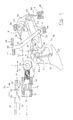
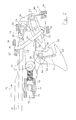
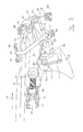
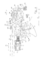
- the illustration of the fishing gun for scuba divers is restricted to the elements comprising the release device according to the invention.
- the swivel pins for the articulation of the various component parts and the abutment elements for the moving parts are consequently only shown schematically, said pins and abutment elements being integrally attached to the gun frame, which is not shown in its entirety because it is structurally well-known to a person skilled in the art.
- S1 and S2 are used to indicate a cross-sectional view of two bushes integrally attached to the gun frame;
- S4, S5, S6, S7 and S8 are abutment elements integrally attached to the gun frame, and are consequently fixed in position, their purpose being to contain the movements of the moving parts of the device, as explained later on.
- the movable elements of the device comprise a first lever L1, a second lever L2 and a trigger L3 articulated respectively around pins C1, C2 and C3, which are integrally attached to the frame.
- the lever L2 and the trigger L3 have a flattened shape and lie substantially in the vertical plane of symmetry of the gun, passing through its longitudinal axis X, while the lever L1 comprises two symmetrical elements (only one of them shown in the figures), lying parallel to the plane of symmetry of the gun, the distance between them corresponding to at least the thicknesses of the lever L2 and of the trigger L3 so that the latter two elements can move without interfering with the movement of the lever L1.
- the bushes S1 and S2 support a freely-revolving longitudinal threaded stem 10, the rear end of which (facing towards the right in the figure) is threaded inside and screws into a corresponding threaded hole in a transverse hub 11 from either side of which there project two transverse, symmetrical pins C1 (only one of which is shown in the figures) around which the two parallel and adjacent elements forming the first lever L1 are integrally articulated.
- the axis of the threaded stem 10 lies substantially along the vertical plane of symmetry of the gun. Between the two bushes S1 and S2, the threaded stem 10 is provided with ring-shaped ribbing 12, the knurled lateral surface of which extends from the bushes S1 and S2 and enables the scuba diver to turn the threaded stem 10, thereby screwing or unscrewing its end in the threaded hole in the hub 11 and consequently displacing the axial position of the transverse pin C1 in the two directions indicated by the double line F1.
- the pin C1 occupies its rearmost position, whereas in figure 6 the pin C1 is at the end of its forward stroke.
- the lever L1 is hinged around the pin C1 at its front end (on the left in the figure), whereas it is fitted at its rear end with a freely-revolving wheel 14.
- the upper side of the rear end of the lever L1 terminates with a surface 13 designed to be pushed up against a shoulder S6, which is integrally attached to the gun frame.
- the surface 13 and the shoulder S6 define the end of the stroke of the lever L1 in its leftward-turning angular displacement, corresponding to the resting position of the lever L1, when the gun is not loaded.
- the rear end of the second lever L2 is connected to the swivel pin C2, which is positioned to the rear of the wheel 14 and on a slightly lower level than the pin C1.
- the anticlockwise rotation of the second lever L2 is restricted by a shoulder S4.
- the pin C2 is wrapped with the turns of a spring M2, which terminate with two arms 15 and 16.
- the lower arm 15 is retained by a pair of fixed striker plates S5, while the upper arm 16 rests up against the wheel 14 of the lever L1, consequently pushing the surface 13 towards the shoulder S6.
- An upward-facing bracket 20 extends from the rear end of the second lever L2, the purpose of which will be explained with reference to the subsequent figures.
- the front of the trigger L3, revolving around the pin C3, has a front concave surface 51, on which the scuba diver's finger comes to bear, a cylindrical and convex surface 39, whose axis coincides with that of the pin C3, and an upper-rear concave circular surface 38 with a radius of curvature equal to the distance between the axis of the pin C2 and the front end 18 of the lever L2.
- the concave circular surface 39 overlaps the trajectory T2 traced by the end 18 of the lever L2 as it moves rightwards.
- the edge 40 common to the surfaces 38 and 39, which traces the trajectory T3, coincides with the point T, where the trajectories T2 and T3 intersect each other.
- a stem 24 is housed, with an angular slack, in a seat 41 in the lever L2, the upper end 25 of said stem being retained between striker plates S7 and S8.
- said stem 24 is withdrawn, i.e. it does not extend beyond the striker plates S7 and S8, whereas it does project therefrom when spear is loaded on the gun, as shown in figure 4.
- Said upper end 25 serves as a transmission element for a string line (not shown) that links the rear end of the spear shaft 30 to the frame of the gun by means of a hole 32 in the shaft to which one end of the line is attached.
- the shaft 30 is pushed along the gun in the direction of the arrow F2 so that its rear end 31 rests up against the wheel 14 of the lever L1, as shown in figure 2.
- the levers L1 and L2, the trigger L3, the stem 24 and the springs M2 and M3 are still in the positions shown in figure 1.
- the leftward axial tensile force coming to bear on the shaft 30 in its loaded position is transmitted via the surface 34 interfacing with the recess 33 to the wheel 14 and via its upper surface 50 to the lever L2.
- Said force generates an arm moment b1, balanced by the arm moment b2 generated by the force with which the end 18 of the lever L2 rests against the surface 39 of the trigger L3.
- the force needed to turn the trigger leftwards must consequently generate a torque capable of exceeding the one due to the force of friction at the point of contact between the end 18 of the lever L2 and the surface 39 of the trigger L3.
- the force R4 overcomes the force of friction existing at the point of contact between the end 18 of the lever L2 and the surface 39 of the trigger L3, enabling the anticlockwise rotation of the trigger L3 and releasing the lever L2 that also turns anticlockwise, due to the effect of the spring M2, until it abuts against the shoulder S4.
- the leftward displacement of the point of contact entails a clockwise angular displacement of the lever L3 so the angular displacement required for the trigger to release the shaft 30 also increases.
- R4 R1*f*b1*b3/(b2*b4), where the only variable is the arm b1, which increases when the hub 11 is shifted leftwards, as seen in the figure, i.e. towards the front end of the gun, when the threaded stem 10 is screwed into the threaded hole in the hub 11.
Landscapes
- Life Sciences & Earth Sciences (AREA)
- Environmental Sciences (AREA)
- Engineering & Computer Science (AREA)
- General Engineering & Computer Science (AREA)
- Marine Sciences & Fisheries (AREA)
- Animal Husbandry (AREA)
- Biodiversity & Conservation Biology (AREA)
- Toys (AREA)
- Fishing Rods (AREA)
- Underground Or Underwater Handling Of Building Materials (AREA)
Applications Claiming Priority (1)
| Application Number | Priority Date | Filing Date | Title |
|---|---|---|---|
| IT000172A ITFI20060172A1 (it) | 2006-07-05 | 2006-07-05 | Dispositivo di sgancio dell'asta dell'arpione di un fucile per pescatore subacqueo |
Publications (3)
| Publication Number | Publication Date |
|---|---|
| EP1876408A2 true EP1876408A2 (de) | 2008-01-09 |
| EP1876408A3 EP1876408A3 (de) | 2010-03-17 |
| EP1876408B1 EP1876408B1 (de) | 2011-08-31 |
Family
ID=38508911
Family Applications (1)
| Application Number | Title | Priority Date | Filing Date |
|---|---|---|---|
| EP07111468A Not-in-force EP1876408B1 (de) | 2006-07-05 | 2007-06-29 | Vorrichtung zur Freigabe des Speerschaftes eines Harpunengeschützes für Gerätetaucher |
Country Status (4)
| Country | Link |
|---|---|
| US (1) | US7726291B2 (de) |
| EP (1) | EP1876408B1 (de) |
| AT (1) | ATE522781T1 (de) |
| IT (1) | ITFI20060172A1 (de) |
Families Citing this family (7)
| Publication number | Priority date | Publication date | Assignee | Title |
|---|---|---|---|---|
| ITGE20070077A1 (it) * | 2007-08-08 | 2009-02-09 | Mares Spa | Fucile ad elastici per pesca subacquea. |
| US8091540B2 (en) * | 2007-09-07 | 2012-01-10 | Kodabow, Inc. | Crossbow |
| US20090194086A1 (en) * | 2008-01-17 | 2009-08-06 | Kempf James J | Shooting bow |
| US8651094B2 (en) * | 2010-01-19 | 2014-02-18 | Kodabow Inc. | Bow having improved limbs, trigger releases, safety mechanisms and/or dry fire mechanisms |
| US8899218B2 (en) | 2012-09-19 | 2014-12-02 | James J. Kempf | Shooting bow |
| CN203011235U (zh) * | 2012-12-28 | 2013-06-19 | 焦作市三利达娱乐设备有限公司 | 一种弩用双联动扳机系统 |
| US9255765B2 (en) * | 2014-01-17 | 2016-02-09 | Eric Nelson | Spear gun safety device |
Citations (1)
| Publication number | Priority date | Publication date | Assignee | Title |
|---|---|---|---|---|
| US5904132A (en) | 1996-10-10 | 1999-05-18 | The A B Biller Company | Spear fishing gun |
Family Cites Families (9)
| Publication number | Priority date | Publication date | Assignee | Title |
|---|---|---|---|---|
| FR2129212A5 (de) * | 1971-03-12 | 1972-10-27 | Azemard Jean | |
| FR2237167A1 (en) * | 1973-06-22 | 1975-02-07 | Beuchat Paul | Underwater crossbow trigger sensitivity adjustment - has cam acting as stop actuated by integral setting button |
| FR2272365A1 (en) * | 1974-05-24 | 1975-12-19 | Beuchat Sa | Trigger mechanism for underwater harpoon gun - has lug at end of harpoon freed from pocket between pivot arms when trigger pulled |
| US4192281A (en) * | 1977-06-10 | 1980-03-11 | King Fred V | Crossbow with trigger locking device |
| CA1188583A (en) * | 1984-04-17 | 1985-06-11 | Excalibur Crossbow Inc. | Crossbow trigger mechanism |
| US5649520A (en) * | 1995-01-25 | 1997-07-22 | Hunter's Manufacturing Co | Crossbow trigger mechanism |
| US6425386B1 (en) * | 2000-07-24 | 2002-07-30 | Daniel K. Adkins | Bowstring release system for crossbows |
| US6736123B1 (en) * | 2003-03-04 | 2004-05-18 | Gregory E. Summers | Crossbow trigger |
| US6802304B1 (en) * | 2004-01-20 | 2004-10-12 | Chu-Wei Chang | Trigger assembly with a safety device for a crossbow |
-
2006
- 2006-07-05 IT IT000172A patent/ITFI20060172A1/it unknown
-
2007
- 2007-06-29 EP EP07111468A patent/EP1876408B1/de not_active Not-in-force
- 2007-06-29 AT AT07111468T patent/ATE522781T1/de not_active IP Right Cessation
- 2007-07-05 US US11/825,418 patent/US7726291B2/en not_active Expired - Fee Related
Patent Citations (1)
| Publication number | Priority date | Publication date | Assignee | Title |
|---|---|---|---|---|
| US5904132A (en) | 1996-10-10 | 1999-05-18 | The A B Biller Company | Spear fishing gun |
Also Published As
| Publication number | Publication date |
|---|---|
| EP1876408A3 (de) | 2010-03-17 |
| US7726291B2 (en) | 2010-06-01 |
| ITFI20060172A1 (it) | 2008-01-06 |
| EP1876408B1 (de) | 2011-08-31 |
| US20080017177A1 (en) | 2008-01-24 |
| ATE522781T1 (de) | 2011-09-15 |
Similar Documents
| Publication | Publication Date | Title |
|---|---|---|
| EP1876408B1 (de) | Vorrichtung zur Freigabe des Speerschaftes eines Harpunengeschützes für Gerätetaucher | |
| US7748370B1 (en) | Method of cocking a crossbow having increased performance | |
| US9102379B2 (en) | Actuator device for a bicycle gearshift and nut for such a device | |
| US4574767A (en) | Bow trigger mechanism | |
| US4160437A (en) | Archery bow string release device | |
| US8899218B2 (en) | Shooting bow | |
| US9182190B2 (en) | Linear clutch for use with a bow and an arrow rest | |
| US9669527B2 (en) | Digital torque wrench | |
| KR102382907B1 (ko) | 보우스트링 해제기 | |
| US20190017774A1 (en) | Adjustable stock systems for firearms | |
| US8453632B2 (en) | Bowstring drawing and release assist apparatus and method thereof | |
| US9400160B1 (en) | Broad head arrow tip and associated methods | |
| CN107416118B (zh) | 自行车换档机构的致动器装置和相应的自行车换档机构 | |
| US20190099283A1 (en) | Joint brace with improved range of motion stop | |
| US9807988B2 (en) | Locking fishing reel seat | |
| US20170089663A1 (en) | Release aid for bow string | |
| US3952720A (en) | Bowstring release mechanism | |
| JP6968672B2 (ja) | 自転車のディレイラの制御ケーブルの作動装置 | |
| US20180229804A1 (en) | Front derailleur for a bicycle | |
| US1832727A (en) | Fish catching device | |
| NO811734L (no) | Anordning ved dregg. | |
| EP2072942B1 (de) | Unterwasserharpune mit elastischen Elementen | |
| EP3246241B1 (de) | Aktuatorvorrichtung für eine fahrradgangschaltung und entsprechende fahrradgangschaltung | |
| EP3457072B1 (de) | Abzugsvorrichtung in simulierter waffe | |
| EP3155350A1 (de) | Elektronische schnellstopp-deaktivierung |
Legal Events
| Date | Code | Title | Description |
|---|---|---|---|
| PUAI | Public reference made under article 153(3) epc to a published international application that has entered the european phase |
Free format text: ORIGINAL CODE: 0009012 |
|
| AK | Designated contracting states |
Kind code of ref document: A2 Designated state(s): AT BE BG CH CY CZ DE DK EE ES FI FR GB GR HU IE IS IT LI LT LU LV MC MT NL PL PT RO SE SI SK TR |
|
| AX | Request for extension of the european patent |
Extension state: AL BA HR MK YU |
|
| PUAL | Search report despatched |
Free format text: ORIGINAL CODE: 0009013 |
|
| AK | Designated contracting states |
Kind code of ref document: A3 Designated state(s): AT BE BG CH CY CZ DE DK EE ES FI FR GB GR HU IE IS IT LI LT LU LV MC MT NL PL PT RO SE SI SK TR |
|
| AX | Request for extension of the european patent |
Extension state: AL BA HR MK RS |
|
| 17P | Request for examination filed |
Effective date: 20100504 |
|
| 17Q | First examination report despatched |
Effective date: 20100614 |
|
| AKX | Designation fees paid |
Designated state(s): AT BE BG CH CY CZ DE DK EE ES FI FR GB GR HU IE IS IT LI LT LU LV MC MT NL PL PT RO SE SI SK TR |
|
| GRAP | Despatch of communication of intention to grant a patent |
Free format text: ORIGINAL CODE: EPIDOSNIGR1 |
|
| RIC1 | Information provided on ipc code assigned before grant |
Ipc: F41B 7/04 20060101AFI20110209BHEP |
|
| GRAC | Information related to communication of intention to grant a patent modified |
Free format text: ORIGINAL CODE: EPIDOSCIGR1 |
|
| GRAS | Grant fee paid |
Free format text: ORIGINAL CODE: EPIDOSNIGR3 |
|
| GRAA | (expected) grant |
Free format text: ORIGINAL CODE: 0009210 |
|
| AK | Designated contracting states |
Kind code of ref document: B1 Designated state(s): AT BE BG CH CY CZ DE DK EE ES FI FR GB GR HU IE IS IT LI LT LU LV MC MT NL PL PT RO SE SI SK TR |
|
| REG | Reference to a national code |
Ref country code: GB Ref legal event code: FG4D Ref country code: CH Ref legal event code: EP |
|
| REG | Reference to a national code |
Ref country code: IE Ref legal event code: FG4D |
|
| REG | Reference to a national code |
Ref country code: DE Ref legal event code: R096 Ref document number: 602007016696 Country of ref document: DE Effective date: 20111110 |
|
| REG | Reference to a national code |
Ref country code: NL Ref legal event code: VDEP Effective date: 20110831 |
|
| LTIE | Lt: invalidation of european patent or patent extension |
Effective date: 20110831 |
|
| PG25 | Lapsed in a contracting state [announced via postgrant information from national office to epo] |
Ref country code: FI Free format text: LAPSE BECAUSE OF FAILURE TO SUBMIT A TRANSLATION OF THE DESCRIPTION OR TO PAY THE FEE WITHIN THE PRESCRIBED TIME-LIMIT Effective date: 20110831 Ref country code: LT Free format text: LAPSE BECAUSE OF FAILURE TO SUBMIT A TRANSLATION OF THE DESCRIPTION OR TO PAY THE FEE WITHIN THE PRESCRIBED TIME-LIMIT Effective date: 20110831 Ref country code: NL Free format text: LAPSE BECAUSE OF FAILURE TO SUBMIT A TRANSLATION OF THE DESCRIPTION OR TO PAY THE FEE WITHIN THE PRESCRIBED TIME-LIMIT Effective date: 20110831 Ref country code: SE Free format text: LAPSE BECAUSE OF FAILURE TO SUBMIT A TRANSLATION OF THE DESCRIPTION OR TO PAY THE FEE WITHIN THE PRESCRIBED TIME-LIMIT Effective date: 20110831 Ref country code: IS Free format text: LAPSE BECAUSE OF FAILURE TO SUBMIT A TRANSLATION OF THE DESCRIPTION OR TO PAY THE FEE WITHIN THE PRESCRIBED TIME-LIMIT Effective date: 20111231 |
|
| REG | Reference to a national code |
Ref country code: AT Ref legal event code: MK05 Ref document number: 522781 Country of ref document: AT Kind code of ref document: T Effective date: 20110831 |
|
| PG25 | Lapsed in a contracting state [announced via postgrant information from national office to epo] |
Ref country code: SI Free format text: LAPSE BECAUSE OF FAILURE TO SUBMIT A TRANSLATION OF THE DESCRIPTION OR TO PAY THE FEE WITHIN THE PRESCRIBED TIME-LIMIT Effective date: 20110831 Ref country code: LV Free format text: LAPSE BECAUSE OF FAILURE TO SUBMIT A TRANSLATION OF THE DESCRIPTION OR TO PAY THE FEE WITHIN THE PRESCRIBED TIME-LIMIT Effective date: 20110831 Ref country code: GR Free format text: LAPSE BECAUSE OF FAILURE TO SUBMIT A TRANSLATION OF THE DESCRIPTION OR TO PAY THE FEE WITHIN THE PRESCRIBED TIME-LIMIT Effective date: 20111201 Ref country code: CY Free format text: LAPSE BECAUSE OF FAILURE TO SUBMIT A TRANSLATION OF THE DESCRIPTION OR TO PAY THE FEE WITHIN THE PRESCRIBED TIME-LIMIT Effective date: 20110831 Ref country code: AT Free format text: LAPSE BECAUSE OF FAILURE TO SUBMIT A TRANSLATION OF THE DESCRIPTION OR TO PAY THE FEE WITHIN THE PRESCRIBED TIME-LIMIT Effective date: 20110831 |
|
| PG25 | Lapsed in a contracting state [announced via postgrant information from national office to epo] |
Ref country code: BE Free format text: LAPSE BECAUSE OF FAILURE TO SUBMIT A TRANSLATION OF THE DESCRIPTION OR TO PAY THE FEE WITHIN THE PRESCRIBED TIME-LIMIT Effective date: 20110831 |
|
| PG25 | Lapsed in a contracting state [announced via postgrant information from national office to epo] |
Ref country code: SK Free format text: LAPSE BECAUSE OF FAILURE TO SUBMIT A TRANSLATION OF THE DESCRIPTION OR TO PAY THE FEE WITHIN THE PRESCRIBED TIME-LIMIT Effective date: 20110831 Ref country code: CZ Free format text: LAPSE BECAUSE OF FAILURE TO SUBMIT A TRANSLATION OF THE DESCRIPTION OR TO PAY THE FEE WITHIN THE PRESCRIBED TIME-LIMIT Effective date: 20110831 |
|
| PG25 | Lapsed in a contracting state [announced via postgrant information from national office to epo] |
Ref country code: PT Free format text: LAPSE BECAUSE OF FAILURE TO SUBMIT A TRANSLATION OF THE DESCRIPTION OR TO PAY THE FEE WITHIN THE PRESCRIBED TIME-LIMIT Effective date: 20120102 Ref country code: EE Free format text: LAPSE BECAUSE OF FAILURE TO SUBMIT A TRANSLATION OF THE DESCRIPTION OR TO PAY THE FEE WITHIN THE PRESCRIBED TIME-LIMIT Effective date: 20110831 Ref country code: RO Free format text: LAPSE BECAUSE OF FAILURE TO SUBMIT A TRANSLATION OF THE DESCRIPTION OR TO PAY THE FEE WITHIN THE PRESCRIBED TIME-LIMIT Effective date: 20110831 Ref country code: PL Free format text: LAPSE BECAUSE OF FAILURE TO SUBMIT A TRANSLATION OF THE DESCRIPTION OR TO PAY THE FEE WITHIN THE PRESCRIBED TIME-LIMIT Effective date: 20110831 |
|
| PG25 | Lapsed in a contracting state [announced via postgrant information from national office to epo] |
Ref country code: DK Free format text: LAPSE BECAUSE OF FAILURE TO SUBMIT A TRANSLATION OF THE DESCRIPTION OR TO PAY THE FEE WITHIN THE PRESCRIBED TIME-LIMIT Effective date: 20110831 |
|
| PLBE | No opposition filed within time limit |
Free format text: ORIGINAL CODE: 0009261 |
|
| STAA | Information on the status of an ep patent application or granted ep patent |
Free format text: STATUS: NO OPPOSITION FILED WITHIN TIME LIMIT |
|
| 26N | No opposition filed |
Effective date: 20120601 |
|
| PGFP | Annual fee paid to national office [announced via postgrant information from national office to epo] |
Ref country code: GB Payment date: 20120622 Year of fee payment: 6 |
|
| REG | Reference to a national code |
Ref country code: DE Ref legal event code: R097 Ref document number: 602007016696 Country of ref document: DE Effective date: 20120601 |
|
| PG25 | Lapsed in a contracting state [announced via postgrant information from national office to epo] |
Ref country code: MC Free format text: LAPSE BECAUSE OF NON-PAYMENT OF DUE FEES Effective date: 20120630 |
|
| REG | Reference to a national code |
Ref country code: CH Ref legal event code: PL |
|
| REG | Reference to a national code |
Ref country code: CH Ref legal event code: PL |
|
| REG | Reference to a national code |
Ref country code: IE Ref legal event code: MM4A |
|
| REG | Reference to a national code |
Ref country code: DE Ref legal event code: R119 Ref document number: 602007016696 Country of ref document: DE Effective date: 20130101 |
|
| PG25 | Lapsed in a contracting state [announced via postgrant information from national office to epo] |
Ref country code: LI Free format text: LAPSE BECAUSE OF NON-PAYMENT OF DUE FEES Effective date: 20120630 Ref country code: CH Free format text: LAPSE BECAUSE OF NON-PAYMENT OF DUE FEES Effective date: 20120630 Ref country code: DE Free format text: LAPSE BECAUSE OF NON-PAYMENT OF DUE FEES Effective date: 20130101 Ref country code: IE Free format text: LAPSE BECAUSE OF NON-PAYMENT OF DUE FEES Effective date: 20120629 |
|
| PG25 | Lapsed in a contracting state [announced via postgrant information from national office to epo] |
Ref country code: BG Free format text: LAPSE BECAUSE OF FAILURE TO SUBMIT A TRANSLATION OF THE DESCRIPTION OR TO PAY THE FEE WITHIN THE PRESCRIBED TIME-LIMIT Effective date: 20111130 |
|
| PG25 | Lapsed in a contracting state [announced via postgrant information from national office to epo] |
Ref country code: MT Free format text: LAPSE BECAUSE OF NON-PAYMENT OF DUE FEES Effective date: 20120630 |
|
| PG25 | Lapsed in a contracting state [announced via postgrant information from national office to epo] |
Ref country code: ES Free format text: LAPSE BECAUSE OF FAILURE TO SUBMIT A TRANSLATION OF THE DESCRIPTION OR TO PAY THE FEE WITHIN THE PRESCRIBED TIME-LIMIT Effective date: 20111211 |
|
| GBPC | Gb: european patent ceased through non-payment of renewal fee |
Effective date: 20130629 |
|
| PG25 | Lapsed in a contracting state [announced via postgrant information from national office to epo] |
Ref country code: GB Free format text: LAPSE BECAUSE OF NON-PAYMENT OF DUE FEES Effective date: 20130629 Ref country code: TR Free format text: LAPSE BECAUSE OF FAILURE TO SUBMIT A TRANSLATION OF THE DESCRIPTION OR TO PAY THE FEE WITHIN THE PRESCRIBED TIME-LIMIT Effective date: 20110831 |
|
| PG25 | Lapsed in a contracting state [announced via postgrant information from national office to epo] |
Ref country code: LU Free format text: LAPSE BECAUSE OF NON-PAYMENT OF DUE FEES Effective date: 20120629 |
|
| PG25 | Lapsed in a contracting state [announced via postgrant information from national office to epo] |
Ref country code: HU Free format text: LAPSE BECAUSE OF FAILURE TO SUBMIT A TRANSLATION OF THE DESCRIPTION OR TO PAY THE FEE WITHIN THE PRESCRIBED TIME-LIMIT Effective date: 20070629 |
|
| REG | Reference to a national code |
Ref country code: FR Ref legal event code: PLFP Year of fee payment: 10 |
|
| REG | Reference to a national code |
Ref country code: FR Ref legal event code: PLFP Year of fee payment: 11 |
|
| REG | Reference to a national code |
Ref country code: FR Ref legal event code: PLFP Year of fee payment: 12 |
|
| PGFP | Annual fee paid to national office [announced via postgrant information from national office to epo] |
Ref country code: FR Payment date: 20210622 Year of fee payment: 15 Ref country code: IT Payment date: 20210607 Year of fee payment: 15 |
|
| PG25 | Lapsed in a contracting state [announced via postgrant information from national office to epo] |
Ref country code: FR Free format text: LAPSE BECAUSE OF NON-PAYMENT OF DUE FEES Effective date: 20220630 |
|
| PG25 | Lapsed in a contracting state [announced via postgrant information from national office to epo] |
Ref country code: IT Free format text: LAPSE BECAUSE OF NON-PAYMENT OF DUE FEES Effective date: 20220629 |