EP1876504B1 - Aktiver Greifer für haptische Vorrichtungen - Google Patents
Aktiver Greifer für haptische Vorrichtungen Download PDFInfo
- Publication number
- EP1876504B1 EP1876504B1 EP06013754A EP06013754A EP1876504B1 EP 1876504 B1 EP1876504 B1 EP 1876504B1 EP 06013754 A EP06013754 A EP 06013754A EP 06013754 A EP06013754 A EP 06013754A EP 1876504 B1 EP1876504 B1 EP 1876504B1
- Authority
- EP
- European Patent Office
- Prior art keywords
- hand
- contact surface
- haptic device
- freedom
- user
- Prior art date
- Legal status (The legal status is an assumption and is not a legal conclusion. Google has not performed a legal analysis and makes no representation as to the accuracy of the status listed.)
- Active
Links
Images



Classifications
-
- G—PHYSICS
- G06—COMPUTING OR CALCULATING; COUNTING
- G06F—ELECTRIC DIGITAL DATA PROCESSING
- G06F3/00—Input arrangements for transferring data to be processed into a form capable of being handled by the computer; Output arrangements for transferring data from processing unit to output unit, e.g. interface arrangements
- G06F3/01—Input arrangements or combined input and output arrangements for interaction between user and computer
- G06F3/03—Arrangements for converting the position or the displacement of a member into a coded form
- G06F3/041—Digitisers, e.g. for touch screens or touch pads, characterised by the transducing means
- G06F3/045—Digitisers, e.g. for touch screens or touch pads, characterised by the transducing means using resistive elements, e.g. a single continuous surface or two parallel surfaces put in contact
-
- B—PERFORMING OPERATIONS; TRANSPORTING
- B25—HAND TOOLS; PORTABLE POWER-DRIVEN TOOLS; MANIPULATORS
- B25J—MANIPULATORS; CHAMBERS PROVIDED WITH MANIPULATION DEVICES
- B25J13/00—Controls for manipulators
- B25J13/02—Hand grip control means
-
- B—PERFORMING OPERATIONS; TRANSPORTING
- B25—HAND TOOLS; PORTABLE POWER-DRIVEN TOOLS; MANIPULATORS
- B25J—MANIPULATORS; CHAMBERS PROVIDED WITH MANIPULATION DEVICES
- B25J17/00—Joints
- B25J17/02—Wrist joints
- B25J17/0258—Two-dimensional joints
- B25J17/0266—Two-dimensional joints comprising more than two actuating or connecting rods
-
- G—PHYSICS
- G05—CONTROLLING; REGULATING
- G05G—CONTROL DEVICES OR SYSTEMS INSOFAR AS CHARACTERISED BY MECHANICAL FEATURES ONLY
- G05G1/00—Controlling members, e.g. knobs or handles; Assemblies or arrangements thereof; Indicating position of controlling members
- G05G1/02—Controlling members for hand actuation by linear movement, e.g. push buttons
-
- G—PHYSICS
- G05—CONTROLLING; REGULATING
- G05G—CONTROL DEVICES OR SYSTEMS INSOFAR AS CHARACTERISED BY MECHANICAL FEATURES ONLY
- G05G5/00—Means for preventing, limiting or returning the movements of parts of a control mechanism, e.g. locking controlling member
- G05G5/03—Means for enhancing the operator's awareness of arrival of the controlling member at a command or datum position; Providing feel, e.g. means for creating a counterforce
-
- Y—GENERAL TAGGING OF NEW TECHNOLOGICAL DEVELOPMENTS; GENERAL TAGGING OF CROSS-SECTIONAL TECHNOLOGIES SPANNING OVER SEVERAL SECTIONS OF THE IPC; TECHNICAL SUBJECTS COVERED BY FORMER USPC CROSS-REFERENCE ART COLLECTIONS [XRACs] AND DIGESTS
- Y10—TECHNICAL SUBJECTS COVERED BY FORMER USPC
- Y10T—TECHNICAL SUBJECTS COVERED BY FORMER US CLASSIFICATION
- Y10T74/00—Machine element or mechanism
- Y10T74/20—Control lever and linkage systems
- Y10T74/20207—Multiple controlling elements for single controlled element
- Y10T74/20305—Robotic arm
-
- Y—GENERAL TAGGING OF NEW TECHNOLOGICAL DEVELOPMENTS; GENERAL TAGGING OF CROSS-SECTIONAL TECHNOLOGIES SPANNING OVER SEVERAL SECTIONS OF THE IPC; TECHNICAL SUBJECTS COVERED BY FORMER USPC CROSS-REFERENCE ART COLLECTIONS [XRACs] AND DIGESTS
- Y10—TECHNICAL SUBJECTS COVERED BY FORMER USPC
- Y10T—TECHNICAL SUBJECTS COVERED BY FORMER US CLASSIFICATION
- Y10T74/00—Machine element or mechanism
- Y10T74/20—Control lever and linkage systems
- Y10T74/20396—Hand operated
-
- Y—GENERAL TAGGING OF NEW TECHNOLOGICAL DEVELOPMENTS; GENERAL TAGGING OF CROSS-SECTIONAL TECHNOLOGIES SPANNING OVER SEVERAL SECTIONS OF THE IPC; TECHNICAL SUBJECTS COVERED BY FORMER USPC CROSS-REFERENCE ART COLLECTIONS [XRACs] AND DIGESTS
- Y10—TECHNICAL SUBJECTS COVERED BY FORMER USPC
- Y10T—TECHNICAL SUBJECTS COVERED BY FORMER US CLASSIFICATION
- Y10T74/00—Machine element or mechanism
- Y10T74/20—Control lever and linkage systems
- Y10T74/20576—Elements
- Y10T74/20732—Handles
Definitions
- the present invention generally relates to haptic devices and more particular to an active gripper for haptic devices.
- Haptic devices form specific man-machine interfaces.
- a haptic device provides, on the one hand, control and, on the other hand, tactile sensation to interaction with a technical system.
- a haptic device provides its user with force-feedback information on the motion and/or force input generated by the user.
- haptic devices include robotics, tele-operation, minimal invasive surgery, simulators and computer-based games.
- a characteristic of a haptic device is its force rendering capabilities when a virtual contact with a hard body is simulated.
- haptic devices including parallel kinematics structures, for example a so-called Delta parallel kinematics structure, are well suited.
- the parallel kinematics design provides for high mechanical stiffness and low mass/inertia and, thus, high static and dynamic stiffness as well as high force levels.
- Such haptic devices may be used, for example, as robot or manipulator for performing programmed tasks or as a haptic device where force constraints can be applied into the hands of the operator.
- Haptic transparency is a performance criteria used to quantify the fidelity with which virtual object properties are presented to and perceived by the human user through a haptic device when the user's hand is in contact therewith.
- Grippers can be considered as - from users' point of view - the "handle” or “grip” of a haptic device for manual operation thereof. Grippers are usually coupled with local end-effectors of haptic devices.
- Known grippers allow single point contact (e.g. by means of single finger tip) interaction with a simulated or remote environment.
- single point contact e.g. by means of single finger tip
- rather simple gripper designs may be used, such as pen-like and sphere-shaped structures.
- multiple point interaction which greatly enhances manipulation capabilities of the user, more complex gripper designs are required.
- an object can be grasped through the use of a virtual hand or grasping tool, which can be controlled by manipulating a gripper of a haptic device.
- active gripper Human dexterity in manipulating objects is greatly determined by grasping possibility, sensual sensations and haptic feedback between different parts of a user's hand, for example thumb and fingers.
- active gripper so-called active or actuated grippers are envisaged (in the following, the term “active gripper” will be used).
- active indicates that a gripper may generate (display) forces and/or torques towards a user, for example, to provide force feedback, haptic information and the like.
- Known grippers may display forces and/or torques generated passively (e.g. by means of a spring releasing energy previously input by a user), generated discretely (e.g. bi-stable components providing two distinct states [pushed vs. release] to display a short stroke possible with a tactile "click"), generated in general linear manner (e.g. a longer stroke with smooth force variation) and generated in virtually any degree of freedom (e.g. by an actuator).
- forces and/or torques generated passively (e.g. by means of a spring releasing energy previously input by a user), generated discretely (e.g. bi-stable components providing two distinct states [pushed vs. release] to display a short stroke possible with a tactile "click"), generated in general linear manner (e.g. a longer stroke with smooth force variation) and generated in virtually any degree of freedom (e.g. by an actuator).
- Drawbacks of known active gripper include workspace requirements, bulkiness, high weight, complex design and insufficient (unrealistic) display of forces and/or torques towards users.
- US 3,171,549 discloses a mechanical handling apparatus including a control member 33 having two finger grips 40 and 41. Movements of the finger grips are detected by sensors 42 and 43. Actuators 74, 75, 76, 77, 82 in the control member 33 can generate forces for force feedback to fingers of a user.
- the control member 33 is coupled via a pivotable member 34, which in turn is pivotably connected to a structure including, arranged in series, members 35-39 sequentially coupled in pivotable manner.
- the structure including members 35-39 is arranged between pivotable member 34 and a base.
- WO 02/07143 A1 discloses a hand force feedback and sensing system for a hand 11, in which an actuator system 20 is coupled to a palm base 50 for arrangement in the palm 18 of a user's hand or glove.
- the actuator system 20 comprises actuators 22a-d, which are connected, on the one hand, to the palm base 50 and, on the other hand, to fingers and/or thumbs of the user and which provide force feedback against the user's fingers and/or thumbs.
- WO 20057116802 A1 discloses an input device consisting of a handle from which operation units 112a-e extend.
- the operation units 112a-e are for actuation by a user's fingers and/or thumbs.
- Vibrators 120a-e respectively arranged in the operation units 112a-e provide force feedback against the user's fingers and/or thumbs.
- US 2003/0146898 A1 discloses a touch sensitive interface including an arm mechanism including a base 11, a first arm 14, a second arm 15, a wrist joint 18 coupled with the end of the second arm 15 and touch sense fingers 21-25 coupled with the wrist joint 18 by a touch sense finger base 20.
- Motors in the touch sense fingers 21-25 provide force feedback against the user's fingers and/or thumbs.
- WO 03/009212 A1 discloses a pivotable computer interface in form of a laparoscopic forceps 130.
- the grip portions 165 and 170 of the forceps 130 are coupled with an actuator 135 generating force feedback. Movements of the 130 and, particularly, its grip portions 165 and 170 are sensed and respective signals are transmitted via an interface to a computer system.
- WO 01/41052 A1 discloses a haptic input and output device for tele-operation of virtual objects.
- the input and output device 4 includes an interface 16 for signal communication with a computer system.
- the input and output device 4 includes handles 10 and 12 onto which forces from a drive mechanism can be applied for force feedback.
- US 5,004,391 discloses a portable dexterous force feedback master for robot tele-manipulation.
- the master 11 includes finger supports 13 and 15 onto which pneumatic pressure generated force can be applied for providing force feedback.
- US 4,795,296 discloses a hand-held robot and effector controller 20 providing force feedback.
- WO 03/038541 A2 discloses an input device using a parallel kinematics with haptic feedback.
- the parallel kinematics provides more than three translational degrees of freedom, namely at least five.
- the parallel kinematics includes linear actuators 20 and 21.
- a gripper including handles 70 and 71 is coupled with the parallel kinematics by means of a longitudinal support member 30, which in turn is coupled with a step motor 80.
- the handles 70 and 71 are connected with longitudinal elements for transmission of movements of the handles 70 and 71 to the parallel kinematics and transmission of force feedback force from the linear actuators 20 and 21 and the step motor 80 to the handles 70 and 71.
- the present invention provides a haptic device according to claim 1 including a parallel kinematics structure providing three translational degrees of freedom, to an end-effector and an active gripper comprising a first contact surface being adapted for contact by a first portion of a hand of a user, a second contact surface being adapted for contact by a second portion of the user's hand, which hand's second portion being moveable in relation to the hand's first portion, and a moveable member arranged between the first contact surface and the second contact surface and being adapted to actively move the first contact surface and the second contact surface in relation to each other.
- the active gripper may further comprise at least one further contact surface each being adapted for contact by a further portion of the user's hand, each of the hand's further portions being moveable in relation to at least one of the hand's first portion, the hand's second portion and a different of the hand's further portions, and at least one further moveable member, each thereof being associated to one of the at least one further contact surface and being adapted to actively move the associated further contact surface and at least one of the remaining contact surfaces (including at least one the first and second contact surfaces) in relation to each other.
- the active gripper may comprise a third contact surface being adapted for contact by a third portion of the user's hand and a third moveable member associated to the third contact surface and being adapted to actively move the third contact surface in relation to at least one other contact surface, a fourth contact surface being adapted for contact by a fourth portion of the user's hand and a fourth moveable member associated to the fourth contact surface and being adapted to actively move the fourth contact surface in relation to at least one other contact surface, a fifth contact surface being adapted for contact by a fifth portion of the user's hand and a fifth moveable member associated to the fifth contact surface and being adapted to actively move the fifth contact surface in relation to at least one other contact surface, and so on.
- the first contact surface may be adapted for contact by at least one finger of the user's hand, preferably a forefinger, and/or the second contact surface may be adapted for contact by a thumb of the user's hand.
- each of the at least one further contact surface may be adapted for contact by at least one of a palm of the user's hand and at least one finger of the user's hand, preferably a middle finger, a ring finger or a little finger.
- At least one of the moveable member and the at least one further moveable member may comprises at least one of a G-shaped lever, piezo-electric actuator, electromagnetic actuator, magnetic actuator and hydraulic and/or pneumatic actuator.
- the first contact surface may be arranged on the moveable member and/or the second contact may be formed on a housing of the active gripper.
- the at least one further contact surface may be arranged on the associated further moveable member.
- At least one of the moveable member and the at least one further moveable member may provide at least one degree of freedom, preferably a rotational or a translational degree of freedom.
- the gripper may provide at least one degree of freedom with bidirectional forces or torques to enable active grasping as well as active parting.
- the gripper may provide at least one degree of freedom for relative movement between at least two groups of at least one finger.
- the gripper may provide at least one degree of freedom for relative movement between the thumb and a group of at least one other finger.
- additional fingers may in contact with the same moveable body as the one in contact with the thumb.
- the palm of the hand may be (also) in contact with the gripper.
- the gripper may provide relative movements, which are coupled with respect to a reference portion of the hand, for example a symmetrical movement of two fingers with respect to the palm of the hand.
- the gripper provides at least one rotational degree of freedom
- the gripper may provide a rotational degree of freedom by means of a rotational actuator, which may apply a torque and/or force on the rotational degree of freedom.
- the rotational actuator may be connected to the rotational degree of freedom by a force and/or torque transmission means arranged between, on the one hand, a curved portion of at least one of the moveable members or of a member connected to the moveable member and, on the other hand, an output shaft of the rotational actuator or a curved portion of a member connected to the output shaft.
- the force transmission means may comprises at least one of a cable, wire, string, tendon, friction engagement, toothed gear, belt, band and chain.
- the gripper may comprise at least one sensor to measure at least one of position, orientation, force, torque, speed, acceleration, strain, deformation, magnetic field, light, sound and temperature.
- the active gripper may include at least one button or switch to control additional features, toggles or settings.
- the active gripper is (directly) attached on the end-effector.
- the haptic device may provide at least three degrees of freedom including three translational degrees of freedom, i.e. the minimum number of degrees of freedom is three translational degrees of freedom are provided. In the case of more degrees of freedom, three translational degrees of freedom and any number of further translational degrees of freedom and any number of rotational degrees of freedom may be provided. In the following, this indicated by the term "at least three translational degrees of freedom”.
- the haptic device comprises a grounded parallel kinematics structure providing three pure translational degrees of freedom on the end-effector.
- the at least three translational degrees of freedom are such that the end-effector has a constant orientation with respect to ground.
- the parallel kinematics structure may comprise at least one sensor to measure at least one of position, orientation, force, torque, speed, acceleration, strain, deformation, magnetic field, light, sound and temperature.
- the haptic device may comprise at least one actuator associated to at least one of the at least three translational degrees of freedom.
- forces or torques generated by actuators may be transmitted to the end-effector as forces.
- At least one of the actuators is of electromagnetic type, piezo-electric type, pneumatic and/or hydraulic type or magnetic type.
- At least one actuator external to the gripper may be provided, wherein transmission of force and/or torques from the at least one external actuator to the gripper, particularly its moveable member(s), may provided by means of mechanical components.
- mechanical components may include a pulley, cable, wire, string, tendon, friction engagement, toothed gear, belt, band, chain, pneumatic and/or hydraulic circuit/conduit and magnet.
- the parallel kinematics structure may be a Delta parallel kinematics structure.
- a Delta parallel structure is described, for example, in US 4,976,582 (R. Clavel; 11 December 1990 ).
- the haptic device may further comprise a wrist structure being arranged between the end-effector and the active gripper, the wrist structure providing at least one degree of freedom, preferably at least one rotational degree of freedom, for the active gripper.
- At least one rotational axis of the wrist structure may substantially intersect in a common center of rotation.
- the common center of rotation may be located - during operation by a user - inside the user's hand, preferably located between the thumb and other fingers in contact with the gripper.
- the wrist structure may comprise at least one sensor to measure at least one of position, orientation, force, torque, speed, acceleration, strain, deformation, magnetic field, light, sound and temperature.
- the wrist structure may comprise at least one actuator associated to at least one of its degrees of freedom.
- the haptic device may be used as an instrument holding device to provide assistance to the user by compensating said instrument weight, by enabling precise positioning of said instrument, by guiding said user's gesture with force-feedback, and/or by displaying any type of information as tactile feedback to said user.
- the haptic device may used as at least one of:
- haptic device comprising parallel kinematics structures, more particular a Delta parallel kinematics structure haptic device.
- References to such haptic devices are not limiting. Rather, any parallel kinematics structure haptic device can be used as basis for implementation of the teachings of the present invention.
- a haptic device 2 includes a (preferably ring-shaped) base plate 4 and a movable end-effector 6.
- Base plate 4 is grounded by means of a grounding member 8, which comprises an at least partially ring-like portion.
- End-effector 6 comprises a plate-like portion, which faces - in the illustrated condition - in a direction away from base plate 4. End-effector 6 may be used for attachment of a handle, gripper or any other means 10 that may be manually grabbed by a user for interaction with the haptic device 2. Further details concerning such means are given later.
- Base plate 4 and local end-effector 6 are connected via three kinematics chains 12.
- Each kinematics chain 12 includes a first arm 14 and a second arm 16.
- first arms 14 are rotationally coupled to respective mounting members 18 that are in turn attached to base plate 4.
- First arms 14 and the respective mounting members 18 are coupled such that first arms 14 may be rotated or pivoted with respect to the associated mounting members 26.
- each of these couplings includes a rotational shaft 20 extending through its associated mounting member 18 and first arm 14.
- each rotational actuator 22 for example in form of an electromagnetic motor, is arranged at the portion of each mounting member 18 adjacent to base plate 4.
- Each rotational actuator 22 is provided with a rotational position sensor 24 for measuring rotation of a rotational actuator's shaft (not illustrated). Further, each rotational actuator 22 comprises a pulley 26 arranged on the rotational actuator's shaft.
- Each first arm 14 comprises a curved portion 28 for engagement with a respective one of the pulleys 26 by means of, for example, a cable drive 30, wire or belt.
- Each second arm 16 includes two linking bars 32. At one end 34, each linking bar 32 is coupled with a respective one of the first arms 14 by means of joints or hinges 36 arranged at bars 37. Bars 37 are coupled with a respective first arm 14. At their opposing ends 38, each linking bar 32 is coupled with end-effector 6 by joints or hinges 40 arranged at bars 39, which are coupled with a respective second arm 16.
- the upper first arm 14 comprises, on its rotational shaft 20, a pulley 42.
- Pulley 42 is preferably arranged on rotational shaft 20 in a portion substantially extending parallel to base plate 4 in protruding manner.
- a passive gravity compensation means 44 is arranged between pulley 42 and base plate 4. "Passive" in this context indicates that no external energy is used for operating gravity compensation means.
- Gravity compensation means 44 comprises an elastic element 46, for example in form of a (helical) traction spring, (helical) compression spring, spiral spring, leave spring, membrane or the like. Without a limitation, the following assumes a helical traction spring.
- Elastic element 40 is coupled, on one of its ends, to base plate 4 and, at its other rend, to pulley 42.
- Coupling to base plate 4 includes a cable 48, wire or the like.
- Coupling of elastic element 46 to pulley 42 includes also a cable 50, which is at least partially around on pulley 42 for transforming forces of elastic element 46 in forces and/or torques acting on rotational shaft 20, and, thus, on upper first arm 14.
- the illustrated embodiment includes gravity compensation means associated to upper first arm 14 only. However, gravity compensation means can be also provided for at least one of the lower first arms 14.
- the at least one gravity compensation means may be at least partially covered by a shrouding, casing or the like.
- the at least one gravity compensation means are intended to provide forces and/or torques on at least one associated first arm 14 such that the accumulated effect of gravity on every movable part of the haptic device 2 is at least partially compensated.
- symmetry axis is oriented horizontally to grounding member and, thus, ground, it is contemplated to exert, by means of the at least one gravity compensation means, forces and/or torques on the associated first arm(s) 14 in the direction(s) indicated by arrow(s) 52.
- a compression spring or the like is also contemplated.
- flexible couplings to base plate 4 and first arm 14 - line the above cables 48 and 50 - may be replaced by couplings capable of transmitting the respective forces and/or torques (e.g. Bowden cables; connections that may be bent traverse their longitudinal axes and capable of force transmission in their longitudinal axes).
- a compression spring would push the part of the upper first arm 14 coupled with the upper second arm 16 towards base plate 4.
- gravity effects on moveable parts of haptic device 2 may vary with the position of end-effector 6 and may possibly result in non-linear accumulated gravity effects.
- gravity compensation means having a progressive or degressive behavior may be used.
- pulley 42 may have an irregular circumference leading to a variable radius with respect to its annular rotation.
- a gripper 10 may be attached to a local end-effector 6.
- the at least one gravity compensation means may be also adapted such that gravity effects on the movable parts of haptic device 2 and gripper 10 are compensated for.
- a so-called wrist structure may be arranged between gripper 10 and local end-effector 6.
- gripper 10 includes movable parts and/or is movable with respect to local end-effector 6, gravity compensation may be provided in separated manner with respect to movements of gripper 10 and/or a wrist structure in relation to end-effector 6.
- Haptic device 2 as such provides three pure translational degrees of freedom on end-effector 6. Due to the kinematics architecture of haptic device 2, any degree of freedom provided by gripper 10 and/or a wrist structure, particularly angular degrees of freedom, are completely decoupled from the translational degrees of freedom. This allows compensating gravity effects, on the one hand, with respect to translational degrees of freedom, and, on the other, with respect to angular degrees of freedom. Gravity compensation concerning translational degrees of freedom may be provided as set forth above, wherein gripper 10 and optional wrist structure 54 can be considered as additional mass on end-effector 6 resulting in additional gravity to be considered in gravity compensation.
- a simple wrist structure may provide one angular degree of freedom, i. e. one degree of freedom in a rotation. More complex wrist structures 54 may provide more than one angular degree of freedom.
- Degrees of freedom provided by a wrist structure may be so-called “passive” or “active” degrees of freedom.
- the term “passive” indicates that forces and/or torque externally applied, for example by a user, may induce displacement along a respective degree of freedom.
- the term “active” indicates that controlled forces and/or torques can be displayed to a user by means of energy supply along respective degrees of freedom, for example, using one or more of the device's actuators.
- Such a force and/or torque generation towards a user may include stepwise actions, such as switching on and off an actuator, linear actions and nonlinear actions of any type.
- Sensors may be associated to one or more of the degrees of freedom provided by the wrist structure in order to obtain movement data and/or data related to forces and/or torques. Sensors may be used for passive and/or active degrees of freedom. It is noted that an active or actuated degree of freedom does not necessarily imply the presence of a sensor.
- Haptic devices according to the present invention particularly those including a Delta structure, are capable of obtaining a data related to forces and/or torques displayed on the end-effector on the basis of operational information on their actuators. For example, voltage and/or current supply to actuators 22, which physically relate to the actuators' forces/torques and speeds, may be measured to derive therefrom forces and/or torques at end-effector 6.
- Figs. 1 and 2 show a gripper 10 providing a passive degree of freedom by means of a button or switch (not illustrated).
- the button or switch can be considered providing a passive degree of freedom in form of two distinct stages, such as button pressed or released and switch in on and off position, respectively.
- the button or switch (as any further comparable component) provides a passive degree of freedom in the sense that no energy - apart energy provided by a user - is provided to it.
- a button, switch or the like providing an active degree of freedom. This may be achieved by, for example, controlling the button's mechanical resistance against activation (pressing) by a user and/or exhibiting forces towards a user during its use.
- the wrist structure's degree of freedom may be passive or active.
- wrist structure 54 comprises a locking mechanism (not illustrated) for selectively enabling and disabling rotational movements of wrist structure 54 and, thus, gripper 10.
- the locking mechanism may include a screw, bold or any means suitable for locking/unlocking rotations.
- a calibration peg 56 is rigidly connected to end-effector 6 and enables calibration of the haptic device's position sensors. During calibration procedure, peg 56 is moved into one or more corresponding calibration hole(s) 58 provided on grounding plate 8. A contact switch 57 located on the backside of peg 56 detects this action and resets the position sensors to a predefined value, thereby calibrating position measurement.
- Figs. 3A and 3B show perspective illustrations of a product-like version of the embodiment of Figs. 1 and 2 .
- FIG. 4 to 7 An enhanced embodiment of a wrist structure for use with haptic devices according to the present invention is illustrated in Figs. 4 to 7 .
- Figs. 4 to 7 illustrates, as a part of a haptic device, end-effector 6.
- the illustrated embodiment 100 of a wrist structure comprises three pivotable connections 102, 104 and 106, for example in form of pivot joins.
- Each of the pivotable connections 102, 104 and 106 provides a rotational degree of freedom with respect to end-effector 6.
- These rotational degrees of freedom may be at least partially active or - as assumed in the following - passive.
- Each pivotable connection 102, 104 and 106 is provided with at least one rotational position sensor (not shown).
- the wrist structure embodiment 100 comprises a gripper 108.
- Gripper 108 can be considered as interface for a user's hand.
- Gripper 108 is fixed to pivotable connection 106 and provides contact surfaces for the hand and fingers/thumb of a user.
- gripper 108 is designed for manipulation by a user's right hand.
- respective designs for left hand use e.g. laterally reversed design as compared with the illustrated design
- left-and-right hand use ambidextrous
- Gripper 108 comprises a housing 110 having a contact surface 112 for a user's thumb and a contact surface 114 for the user's forefinger. For the remaining fingers, a contact surface 116 is provided.
- Movable body 118 has a shape that can be consider as G-like and comprises a curved portion 120.
- Curved portion 120 has, on one of its ends, contact surface 114 attached thereto. At the other end, curved portion 120 is connected, via a straight portion 122, with a pivotable connection 124.
- gripper 108 includes, encased in housing 110, a rotational actuator 126.
- Rotational actuator 126 has a shaft 128 on which a pulley 130 is rigidly mounted.
- a cable 132, wire or the like is connected to curved portion 120 on the one hand, and to pulley 130, on the other hand, such that rotations of shaft 128 and pulley 130, respectively, make moveably member 118 to rotate with respect to a rotational axis 134 provided by pivotable connection 124.
- the engagement of curved portion 120 and pulley 130 also serves for transmissions of rotations of movable body 118 via pulley 130, shaft 128 to rotational actuator 126 and, particularly, an orientation sensor 131 thereof.
- This arrangement allows, on the one hand, to actively move movable member 118 by means of rotational actuator 128 such that contact surface 114 is moved. A user having placed the forefinger on contact surface 114 will experience such movements.
- this arrangement allows movements of movable member 118 under control of a user's forefinger and, by means of orientation sensor of rotational actuator 126, sensing and measurement of such user induced movements.
- Contact surface 114 may be shaped such that a user's forefinger is engaged for pushing and pulling action.
- a second contact surface (not illustrated) may be provided on movable body 118 in order to be, for example, wound around the forefinger. Examples for such embodiments include a ring, belt, fingerstall, wire and the like.
- Buttons, switches or the like may be also provided on gripper 108, for example, for activation by a user's thumb and/or fingers. It is also contemplated to provide contact surface 114 with a button, contact sensitive element or the like for activation by a forefinger.
- pivotable connections 102, 104 and 106 provide three rotational degrees of freedom, which axes intersect in a common center of rotation.
- the common center of rotation substantially corresponds with a location at half distance between contact surface 112 and contact surface 116. This allows free access to the common center of rotation by a user's hand, which rotation center being located inside wrist structure 100. As a result, parasitic forces and torques may be avoided, for example, in the case torques and/or forces are displayed to the user's hand.
- a counterweight structure 136 is arranged at pivotable connection 102 and extending therefrom. Counterweight structure 136 may be integrally formed, with a bar 138 connecting pivotable connections 102 and 104.
- the center gravity of gripper 108 may be located just below the above common center of rotation. This arrangement allows inherent restoring forces and/or torques for returning gripper 108 in upright nominal (or resting) position when not in use (not manipulated, in contact with a user's hand). In such cases, the center gravity of gripper 108 can be considered as counterweight.
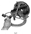
- FIG. 8A to 8C Perspective illustrations of the embodiment of Figs. 4 to 7 are shown in Figs. 8A to 8C .
- gripper 108 may have a pen-like shape.
- Product-like versions of a pen embodiment are shown in Figs. 9A to 9D .
- moveable members for one or more of the remaining fingers and also the thumb one or more moveable members, which are comparable in function and structure to moveable member 118, may be provided.
- moveable members for finger preferably are of the above described "G-type".
- moveable members for use with an active gripper may include a (curved) lever, piezo-electric actuator, electromagnetic actuator, magnetic actuator and hydraulic and/or pneumatic actuator.
- the associated contact surface may be provided on or may be formed by a moveable part the actuator.
- Active gravity compensation may be achieved by operating at least one of the device's actuators and/or at least one additional actuator (not shown) acting on the parallel kinematics claim 6 and/or pivotable connection of a wrist structure and/or gripper accordingly, i. e. moving the end-effector and/or the wrist structure of the gripper in directions opposite to gravity related movements.
Landscapes
- Engineering & Computer Science (AREA)
- Physics & Mathematics (AREA)
- General Physics & Mathematics (AREA)
- Robotics (AREA)
- Mechanical Engineering (AREA)
- Automation & Control Theory (AREA)
- General Engineering & Computer Science (AREA)
- Theoretical Computer Science (AREA)
- Human Computer Interaction (AREA)
- User Interface Of Digital Computer (AREA)
- Manipulator (AREA)
Claims (18)
- Haptische Vorrichtung umfassend- einen aktiven Greifer mit-- einer ersten Kontaktfläche (114), die ausgelegt ist zum Kontakt durch einen ersten Teil einer Hand eines Benutzers,-- einer zweiten Kontaktfläche (112), die ausgelegt ist zum Kontakt durch einen zweiten Teil der Hand des Benutzers, wobei der zweite Teil der Hand relativ zu dem ersten Teil der Hand bewegbar ist, und-- einem bewegbaren Glied (118), das zwischen der ersten Kontaktfläche (114) und der zweiten Kontaktfläche (112) angeordnet ist und eine Aktoreinrichtung zum aktiven Bewegen der ersten Kontaktfläche (114) und der zweiten Kontaktfläche (112) relativ zueinander umfasst;- eine Grundplatte (4);- einen Endeffektor (6), mit dem der aktive Greifer unmittelbar oder mittelbar verbunden ist; und- eine parallel-kinematische Struktur, die zwischen der Grundplatte (4) und dem Endeffektor (6) angeordnet ist;wobei die parallel-kinematische Struktur drei translatorische Freiheitsgrade bezüglich des Endeffektors (6) so bereitstellt, dass die Orientierung des Endeffektors (6) relativ zu der Grundplatte (4) gleich bleibt.
- Haptische Vorrichtung nach Anspruch 1, wobei die parallel-kinematische Struktur eine parallel-kinematische Delta-Struktur ist.
- Haptische Vorrichtung nach Anspruch 1 oder 2, wobei der aktive Greifer unmittelbar an dem Endeffektor (6) angebracht ist.
- Haptische Vorrichtung nach Anspruch 1 oder 2, ferner mit einer Gelenkstruktur (54, 100), die zwischen dem Endeffektor (6) und dem aktiven Greifer angeordnet ist, wobei die Gelenkstruktur (54, 100) wenigstens drei Freiheitsgrade für den aktiven Greifer bereitstellt, wobei von der Gelenkstruktur (54, 100) bereitgestellte rotatorische Freiheitsgrade vollständig von den translatorischen Freiheitsgraden der parallel-kinematischen Struktur entkoppelt sind.
- Haptische Vorrichtung nach Anspruch 4, wobei die Freiheitsgrade der Gelenkstruktur (54, 100) wenigstens teilweise aktiv sind.
- Haptische Vorrichtung nach Anspruch 4 oder 5, wobei die Gelenkstruktur (54, 100) rotatorische Freiheitsgrade bereitstellt.
- Haptische Vorrichtung nach einem der vorherigen Ansprüche, wobei rotatorische Achsen der Gelenkstruktur (54, 100) ein gemeinsames Rotationszentrum haben.
- Haptische Vorrichtung nach Anspruch 7, wobei beim Betrieb das gemeinsame Rotationszentrum innerhalb der Hand des Benutzers angeordnet ist, vorzugsweise zwischen dem Daumen des Benutzers und dem wenigstens einen anderen Finger, der in Kontakt mit dem aktiven Greifer steht.
- Haptische Vorrichtung nach einem der vorherigen Ansprüche, wobei die parallel-kinematische Struktur wenigstens einen den drei translatorischen Freiheitsgraden zugeordneten Aktor umfasst, wobei der wenigstens eine Aktor dazu dient, Kräfte und/oder Momente zur Übertragung zu dem Endeffektor (6) zu erzeugen, um für eine Kraftrückkopplung zu einem Benutzer zu sorgen.
- Haptische Vorrichtung nach einem der vorherigen Ansprüche, ferner umfassend- wenigstens eine weitere Kontaktfläche, die jeweils ausgelegt ist zum Kontakt durch einen weiteren Teil der Hand des Benutzers, wobei jeder weitere Teil der Hand relativ zu dem ersten Teil der Hand und/oder dem zweiten Teil der Hand und/oder einem anderen der weiteren Teile der Hand bewegbar ist; und- wenigstens ein weiteres bewegbares Glied, das jeweils einer der wenigstens einen weiteren Kontaktfläche zugeordnet ist und eine Aktoreinrichtung zum aktiven Bewegen der zugeordneten weiteren Kontaktfläche und wenigstens einer der übrigen Kontaktflächen relativ zueinander umfasst.
- Haptische Vorrichtung nach einem der vorherigen Ansprüche, wobei das wenigstens eine bewegbare Glied (118) in dem aktiven Greifer wenigstens eines eines G-förmigen Hebels, eines piezoelektrischen Aktors, eines elektromagnetischen Aktors, eines Magnetaktors und eines Hydraulik- oder Pneumatikaktors zum Erzeugen von Kraftrückkopplung aufweist.
- Haptische Vorrichtung nach einem der vorherigen Ansprüche, wobei der aktive Greifer einen rotatorischen Freiheitsgrad mittels eines rotatorischen Aktors zum Aufbringen eines Moments und/oder von Kraft auf den rotatorischen Freiheitsgrad bereitstellt, um für eine Kraftrückmeldung für einen Benutzer zu sorgen.
- Haptische Vorrichtung nach Anspruch 12, wobei der rotatorische Aktor mittels einer Kraft- und/oder Momentübertragungseinrichtung mit dem rotatorischen Freiheitsgrad verbunden ist.
- Haptische Vorrichtung nach Anspruch 13, wobei die Kraft- und/oder Momentübertragungseinrichtung ein Seil und eine Seilrolle umfasst.
- Haptische Vorrichtung nach einem der vorherigen Ansprüche, wobei der aktive Greifer wenigstens eines der folgenden Merkmale aufweist:- die erste Kontaktfläche (114) zum Kontakt durch wenigstens einen Finger der Hand des Benutzers, vorzugsweise ein Zeigefinger, ausgelegt ist,- die zweite Kontaktfläche (112) zum Kontakt durch einen Daumen der Hand des Benutzers ausgelegt ist.
- Haptische Vorrichtung nach einem der vorherigen Ansprüche, soweit von dem Anspruch 10 abhängig, wobei bei dem aktiven Greifer jede der wenigstens einen weiteren Kontaktfläche zum Kontakt durch eine Handfläche des Hand des Benutzers und/oder wenigstens einem Finger der Hand des Benutzers, vorzugsweise ein Mittelfinger, ein Ringfinger oder ein kleiner Finger, ausgelegt ist.
- Haptische Vorrichtung nach einem der vorherigen Ansprüche, wobei der aktive Greifer wenigstens eines der folgenden Merkmale aufweist:- die erste Kontaktfläche (114) an dem bewegbaren Glied (118) angeordnet ist,- die zweite Kontaktfläche (112) an einem Gehäuse (110) des aktiven Greifers ausgebildet ist, und- die wenigstens eine weitere Kontaktfläche an dem zugeordneten weiteren bewegbaren Glied angeordnet ist.
- Haptische Vorrichtung nach einem der vorherigen Ansprüche, wobei der aktive Greifer einen Freiheitsgrad mittels eines Druckknopfes oder Schalters bereitstellt.
Priority Applications (5)
| Application Number | Priority Date | Filing Date | Title |
|---|---|---|---|
| EP06013754A EP1876504B1 (de) | 2006-07-03 | 2006-07-03 | Aktiver Greifer für haptische Vorrichtungen |
| AT06013754T ATE525687T1 (de) | 2006-07-03 | 2006-07-03 | Aktiver greifer für haptische vorrichtungen |
| US12/306,825 US8667860B2 (en) | 2006-07-03 | 2007-06-26 | Active gripper for haptic devices |
| PCT/EP2007/005655 WO2008003416A1 (en) | 2006-07-03 | 2007-06-26 | Active gripper for haptic devices |
| US14/153,573 US20140192020A1 (en) | 2006-07-03 | 2014-01-13 | Active gripper for haptic devices |
Applications Claiming Priority (1)
| Application Number | Priority Date | Filing Date | Title |
|---|---|---|---|
| EP06013754A EP1876504B1 (de) | 2006-07-03 | 2006-07-03 | Aktiver Greifer für haptische Vorrichtungen |
Publications (2)
| Publication Number | Publication Date |
|---|---|
| EP1876504A1 EP1876504A1 (de) | 2008-01-09 |
| EP1876504B1 true EP1876504B1 (de) | 2011-09-21 |
Family
ID=37529407
Family Applications (1)
| Application Number | Title | Priority Date | Filing Date |
|---|---|---|---|
| EP06013754A Active EP1876504B1 (de) | 2006-07-03 | 2006-07-03 | Aktiver Greifer für haptische Vorrichtungen |
Country Status (4)
| Country | Link |
|---|---|
| US (2) | US8667860B2 (de) |
| EP (1) | EP1876504B1 (de) |
| AT (1) | ATE525687T1 (de) |
| WO (1) | WO2008003416A1 (de) |
Families Citing this family (32)
| Publication number | Priority date | Publication date | Assignee | Title |
|---|---|---|---|---|
| US10532466B2 (en) | 2008-08-22 | 2020-01-14 | Titan Medical Inc. | Robotic hand controller |
| US8332072B1 (en) | 2008-08-22 | 2012-12-11 | Titan Medical Inc. | Robotic hand controller |
| IT1394602B1 (it) * | 2009-05-19 | 2012-07-05 | Univ Bologna Alma Mater | Meccanismi rotazionali in catena chiusa con attuazione disaccoppiata ed omocinetica. |
| US8392023B2 (en) * | 2009-11-30 | 2013-03-05 | GM Global Technology Operations LLC | Photo-interrupter based force sensing handle and method of use |
| WO2012073789A1 (ja) * | 2010-11-30 | 2012-06-07 | オリンパス株式会社 | マスタ操作入力装置及びマスタスレーブマニピュレータ |
| CN102152314B (zh) * | 2010-12-13 | 2012-08-29 | 天津工业大学 | 触感装置中的夹持力反馈系统 |
| TR201807071T4 (tr) | 2011-06-21 | 2018-06-21 | Univ Sabanci | Diş i̇skelet. |
| US20140150593A1 (en) * | 2012-12-05 | 2014-06-05 | Alio Industries, Inc. | Precision tripod motion system |
| PL225105B1 (pl) | 2013-01-25 | 2017-02-28 | Przemysłowy Inst Automatyki I Pomiarów Piap | Urządzenie do sterowania o sześciu stopniach swobody |
| WO2015089729A1 (zh) * | 2013-12-17 | 2015-06-25 | 浙江理工大学 | 一种指尖力反馈装置 |
| EP4295801A3 (de) | 2014-05-05 | 2024-03-20 | Vicarious Surgical Inc. | Chirurgische virtual-reality-vorrichtung |
| CN105700783A (zh) * | 2014-11-26 | 2016-06-22 | 中国科学院沈阳自动化研究所 | 基于力反馈的安全远程力觉书写系统及其控制方法 |
| US9919424B1 (en) * | 2015-07-27 | 2018-03-20 | X Development Llc | Analog control switch for end-effector |
| CN112370008A (zh) | 2016-02-05 | 2021-02-19 | 得克萨斯系统大学董事会 | 手术设备 |
| CA3123794A1 (en) | 2016-02-05 | 2017-08-10 | Board Of Regents Of The University Of Texas System | Steerable intra-luminal medical device |
| US9889874B1 (en) * | 2016-08-15 | 2018-02-13 | Clause Technology | Three-axis motion joystick |
| US9823686B1 (en) * | 2016-08-15 | 2017-11-21 | Clause Technology | Three-axis motion joystick |
| CN106541390B (zh) * | 2016-10-31 | 2018-11-20 | 南京航空航天大学 | 一种混联六自由度力反馈设备及使用方法 |
| US10799308B2 (en) | 2017-02-09 | 2020-10-13 | Vicarious Surgical Inc. | Virtual reality surgical tools system |
| CN107066028A (zh) * | 2017-06-09 | 2017-08-18 | 河北工业大学 | 单控制手柄宏动六维控制器 |
| US11583342B2 (en) | 2017-09-14 | 2023-02-21 | Vicarious Surgical Inc. | Virtual reality surgical camera system |
| WO2019058336A1 (en) | 2017-09-23 | 2019-03-28 | Yazdian Seiedmuhammad | HANDLE FOR ROBOTIC SURGERY |
| AT520763B1 (de) * | 2017-12-21 | 2022-09-15 | Hans Kuenz Gmbh | Kransteuerung |
| CN109108949B (zh) * | 2018-10-23 | 2021-07-23 | 西安工程大学 | 具有3t、2t1r和1t2r三种运动模式的并联机构 |
| RU2718595C1 (ru) * | 2019-11-25 | 2020-04-08 | Ассистирующие Хирургические Технологии (Аст), Лтд | Контроллер оператора для управления роботохирургическим комплексом |
| RU2751779C1 (ru) * | 2020-07-07 | 2021-07-16 | Владимир Иванович Пожбелко | Копирующий манипулятор |
| US20230330865A1 (en) * | 2020-09-07 | 2023-10-19 | The Board Of Trustees Of The Leland Stanford Junior University | Drift-Based Adaptive Workspace Mapping Controller in Haptic Interaction |
| RU2757969C1 (ru) * | 2020-12-22 | 2021-10-25 | Акционерное общество "Казанский электротехнический завод" | Устройство управления манипуляторами роботохирургического комплекса |
| WO2023027095A1 (ja) | 2021-08-27 | 2023-03-02 | 国立大学法人東海国立大学機構 | マニピュレーションシステムおよびマニピュレーション方法 |
| KR102631432B1 (ko) * | 2021-12-29 | 2024-01-30 | 재단법인 구미전자정보기술원 | 수술로봇 조종을 위한 7 자유도를 갖는 소형 마스터 장치 |
| CN115256419B (zh) * | 2022-08-12 | 2023-08-04 | 中科院南昌高新技术产业协同创新研究院 | 一种临床手术模拟用机械臂及其模拟方法 |
| WO2024056183A1 (en) * | 2022-09-16 | 2024-03-21 | Force Dimension | Adjustable mechanical motion range limitation apparatus |
Family Cites Families (23)
| Publication number | Priority date | Publication date | Assignee | Title |
|---|---|---|---|---|
| GB955005A (en) | 1961-07-21 | 1964-04-08 | Molins Machine Co Ltd | Apparatus for gripping and lifting articles |
| US4216467A (en) * | 1977-12-22 | 1980-08-05 | Westinghouse Electric Corp. | Hand controller |
| US4555960A (en) | 1983-03-23 | 1985-12-03 | Cae Electronics, Ltd. | Six degree of freedom hand controller |
| CH672089A5 (de) * | 1985-12-16 | 1989-10-31 | Sogeva Sa | |
| US4795296A (en) | 1986-11-17 | 1989-01-03 | California Institute Of Technology | Hand-held robot end effector controller having movement and force control |
| US5004391A (en) | 1989-08-21 | 1991-04-02 | Rutgers University | Portable dextrous force feedback master for robot telemanipulation |
| WO1992005016A1 (en) | 1990-09-14 | 1992-04-02 | The Trustees Of The University Of Pennsylvania | Methods and apparatus for passively compensating for the effects of gravity upon articulated structures |
| US6024576A (en) * | 1996-09-06 | 2000-02-15 | Immersion Corporation | Hemispherical, high bandwidth mechanical interface for computer systems |
| EP2362283B1 (de) | 1997-09-19 | 2015-11-25 | Massachusetts Institute Of Technology | Robotergerät |
| GB9724453D0 (en) | 1997-11-20 | 1998-01-14 | Renishaw Plc | Measuring or positioning machine |
| US7337691B2 (en) * | 1999-08-05 | 2008-03-04 | Shambhu Nath Roy | Parallel kinematics mechanism with a concentric spherical joint |
| DE19957155C1 (de) | 1999-11-27 | 2001-06-21 | Stefan Stocker | Haptische Ein- und Ausgabevorrichtung und Verfahren für ein Manipulieren von virtuellen Objekten |
| US6377011B1 (en) * | 2000-01-26 | 2002-04-23 | Massachusetts Institute Of Technology | Force feedback user interface for minimally invasive surgical simulator and teleoperator and other similar apparatus |
| FR2809048B1 (fr) | 2000-05-18 | 2002-10-11 | Commissariat Energie Atomique | Bras de commande |
| AU2000260964A1 (en) | 2000-07-13 | 2002-01-30 | Rutgers, The State University Of New Jersey | Hand force feedback and sensing system |
| EP1199622B1 (de) | 2000-10-20 | 2007-12-12 | Deere & Company | Bedienungselement |
| US7877243B2 (en) | 2001-07-16 | 2011-01-25 | Immersion Corporation | Pivotable computer interface |
| DE10295032D2 (de) | 2001-10-29 | 2004-09-23 | Albert Schaeffer | Eingabegerät nach parallelkinematischem Prinzip und mit haptischer Rückkopplung |
| US7027031B2 (en) | 2002-02-07 | 2006-04-11 | Gifu University | Touch sense interface and method for controlling touch sense interface |
| KR100507554B1 (ko) * | 2003-05-21 | 2005-08-17 | 한국과학기술연구원 | 병렬형 햅틱 조이스틱 시스템 |
| FR2863534B1 (fr) | 2003-12-15 | 2007-01-05 | Commissariat Energie Atomique | Articulation de bras mecanique et bras pourvu de cette articulation |
| US8059089B2 (en) | 2004-05-25 | 2011-11-15 | Sony Computer Entertainment Inc. | Input device and method, and character input method |
| WO2006106419A2 (en) * | 2005-04-07 | 2006-10-12 | Perception Raisonnement Action En Medecine | Robotic guide assembly for use in computer-aided surgery |
-
2006
- 2006-07-03 AT AT06013754T patent/ATE525687T1/de not_active IP Right Cessation
- 2006-07-03 EP EP06013754A patent/EP1876504B1/de active Active
-
2007
- 2007-06-26 WO PCT/EP2007/005655 patent/WO2008003416A1/en not_active Ceased
- 2007-06-26 US US12/306,825 patent/US8667860B2/en active Active
-
2014
- 2014-01-13 US US14/153,573 patent/US20140192020A1/en not_active Abandoned
Also Published As
| Publication number | Publication date |
|---|---|
| WO2008003416A8 (en) | 2008-03-06 |
| EP1876504A1 (de) | 2008-01-09 |
| WO2008003416A1 (en) | 2008-01-10 |
| US20120090423A1 (en) | 2012-04-19 |
| US20140192020A1 (en) | 2014-07-10 |
| ATE525687T1 (de) | 2011-10-15 |
| US8667860B2 (en) | 2014-03-11 |
Similar Documents
| Publication | Publication Date | Title |
|---|---|---|
| US8667860B2 (en) | Active gripper for haptic devices | |
| US8188843B2 (en) | Haptic device gravity compensation | |
| US10071485B2 (en) | Hand controller device | |
| US10993774B2 (en) | Robotic hand controller | |
| US20060106369A1 (en) | Haptic interface for force reflection in manipulation tasks | |
| US5184319A (en) | Force feedback and textures simulating interface device | |
| Gupta et al. | Design of a haptic arm exoskeleton for training and rehabilitation | |
| JP3624374B2 (ja) | 力覚呈示装置 | |
| US6059506A (en) | Force feedback and texture simulating interface device | |
| KR101100983B1 (ko) | 피봇 가능한 컴퓨터 인터페이스 장치 및 피드백 제공 방법 | |
| Kawasaki et al. | Design and control of five-fingered haptic interface opposite to human hand | |
| Park et al. | A dual-cable hand exoskeleton system for virtual reality | |
| US10532466B2 (en) | Robotic hand controller | |
| WO2012127404A2 (en) | Ergonomic handle for haptic devices | |
| EP1629949B1 (de) | Haptische Schnittstellenvorrichtung | |
| Secco et al. | A wearable exoskeleton for hand kinesthetic feedback in virtual reality | |
| CN101739129B (zh) | 一种具有抓持力反馈的四自由度柔索驱动人机交互装置 | |
| Shanmugam et al. | A comprehensive review of haptic gloves: advances, challenges, and future directions | |
| Lelieveld et al. | Design and development of two concepts for a 4 DOF portable haptic interface with active and passive multi-point force feedback for the index finger | |
| Park et al. | Development of a dual-cable hand exoskeleton system for virtual reality | |
| Kawasaki et al. | Development of five-fingered haptic interface: HIRO-II | |
| Lelieveld et al. | Design and development of a 4 DOF portable haptic interface with multi-point passive force feedback for the index finger | |
| Ueda et al. | Development of a grounded haptic device and a 5-fingered robot hand for dexterous teleoperation | |
| Ye et al. | Haptic interface prototype for feedback control on robotic integration of smart sensors | |
| Secco¹ et al. | Feedback in Virtual Reality |
Legal Events
| Date | Code | Title | Description |
|---|---|---|---|
| PUAI | Public reference made under article 153(3) epc to a published international application that has entered the european phase |
Free format text: ORIGINAL CODE: 0009012 |
|
| AK | Designated contracting states |
Kind code of ref document: A1 Designated state(s): AT BE BG CH CY CZ DE DK EE ES FI FR GB GR HU IE IS IT LI LT LU LV MC NL PL PT RO SE SI SK TR |
|
| AX | Request for extension of the european patent |
Extension state: AL BA HR MK YU |
|
| 17P | Request for examination filed |
Effective date: 20080708 |
|
| 17Q | First examination report despatched |
Effective date: 20080815 |
|
| AKX | Designation fees paid |
Designated state(s): AT BE BG CH CY CZ DE DK EE ES FI FR GB GR HU IE IS IT LI LT LU LV MC NL PL PT RO SE SI SK TR |
|
| RIN1 | Information on inventor provided before grant (corrected) |
Inventor name: CONTI, FRANCOIS Inventor name: GRANGE, SEBASTIEN Inventor name: HELMER, PATRICK Inventor name: ROUILLER, PATRICE |
|
| GRAP | Despatch of communication of intention to grant a patent |
Free format text: ORIGINAL CODE: EPIDOSNIGR1 |
|
| GRAS | Grant fee paid |
Free format text: ORIGINAL CODE: EPIDOSNIGR3 |
|
| RAP1 | Party data changed (applicant data changed or rights of an application transferred) |
Owner name: FORCE DIMENSION TECHNOLOGIES SARL |
|
| GRAA | (expected) grant |
Free format text: ORIGINAL CODE: 0009210 |
|
| AK | Designated contracting states |
Kind code of ref document: B1 Designated state(s): AT BE BG CH CY CZ DE DK EE ES FI FR GB GR HU IE IS IT LI LT LU LV MC NL PL PT RO SE SI SK TR |
|
| REG | Reference to a national code |
Ref country code: GB Ref legal event code: FG4D |
|
| REG | Reference to a national code |
Ref country code: CH Ref legal event code: EP |
|
| REG | Reference to a national code |
Ref country code: IE Ref legal event code: FG4D |
|
| REG | Reference to a national code |
Ref country code: DE Ref legal event code: R096 Ref document number: 602006024494 Country of ref document: DE Effective date: 20111124 |
|
| REG | Reference to a national code |
Ref country code: NL Ref legal event code: VDEP Effective date: 20110921 |
|
| PG25 | Lapsed in a contracting state [announced via postgrant information from national office to epo] |
Ref country code: LT Free format text: LAPSE BECAUSE OF FAILURE TO SUBMIT A TRANSLATION OF THE DESCRIPTION OR TO PAY THE FEE WITHIN THE PRESCRIBED TIME-LIMIT Effective date: 20110921 Ref country code: SE Free format text: LAPSE BECAUSE OF FAILURE TO SUBMIT A TRANSLATION OF THE DESCRIPTION OR TO PAY THE FEE WITHIN THE PRESCRIBED TIME-LIMIT Effective date: 20110921 Ref country code: FI Free format text: LAPSE BECAUSE OF FAILURE TO SUBMIT A TRANSLATION OF THE DESCRIPTION OR TO PAY THE FEE WITHIN THE PRESCRIBED TIME-LIMIT Effective date: 20110921 |
|
| LTIE | Lt: invalidation of european patent or patent extension |
Effective date: 20110921 |
|
| PG25 | Lapsed in a contracting state [announced via postgrant information from national office to epo] |
Ref country code: CY Free format text: LAPSE BECAUSE OF FAILURE TO SUBMIT A TRANSLATION OF THE DESCRIPTION OR TO PAY THE FEE WITHIN THE PRESCRIBED TIME-LIMIT Effective date: 20110921 Ref country code: GR Free format text: LAPSE BECAUSE OF FAILURE TO SUBMIT A TRANSLATION OF THE DESCRIPTION OR TO PAY THE FEE WITHIN THE PRESCRIBED TIME-LIMIT Effective date: 20111222 Ref country code: SI Free format text: LAPSE BECAUSE OF FAILURE TO SUBMIT A TRANSLATION OF THE DESCRIPTION OR TO PAY THE FEE WITHIN THE PRESCRIBED TIME-LIMIT Effective date: 20110921 Ref country code: AT Free format text: LAPSE BECAUSE OF FAILURE TO SUBMIT A TRANSLATION OF THE DESCRIPTION OR TO PAY THE FEE WITHIN THE PRESCRIBED TIME-LIMIT Effective date: 20110921 Ref country code: LV Free format text: LAPSE BECAUSE OF FAILURE TO SUBMIT A TRANSLATION OF THE DESCRIPTION OR TO PAY THE FEE WITHIN THE PRESCRIBED TIME-LIMIT Effective date: 20110921 |
|
| REG | Reference to a national code |
Ref country code: AT Ref legal event code: MK05 Ref document number: 525687 Country of ref document: AT Kind code of ref document: T Effective date: 20110921 |
|
| PG25 | Lapsed in a contracting state [announced via postgrant information from national office to epo] |
Ref country code: BE Free format text: LAPSE BECAUSE OF FAILURE TO SUBMIT A TRANSLATION OF THE DESCRIPTION OR TO PAY THE FEE WITHIN THE PRESCRIBED TIME-LIMIT Effective date: 20110921 |
|
| PG25 | Lapsed in a contracting state [announced via postgrant information from national office to epo] |
Ref country code: SK Free format text: LAPSE BECAUSE OF FAILURE TO SUBMIT A TRANSLATION OF THE DESCRIPTION OR TO PAY THE FEE WITHIN THE PRESCRIBED TIME-LIMIT Effective date: 20110921 Ref country code: IS Free format text: LAPSE BECAUSE OF FAILURE TO SUBMIT A TRANSLATION OF THE DESCRIPTION OR TO PAY THE FEE WITHIN THE PRESCRIBED TIME-LIMIT Effective date: 20120121 Ref country code: CZ Free format text: LAPSE BECAUSE OF FAILURE TO SUBMIT A TRANSLATION OF THE DESCRIPTION OR TO PAY THE FEE WITHIN THE PRESCRIBED TIME-LIMIT Effective date: 20110921 |
|
| PG25 | Lapsed in a contracting state [announced via postgrant information from national office to epo] |
Ref country code: PL Free format text: LAPSE BECAUSE OF FAILURE TO SUBMIT A TRANSLATION OF THE DESCRIPTION OR TO PAY THE FEE WITHIN THE PRESCRIBED TIME-LIMIT Effective date: 20110921 Ref country code: RO Free format text: LAPSE BECAUSE OF FAILURE TO SUBMIT A TRANSLATION OF THE DESCRIPTION OR TO PAY THE FEE WITHIN THE PRESCRIBED TIME-LIMIT Effective date: 20110921 Ref country code: NL Free format text: LAPSE BECAUSE OF FAILURE TO SUBMIT A TRANSLATION OF THE DESCRIPTION OR TO PAY THE FEE WITHIN THE PRESCRIBED TIME-LIMIT Effective date: 20110921 Ref country code: EE Free format text: LAPSE BECAUSE OF FAILURE TO SUBMIT A TRANSLATION OF THE DESCRIPTION OR TO PAY THE FEE WITHIN THE PRESCRIBED TIME-LIMIT Effective date: 20110921 Ref country code: PT Free format text: LAPSE BECAUSE OF FAILURE TO SUBMIT A TRANSLATION OF THE DESCRIPTION OR TO PAY THE FEE WITHIN THE PRESCRIBED TIME-LIMIT Effective date: 20120123 Ref country code: IT Free format text: LAPSE BECAUSE OF FAILURE TO SUBMIT A TRANSLATION OF THE DESCRIPTION OR TO PAY THE FEE WITHIN THE PRESCRIBED TIME-LIMIT Effective date: 20110921 |
|
| PLBE | No opposition filed within time limit |
Free format text: ORIGINAL CODE: 0009261 |
|
| STAA | Information on the status of an ep patent application or granted ep patent |
Free format text: STATUS: NO OPPOSITION FILED WITHIN TIME LIMIT |
|
| PG25 | Lapsed in a contracting state [announced via postgrant information from national office to epo] |
Ref country code: DK Free format text: LAPSE BECAUSE OF FAILURE TO SUBMIT A TRANSLATION OF THE DESCRIPTION OR TO PAY THE FEE WITHIN THE PRESCRIBED TIME-LIMIT Effective date: 20110921 |
|
| 26N | No opposition filed |
Effective date: 20120622 |
|
| REG | Reference to a national code |
Ref country code: DE Ref legal event code: R097 Ref document number: 602006024494 Country of ref document: DE Effective date: 20120622 |
|
| PG25 | Lapsed in a contracting state [announced via postgrant information from national office to epo] |
Ref country code: MC Free format text: LAPSE BECAUSE OF NON-PAYMENT OF DUE FEES Effective date: 20120731 |
|
| PG25 | Lapsed in a contracting state [announced via postgrant information from national office to epo] |
Ref country code: ES Free format text: LAPSE BECAUSE OF FAILURE TO SUBMIT A TRANSLATION OF THE DESCRIPTION OR TO PAY THE FEE WITHIN THE PRESCRIBED TIME-LIMIT Effective date: 20120101 |
|
| REG | Reference to a national code |
Ref country code: IE Ref legal event code: MM4A |
|
| PG25 | Lapsed in a contracting state [announced via postgrant information from national office to epo] |
Ref country code: BG Free format text: LAPSE BECAUSE OF FAILURE TO SUBMIT A TRANSLATION OF THE DESCRIPTION OR TO PAY THE FEE WITHIN THE PRESCRIBED TIME-LIMIT Effective date: 20111221 |
|
| PG25 | Lapsed in a contracting state [announced via postgrant information from national office to epo] |
Ref country code: IE Free format text: LAPSE BECAUSE OF NON-PAYMENT OF DUE FEES Effective date: 20120703 |
|
| PG25 | Lapsed in a contracting state [announced via postgrant information from national office to epo] |
Ref country code: TR Free format text: LAPSE BECAUSE OF FAILURE TO SUBMIT A TRANSLATION OF THE DESCRIPTION OR TO PAY THE FEE WITHIN THE PRESCRIBED TIME-LIMIT Effective date: 20110921 |
|
| PG25 | Lapsed in a contracting state [announced via postgrant information from national office to epo] |
Ref country code: LU Free format text: LAPSE BECAUSE OF NON-PAYMENT OF DUE FEES Effective date: 20120703 |
|
| PG25 | Lapsed in a contracting state [announced via postgrant information from national office to epo] |
Ref country code: HU Free format text: LAPSE BECAUSE OF FAILURE TO SUBMIT A TRANSLATION OF THE DESCRIPTION OR TO PAY THE FEE WITHIN THE PRESCRIBED TIME-LIMIT Effective date: 20060703 |
|
| REG | Reference to a national code |
Ref country code: FR Ref legal event code: PLFP Year of fee payment: 11 |
|
| REG | Reference to a national code |
Ref country code: FR Ref legal event code: PLFP Year of fee payment: 12 |
|
| REG | Reference to a national code |
Ref country code: FR Ref legal event code: PLFP Year of fee payment: 13 |
|
| PGFP | Annual fee paid to national office [announced via postgrant information from national office to epo] |
Ref country code: DE Payment date: 20250722 Year of fee payment: 20 |
|
| PGFP | Annual fee paid to national office [announced via postgrant information from national office to epo] |
Ref country code: GB Payment date: 20250722 Year of fee payment: 20 |
|
| PGFP | Annual fee paid to national office [announced via postgrant information from national office to epo] |
Ref country code: FR Payment date: 20250723 Year of fee payment: 20 |
|
| PGFP | Annual fee paid to national office [announced via postgrant information from national office to epo] |
Ref country code: CH Payment date: 20250801 Year of fee payment: 20 |