EP1876568A2 - Système, méthode et moyen de détection d'un objet en mouvement par l'utilisation d'une lumière structurée. Robot mobile incluant ce système - Google Patents
Système, méthode et moyen de détection d'un objet en mouvement par l'utilisation d'une lumière structurée. Robot mobile incluant ce système Download PDFInfo
- Publication number
- EP1876568A2 EP1876568A2 EP07111629A EP07111629A EP1876568A2 EP 1876568 A2 EP1876568 A2 EP 1876568A2 EP 07111629 A EP07111629 A EP 07111629A EP 07111629 A EP07111629 A EP 07111629A EP 1876568 A2 EP1876568 A2 EP 1876568A2
- Authority
- EP
- European Patent Office
- Prior art keywords
- image
- distance data
- calculated
- data
- light source
- Prior art date
- Legal status (The legal status is an assumption and is not a legal conclusion. Google has not performed a legal analysis and makes no representation as to the accuracy of the status listed.)
- Granted
Links
Images


Classifications
-
- G—PHYSICS
- G06—COMPUTING OR CALCULATING; COUNTING
- G06T—IMAGE DATA PROCESSING OR GENERATION, IN GENERAL
- G06T7/00—Image analysis
-
- G—PHYSICS
- G06—COMPUTING OR CALCULATING; COUNTING
- G06T—IMAGE DATA PROCESSING OR GENERATION, IN GENERAL
- G06T7/00—Image analysis
- G06T7/20—Analysis of motion
- G06T7/254—Analysis of motion involving subtraction of images
-
- G—PHYSICS
- G06—COMPUTING OR CALCULATING; COUNTING
- G06T—IMAGE DATA PROCESSING OR GENERATION, IN GENERAL
- G06T7/00—Image analysis
- G06T7/20—Analysis of motion
-
- G—PHYSICS
- G06—COMPUTING OR CALCULATING; COUNTING
- G06T—IMAGE DATA PROCESSING OR GENERATION, IN GENERAL
- G06T7/00—Image analysis
- G06T7/40—Analysis of texture
-
- G—PHYSICS
- G06—COMPUTING OR CALCULATING; COUNTING
- G06V—IMAGE OR VIDEO RECOGNITION OR UNDERSTANDING
- G06V10/00—Arrangements for image or video recognition or understanding
- G06V10/10—Image acquisition
- G06V10/12—Details of acquisition arrangements; Constructional details thereof
- G06V10/14—Optical characteristics of the device performing the acquisition or on the illumination arrangements
- G06V10/145—Illumination specially adapted for pattern recognition, e.g. using gratings
-
- G—PHYSICS
- G06—COMPUTING OR CALCULATING; COUNTING
- G06V—IMAGE OR VIDEO RECOGNITION OR UNDERSTANDING
- G06V10/00—Arrangements for image or video recognition or understanding
- G06V10/20—Image preprocessing
- G06V10/24—Aligning, centring, orientation detection or correction of the image
-
- G—PHYSICS
- G06—COMPUTING OR CALCULATING; COUNTING
- G06T—IMAGE DATA PROCESSING OR GENERATION, IN GENERAL
- G06T2207/00—Indexing scheme for image analysis or image enhancement
- G06T2207/10—Image acquisition modality
- G06T2207/10028—Range image; Depth image; 3D point clouds
Definitions
- Embodiments relate to detecting a moving object using a structured light, and more particularly, to a system, a method, and medium that can detect the moving object even while moving by predicting an image after the movement from an existing image and comparing the predicted image with the present image, detect a broad range, and detect the moving object even when lighting is absent.
- a mobile robot that can move by itself can be used in an extended work area such as an arbitrary work place or an outdoor place. Accordingly, the mobile robot is superior to the stationary robot because the mobile robot can perform more various roles and tasks.
- detecting apparatuses of the related art are configured so as to survey only a certain range by using one stationary camera. That is, the detecting apparatus according to the related art expects a photographic angle in advance and photographs within only the expected angle. Therefore, the surveillance apparatus according to the related art could observe only a limited range.
- the installed camera device is re-installed. Therefore, in the case of detecting a number of ranges in one space, a number of cameras should be installed.
- a method for actively detecting a moving object stores an image signal in a stationary image apparatus, creates a differential image by comparing the stored image with the present image, and extracts the moving object.
- the image apparatus also obtains the image signal in only the stationary state. Therefore, a method, in which an image apparatus can detect a moving object while the image apparatus is moving, is not provided.
- Embodiments provide an apparatus, method, and medium to solve the above-described problems.
- a system and a method for detecting a moving object and a mobile robot including the system that can detect the moving object even while the mobile robot is moving by predicting an image after the movement from an existing image and comparing the predicted image with the present image.
- a system for detecting a moving object using a structured light including an image obtaining unit to obtain a first image at a predetermined position and a second image at a position after a movement of the system by using a light source; an image predicting unit to predict the second image at the position after the movement of the system by using the first image and information pertaining to the movement of the system; and a comparing / analyzing unit to compare and analyze the second image obtained by the image obtaining unit and the second image predicted by the image predicting unit to detect the moving object.
- a method for detecting a moving object using a structured light including obtaining a first image at a predetermined position by using a light source; predicting a second image at a position after the movement of the system by using the first image and information pertaining to the movement of the system; obtaining the second image at the position after the movement of the system; and detecting the moving object by comparing the predicted second image with the obtained second image.
- a mobile robot for a moving object using a structured light including a system to detect a moving object; and a driving system to drive the mobile robot which calculates position and recognizes the moving object.
- the system for detecting the moving object includes an image obtaining unit to obtain a first image at a predetermined position and a second image at a position after a movement of the system by a light source; an image predicting unit to predict the second image at the position after the movement of the system by using the first image and information pertaining to the movement of the system; and a comparing / analyzing unit to compare and analyze the second image obtained by the image obtaining unit and the second image predicted by the image predicting unit to detect the moving object.
- At least one computer readable medium storing computer readable instructions to implement methods of embodiments.
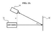
- FIG. 1A is a side view showing an apparatus and a method of obtaining a structured light image according to an exemplary embodiment
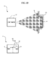
- FIG. 1B is a view showing a shape for producing a light source 10 on an obstacle 30 and a camera image 40 obtained by a camera sensor 20 in order to obtain a structured light image according to an exemplary embodiment
- the obstacle 30 may be capable of movement, for example a moving object.
- An exemplary embodiment may illuminate light on the obstacle 30 by using an active light source 10 such as a laser and obtain image information reflected from the obstacle 30 by using a sensor 20 such as a camera.
- the camera sensor 20 is disposed in relationship to the light source 10 to maintain a constant distance d from the light source 10 and to obtain the image information.
- the light source 10 may use a near-infrared laser beam. By using the near-infrared laser beam, it may obtain image information even if lighting is absent.
- the laser beam is illuminated in a plane on the obstacle 30 from the light source 10 while having a constant visual angle a .
- the B of FIG. 1B indicates a camera image 40 of a line profile shape which the camera sensor 20 obtains.
- light reflected from point "a" and “b" of the obstacle 30 indicate “a” and “b” of the camera image 40, respectively, and a Y-axis direction indicates the distance between the camera sensor 20 and the obstacle 30.
- a distance data between the light source 10 and the obstacle 30 may be calculated by a triangular method on the basis of the distance between the camera sensor 20 and the obstacle 30 obtained from the coordinates of the camera image 40, an angle ⁇ of the camera sensor 20 that is inclined toward the obstacle 30, and the distance d between the camera sensor 20 and the light source 10. Since the triangular method is known to those skilled in the art, the detailed description thereof is omitted.
- a process for detecting a moving object by calculating the distance data between the light source 10 and the obstacle 30 from the camera image 40 obtained by the camera sensor 20 will be described.
- Fig. 2 is a block diagram of a system of detecting a moving object using a structured light according to an exemplary embodiment.
- the system 100 for detecting a moving object includes an image obtaining (capturing) unit 110 that obtains (captures) the image information of the obstacle 30, an image predicting unit 120 that predicts the image information obtained by the image obtaining unit 110 and an image at a moved position from the moving information of the system 100, and a comparing / analyzing unit 130 that compares and analyzes the obtained image and the predicted image.
- the image predicting unit 120 may include a data converting unit 122 that converts the distance calculated from the image information into the distance data predicted from the moving information of the system 100 and a data extracting unit 124 that extracts the data deviated from the visual angle ⁇ of the light source 10 from the predicted distance data after the system 100 is moved.
- An exemplary embodiment may obtain a first image by using the light source 10 in the image obtaining unit 110 and calculate the distance data between the light source 10 and the obstacle 30 by the triangular method as described above.
- the distance data of a second image that is an image at the moved position may be predicted by calculation through the data converting unit 122 and the data extracting unit 124 in the image predicting unit 120.
- the second image may be obtained (captured) by using the light source 10 in the image obtaining unit 110. Accordingly, it may detect the moving object by comparing the distance data calculated from the second image and the distance data of the predicted second image in the comparing / analyzing unit 130.
- FIG. 3 is a view illustrating a process of detecting a moving object after obtaining a first image and a second image after a movement.
- a first image is obtained in the image obtaining unit 110 by receiving a structured light that is horizontally illuminated from a system 100a and reflected through the camera sensor 20.
- the obtained camera image 40 is converted into the distance data by the above-described triangular method.
- the distance data is the data in which "a region" of a dotted line and "b region" a bolded straight line in FIG. 3 are indicated by a coordinate system.
- the light source 10 at which the system 100a is located is defined as an origin
- an x-axis is defined as a data axis
- a y-axis is defined as a distance axis indicating a distance from the light source 10 to the obstacle 30.
- the x-axis includes a negative x-axis that is a left side of the origin and a positive x-axis that is a right side of the origin.
- A it may be expressed as follows.
- subscripts 1, 2, ..., n indicate n distance data obtained from the structured light
- x n and y n indicate coordinate values of each distance data.
- the system 100a After the image obtaining unit 110 obtains the first image information, the system 100a continuously moves.
- a process of predicting the distance data of the second image which is the image at the position after the system 100a is moved during a predetermined time, in the image predicting unit 120 will be described.
- the system 100b each moves by T x and T y in an x direction and a y direction and rotates by ⁇ angle.
- a moving distance and a rotational angle may be calculated from an encoder of the system 100b, a gyro, a dead reckoning system or the like. Therefore, assuming a moving vector T and a rotational matrix R as follow, a data converting unit 122 may convert the distance data A into a predicted distance data A' after the system is moved from following equation 1.
- T ⁇ T x T y ⁇
- R cos ⁇ sin ⁇ - sin ⁇ cos ⁇
- a detecting area of the first image information and a detecting area of the second image information are varied by the movement and the rotation of the system 100.
- the reason is that the visual angle a of the light source 10 is constant, while the position and the angle of the system 100 are changed.
- the data extracting unit 124 extracts the data of the common region (b region) of the predicted distance data A' (a region and b region) converted in the data converting unit 122 and the distance data (b region and c region) within the visual angle ⁇ of the second image at the position after the system is moved.
- the data extracting unit 124 extracts the data that deviates from the visual angle a of the system 100b after the movement of the system 100a out of the predicted distance data A' of the position after the movement, which are converted in the data converting unit 122.
- the data of A is extracted from the predicted data.
- the distance data of the second image which is predicted in the image predicting unit 120, are the data of the b region illustrated by the x and y coordinate system.
- the second image predicted in the image predicting unit 120 will be compared with the second image obtained in the image obtaining unit 110.
- the second image is obtained in the image obtaining unit 110 of the system 100b by receiving a structured light that is horizontally illuminated from a system 100b and reflected through the camera sensor 20.
- the obtained camera image 40 is converted into the distance data by the above-described triangular method.
- the distance data of the second region predicted in the image predicting unit 120 is the distance data of the b region and the distance data of the obtained second image is the data of the b region and the c region.
- Each data is the data on the basis of the x'-y' coordinate system. Accordingly, the comparing region should be limited to the b region out of the distance data calculated from the second image that is obtained in the image obtaining unit 110.
- a minimum value x'min and a maximum value x'max of x' may be calculated from the predicted second image of the distance data.
- the minimum value is the boundary of the "a" region and the "b” region
- the maximum value is the boundary of the "b” region and the "c” region. Therefore, it may detect the moving object by comparing the distance data (b region) between the x' min and the x' max out of the distance data obtained from the second image with the finally predicted distance data (b region) through the data converting unit 122 and the data extracting unit 124 of the image predicting unit 120.
- both the distance data of the predicted second image and the distance data of the second image will have an approximately equal value. Furthermore, if the moving object exists, a part of both values of the distance data of the predicted second image and the distance data of the second image may be largely changed. At this time, the moving object may be an intruder in a constant region and/or may be a moving animal.
- the distance data of the predicted second image and the distance data of the second image are compared by the related art split-merge method that extracts corner points on the basis of a distance threshold in proportion to the distance data corresponding to pixel information of the structured light image, generates the straight line that joints together the corner points, and compares each segment of lines. It may detect the moving object by the split-merge method. This will be described with reference to drawings below.
- FIG. 4A is a view showing an example for detecting a moving object (e.g., intruder) from a distance data of a predicted second image and a distance data of an obtained second image
- FIG. 4B is a view showing a straight line joined together by extracting corner points so as to compare a distance data of an obtained second image with a distance data of a predicted second image.
- a moving object e.g., intruder
- FIG. 4A shows the distance data when the intruder appears in the second image after the system advances in 300 mm, while the intruder does not exist in the first image.
- all of the distance data (the distance data of the obtained first image) before the movement do not change into the predicted distance data (the distance data of the predicted second image), but the only data within the range of the visual angle a of the system 100 after the movement is extracted.
- the predicted data of the second image does not appear in -600 ⁇ -500 and 500 ⁇ 600 in the x-axis range as compared with the distance data of the first image.
- the data after the movement is in the shape of two legs that break between the two legs as compared with the predicted data.
- the comparing / analyzing unit 130 determines that it detects the moving object (intruder). Accordingly, the system 100 may sound the alarm to inform the user, or take follow-up measures such as an actuation of the security apparatus. Referring to FIG. 5B, it may compare both distance data by extracting a corner point from the respective data, generating the straight lines, and comparing the generated straight lines with each other by the above-mentioned method in the related art.
- the system 100 detects the moving object, it takes follow-up measures described above. However, when determined that there is no large difference by comparing the second distance data predicted in the comparing / analyzing unit 130 with the second distance data obtained, the system obtains the first image as well as the above method, and repeats the above process. Preferably, it may repeat the above process by treating the obtained second image as the first image.
- FIG. 5A is a view showing a first structured light image when an intruder appears and a second structured light image after a system 100 advances in 300 mm when the intruder moves.
- FIG. 5B is a view showing one for detecting a moving object by using the structured light image of FIG. 5A according to an exemplary embodiment.
- the first structured image of FIG. 5A is one that photographs a corner of a wall.
- a two-piece image which breaks in the middle of the structured light image and shortly appears below, shows the legs of the intruder.
- the second structured light image looks like an enlarged picture of the first image and shows only one leg.
- the predicted data distance data of the predicted second image
- the predicted data is to advance the distance data (data before the movement) obtained from the first image by a constant distance. All the data of the first image does not advance, but data of both sides are extracted due to the visual angle ⁇ after the movement.
- the comparing / analyzing unit 130 of the system 100 may determine that it detects the moving object.
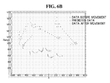
- FIG. 6A is a view showing a first structured light image when an intruder appears and a second structured light image after a system 100 rotates at 20 degrees in a clockwise direction.
- FIG. 6B is a view showing an example for detecting a moving object by using the structured light image of FIG. 6A according to an exemplary embodiment.
- the predicted data is the distance data (distance data before the movement) obtained from the first image by 20 degrees in a counterclockwise direction. It may know that all the data of the first image does not shift, but data of the left wall are extracted due to the visual angle ⁇ after the movement.
- a part showing the stationary wall is similar, but the position difference of the data showing by the legs of the intruder.
- the comparing / analyzing unit 130 of the system 100 may determine that it detects the moving object.
- FIG. 7A is a flowchart showing a method of detecting a moving object using a structured light according to an exemplary embodiment
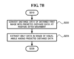
- FIG. 7B is a detailed flowchart of step (S220) predicting the second image of FIG. 7A according to an exemplary embodiment.
- a method for detecting the moving object using the structured light includes obtaining (S210) a first image of the obstacle 30 in an image obtaining unit 110, predicting (S220) a second image from the first image a moving information (moving vector and rotational angle) in an image predicting unit 120, obtaining (S230) the second image in the image obtaining unit 110, and comparing (S240) the predicted second image with the obtained second image in a comparing / analyzing unit 130.
- the first image is obtained again, and the above steps are repeated.
- the obtained second image is similar to the following first image. If determining (S250) that the predicted image and the obtained image are different from each other, the system may sound the alarm to inform the user, or take follow-up measures such as an actuation of the security system (S260).
- Step (S220) predicting the second image may include converting (S222) the distance data calculated from the first image information into the predicted distance data after the movement from the moving information (moving vector and rotational angle) in a data converting unit 122 and extracting (S224) only the data in the range of the visual angle ⁇ after the movement among the predicted distance data after the movement in a data extracting unit 124.
- the mobile robot may be used as a security robot for surveying the intruder while moving.
- exemplary embodiments can also be implemented by executing computer readable code/instructions in/on a medium/media, e.g., a computer readable medium/media.
- the medium/media can correspond to any medium/media permitting the storing and/or transmission of the computer readable code/instructions.
- the medium/media may also include, alone or in combination with the computer readable code/instructions, data files, data structures, and the like. Examples of code/instructions include both machine code, such as produced by a compiler, and files containing higher level code that may be executed by a computing device and the like using an interpreter.
- code/instructions may include functional programs and code segments.
- the computer readable code/instructions can be recorded/transferred in/on a medium/media in a variety of ways, with examples of the medium/media including magnetic storage media (e.g., floppy disks, hard disks, magnetic tapes, etc.), optical media (e.g., CD-ROMs, DVDs, etc.), magneto-optical media (e.g., floptical disks), hardware storage devices (e.g., read only memory media, random access memory media, flash memories, etc.) and storage/transmission media such as carrier waves transmitting signals, which may include computer readable code/instructions, data files, data structures, etc. Examples of storage/transmission media may include wired and/or wireless transmission media.
- magnetic storage media e.g., floppy disks, hard disks, magnetic tapes, etc.
- optical media e.g., CD-ROMs, DVDs, etc.
- magneto-optical media e.g., floptical disks
- hardware storage devices
- the medium/media may also be a distributed network, so that the computer readable code/instructions are stored/transferred and executed in a distributed fashion.
- the computer readable code/instructions may be executed by one or more processors.
- the computer readable code/instructions may also be executed and/or embodied in at least one application specific integrated circuit (ASIC) or Field Programmable Gate Array (FPGA) .
- ASIC application specific integrated circuit
- FPGA Field Programmable Gate Array
- one or more software modules or one or more hardware modules may be configured in order to perform the operations of the above-described exemplary embodiments.
- module denotes, but are not limited to, a software component, a hardware component, a plurality of software components, a plurality of hardware components, a combination of a software component and a hardware component, a combination of a plurality of software components and a hardware component, a combination of a software component and a plurality of hardware components, or a combination of a plurality of software components and a plurality of hardware components, which performs certain tasks.
- a module may advantageously be configured to reside on the addressable storage medium/media and configured to execute on one or more processors.
- a module may include, by way of example, components, such as software components, application specific software components, object-oriented software components, class components and task components, processes, functions, operations, execution threads, attributes, procedures, subroutines, segments of program code, drivers, firmware, microcode, circuitry, data, databases, data structures, tables, arrays, and variables.
- components such as software components, application specific software components, object-oriented software components, class components and task components, processes, functions, operations, execution threads, attributes, procedures, subroutines, segments of program code, drivers, firmware, microcode, circuitry, data, databases, data structures, tables, arrays, and variables.
- the functionality provided for in the components or modules may be combined into fewer components or modules or may be further separated into additional components or modules.
- the components or modules can operate at least one processor (e.g. central processing unit (CPU)) provided in a device.
- processor e.g. central processing unit (CPU)
- examples of a hardware components include an application specific integrated circuit (ASIC) and
- the computer readable code/instructions and computer readable medium/media may be those specially designed and constructed for the purposes of embodiments, or they may be of the kind well-known and available to those skilled in the art of computer hardware and/or computer software.
Landscapes
- Engineering & Computer Science (AREA)
- Physics & Mathematics (AREA)
- General Physics & Mathematics (AREA)
- Theoretical Computer Science (AREA)
- Multimedia (AREA)
- Computer Vision & Pattern Recognition (AREA)
- Artificial Intelligence (AREA)
- Image Analysis (AREA)
Applications Claiming Priority (1)
| Application Number | Priority Date | Filing Date | Title |
|---|---|---|---|
| KR1020060063156A KR100801087B1 (ko) | 2006-07-05 | 2006-07-05 | 스트럭처드 라이트를 이용한 이동체 감지 시스템 및 방법,상기 시스템을 포함하는 이동 로봇 |
Publications (3)
| Publication Number | Publication Date |
|---|---|
| EP1876568A2 true EP1876568A2 (fr) | 2008-01-09 |
| EP1876568A3 EP1876568A3 (fr) | 2010-09-01 |
| EP1876568B1 EP1876568B1 (fr) | 2014-06-11 |
Family
ID=38474383
Family Applications (1)
| Application Number | Title | Priority Date | Filing Date |
|---|---|---|---|
| EP07111629.7A Active EP1876568B1 (fr) | 2006-07-05 | 2007-07-03 | Système, méthode et moyen de détection d'un objet en mouvement par l'utilisation d'une lumière structurée. Robot mobile incluant ce système |
Country Status (4)
| Country | Link |
|---|---|
| US (1) | US7983449B2 (fr) |
| EP (1) | EP1876568B1 (fr) |
| KR (1) | KR100801087B1 (fr) |
| CN (1) | CN101101204B (fr) |
Cited By (4)
| Publication number | Priority date | Publication date | Assignee | Title |
|---|---|---|---|---|
| WO2011088254A3 (fr) * | 2010-01-14 | 2011-11-24 | Alces Technology, Inc. | Système à lumière structurée |
| CN103185567A (zh) * | 2011-12-27 | 2013-07-03 | 联想(北京)有限公司 | 一种电子设备及测量距离的方法 |
| US8723923B2 (en) | 2010-01-14 | 2014-05-13 | Alces Technology | Structured light system |
| US9389069B2 (en) | 2014-03-26 | 2016-07-12 | Alces Technology, Inc. | Compact 3D depth capture systems |
Families Citing this family (27)
| Publication number | Priority date | Publication date | Assignee | Title |
|---|---|---|---|---|
| EP1571584A1 (fr) * | 2004-03-03 | 2005-09-07 | Honda Research Institute Europe GmbH | Intégration visuelle d'information d'objet dans un environnement de réseaux d'ordinateurs omniprésent |
| KR100587572B1 (ko) * | 2004-10-15 | 2006-06-08 | 삼성전자주식회사 | 카메라 픽셀 정보를 이용하여 공간상의 코너 포인트를추출하는 시스템 및 방법, 상기 시스템을 포함하는 이동로봇 |
| EP2165603A1 (fr) * | 2008-09-23 | 2010-03-24 | Koninklijke Philips Electronics N.V. | Procédé et système d'éclairage adapté pour les animaux |
| TWI420421B (zh) * | 2009-09-16 | 2013-12-21 | Univ Nat Kaohsiung Applied Sci | Automatic patrol tracing to capture the system |
| KR101634355B1 (ko) * | 2009-09-18 | 2016-06-28 | 삼성전자주식회사 | 동작 검출 장치 및 방법 |
| CN101698263B (zh) * | 2009-10-23 | 2011-12-21 | 天津大学 | 带有结构光检测的三割炬h型钢双端自动切割机 |
| CN102466479B (zh) * | 2010-11-16 | 2013-08-21 | 深圳泰山在线科技有限公司 | 一种运动物体的抗干扰距离测量系统及方法 |
| CN102866433B (zh) * | 2011-07-05 | 2015-11-25 | 科沃斯机器人有限公司 | 探测自移动机器人周边障碍物的探测装置及自移动机器人 |
| TW201322179A (zh) * | 2011-11-28 | 2013-06-01 | Hon Hai Prec Ind Co Ltd | 街景建立系統及街景建立方法 |
| CN103136784B (zh) * | 2011-11-29 | 2016-08-03 | 鸿富锦精密工业(深圳)有限公司 | 街景建立系统及街景建立方法 |
| EP2631730B1 (fr) * | 2012-02-24 | 2014-09-24 | Samsung Electronics Co., Ltd | Capteur et robot nettoyeur muni dudit capteur |
| CN105929819B (zh) * | 2012-02-27 | 2021-10-22 | 联想(北京)有限公司 | 一种控制电子设备的方法及电子设备 |
| CN102773862B (zh) * | 2012-07-31 | 2015-01-07 | 山东大学 | 用于室内移动机器人的快速精确定位系统及其工作方法 |
| CN107589842B (zh) * | 2012-11-27 | 2020-06-05 | 原相科技股份有限公司 | 复合式光学装置 |
| CN103914855B (zh) * | 2014-03-25 | 2017-08-25 | 苏州大学 | 一种运动目标的定位方法及装置 |
| CN105865419A (zh) * | 2015-01-22 | 2016-08-17 | 青岛通产软件科技有限公司 | 基于地面特征的移动机器人的自主精确定位系统及方法 |
| CN106155299B (zh) * | 2015-04-23 | 2019-06-11 | 青岛海信电器股份有限公司 | 一种对智能设备进行手势控制的方法及装置 |
| CN106646491B (zh) * | 2015-10-30 | 2019-11-29 | 长城汽车股份有限公司 | 一种超声波防撞雷达系统及其障碍物定位方法 |
| CN107976688A (zh) * | 2016-10-25 | 2018-05-01 | 菜鸟智能物流控股有限公司 | 一种障碍物的检测方法及相关装置 |
| CN106767707B (zh) * | 2016-12-16 | 2019-06-04 | 中南大学 | 一种基于结构光的储物状态检测方法及系统 |
| US10679366B1 (en) * | 2017-01-30 | 2020-06-09 | Facebook Technologies, Llc | High speed computational tracking sensor |
| CN111279685A (zh) * | 2018-04-28 | 2020-06-12 | 深圳市大疆创新科技有限公司 | 运动估计 |
| CN109145715B (zh) * | 2018-07-02 | 2020-10-30 | 北京航空航天大学 | 轨道交通的空基行人侵界检测方法、装置和系统 |
| US10452959B1 (en) * | 2018-07-20 | 2019-10-22 | Synapse Tehnology Corporation | Multi-perspective detection of objects |
| US11010605B2 (en) | 2019-07-30 | 2021-05-18 | Rapiscan Laboratories, Inc. | Multi-model detection of objects |
| CN111562567B (zh) | 2020-05-11 | 2021-04-30 | 北京驭光科技发展有限公司 | 移动装置的障碍物侦测系统、移动装置及扫地机器人 |
| CN114608520B (zh) * | 2021-04-29 | 2023-06-02 | 北京石头创新科技有限公司 | 一种测距方法、装置、机器人和存储介质 |
Family Cites Families (19)
| Publication number | Priority date | Publication date | Assignee | Title |
|---|---|---|---|---|
| US4373804A (en) * | 1979-04-30 | 1983-02-15 | Diffracto Ltd. | Method and apparatus for electro-optically determining the dimension, location and attitude of objects |
| US5109425A (en) * | 1988-09-30 | 1992-04-28 | The United States Of America As Represented By The United States National Aeronautics And Space Administration | Method and apparatus for predicting the direction of movement in machine vision |
| US5400244A (en) * | 1991-06-25 | 1995-03-21 | Kabushiki Kaisha Toshiba | Running control system for mobile robot provided with multiple sensor information integration system |
| US7983817B2 (en) * | 1995-06-07 | 2011-07-19 | Automotive Technologies Internatinoal, Inc. | Method and arrangement for obtaining information about vehicle occupants |
| US5673082A (en) * | 1995-04-10 | 1997-09-30 | The United States Of America As Represented By The Administrator Of The National Aeronautics And Space Administration | Light-directed ranging system implementing single camera system for telerobotics applications |
| US5852672A (en) * | 1995-07-10 | 1998-12-22 | The Regents Of The University Of California | Image system for three dimensional, 360 DEGREE, time sequence surface mapping of moving objects |
| US6064749A (en) * | 1996-08-02 | 2000-05-16 | Hirota; Gentaro | Hybrid tracking for augmented reality using both camera motion detection and landmark tracking |
| US5910767A (en) | 1997-07-11 | 1999-06-08 | Laser Guard | Intruder detector system |
| US6377700B1 (en) * | 1998-06-30 | 2002-04-23 | Intel Corporation | Method and apparatus for capturing stereoscopic images using image sensors |
| JP3725460B2 (ja) * | 2000-10-06 | 2005-12-14 | 株式会社ソニー・コンピュータエンタテインメント | 画像処理装置、画像処理方法、記録媒体、コンピュータプログラム、半導体デバイス |
| AU2002240415A1 (en) * | 2001-02-16 | 2002-09-04 | Canesta Inc. | Technique for removing blurring from a captured image |
| JP3979894B2 (ja) * | 2002-07-22 | 2007-09-19 | 本田技研工業株式会社 | 物体検出装置及び方法 |
| KR100492148B1 (ko) | 2002-10-16 | 2005-06-02 | 박동윤 | 이동물체의 거리와 이동방향을 제공하는 인공지능형영상경비 시스템 |
| JP4007899B2 (ja) * | 2002-11-07 | 2007-11-14 | オリンパス株式会社 | 運動検出装置 |
| US20040125205A1 (en) * | 2002-12-05 | 2004-07-01 | Geng Z. Jason | System and a method for high speed three-dimensional imaging |
| JP4492036B2 (ja) | 2003-04-28 | 2010-06-30 | ソニー株式会社 | 画像認識装置及び方法、並びにロボット装置 |
| US7088243B2 (en) | 2003-05-26 | 2006-08-08 | S1 Corporation | Method of intruder detection and device thereof |
| US7542588B2 (en) * | 2004-04-30 | 2009-06-02 | International Business Machines Corporation | System and method for assuring high resolution imaging of distinctive characteristics of a moving object |
| JP3935499B2 (ja) * | 2004-07-26 | 2007-06-20 | 松下電器産業株式会社 | 画像処理方法、画像処理装置および画像処理プログラム |
-
2006
- 2006-07-05 KR KR1020060063156A patent/KR100801087B1/ko active Active
-
2007
- 2007-07-02 US US11/772,500 patent/US7983449B2/en active Active
- 2007-07-03 EP EP07111629.7A patent/EP1876568B1/fr active Active
- 2007-07-05 CN CN200710128233XA patent/CN101101204B/zh active Active
Non-Patent Citations (1)
| Title |
|---|
| SANAE, S. ET AL.: "Moving object detection by mobile Stereo Omnidirectional System (SOS) using spherical depth image", PATTERN ANALYSIS AND APPLICATIONS, vol. 9, no. 2-3, November 2005 (2005-11-01), pages 113 - 126, XP019431599 |
Cited By (7)
| Publication number | Priority date | Publication date | Assignee | Title |
|---|---|---|---|---|
| WO2011088254A3 (fr) * | 2010-01-14 | 2011-11-24 | Alces Technology, Inc. | Système à lumière structurée |
| US8723923B2 (en) | 2010-01-14 | 2014-05-13 | Alces Technology | Structured light system |
| US8947509B2 (en) | 2010-01-14 | 2015-02-03 | Alces Technology, Inc. | Structured light system |
| US8970676B2 (en) | 2010-01-14 | 2015-03-03 | Alces Technology | Structured light system |
| CN103185567A (zh) * | 2011-12-27 | 2013-07-03 | 联想(北京)有限公司 | 一种电子设备及测量距离的方法 |
| CN103185567B (zh) * | 2011-12-27 | 2015-04-29 | 联想(北京)有限公司 | 一种电子设备及测量距离的方法 |
| US9389069B2 (en) | 2014-03-26 | 2016-07-12 | Alces Technology, Inc. | Compact 3D depth capture systems |
Also Published As
| Publication number | Publication date |
|---|---|
| KR100801087B1 (ko) | 2008-02-11 |
| US20080008353A1 (en) | 2008-01-10 |
| CN101101204A (zh) | 2008-01-09 |
| EP1876568B1 (fr) | 2014-06-11 |
| KR20080004312A (ko) | 2008-01-09 |
| EP1876568A3 (fr) | 2010-09-01 |
| CN101101204B (zh) | 2010-06-09 |
| US7983449B2 (en) | 2011-07-19 |
Similar Documents
| Publication | Publication Date | Title |
|---|---|---|
| EP1876568B1 (fr) | Système, méthode et moyen de détection d'un objet en mouvement par l'utilisation d'une lumière structurée. Robot mobile incluant ce système | |
| US9846042B2 (en) | Gyroscope assisted scalable visual simultaneous localization and mapping | |
| US10275649B2 (en) | Apparatus of recognizing position of mobile robot using direct tracking and method thereof | |
| JP4984650B2 (ja) | 移動装置及び移動装置の自己位置推定方法 | |
| US7317474B2 (en) | Obstacle detection apparatus and method | |
| US20060177101A1 (en) | Self-locating device and program for executing self-locating method | |
| CN112020688A (zh) | 使用深度评估进行自主机器人导航的装置、系统和方法 | |
| US10949946B2 (en) | Image processing apparatus, image processing method, and storage medium | |
| US20070058838A1 (en) | Object position detecting apparatus, map creating apparatus, autonomous mobile apparatus, object position detecting method, and computer program product for object position detection | |
| EP3904995A1 (fr) | Dispositif de localisation | |
| Jacobson et al. | Autonomous Multisensor Calibration and Closed‐loop Fusion for SLAM | |
| Nüchter et al. | Automatic classification of objects in 3d laser range scans | |
| CN113674245B (zh) | 一种目标停车位的确定方法、装置、电子设备及存储介质 | |
| US20220374025A1 (en) | Computer-implemented method for creating an environment map for operating a mobile agent | |
| US20260008460A1 (en) | Vehicle driving control system and method | |
| US20260110800A1 (en) | METHOD FOR ESTIMATING LiDAR ODOMETRY AND COVARIANCE OF MOVING OBJECT USING NDT-PSO AND THE APPARATUS THEREOF | |
| US10349039B2 (en) | Object detection systems and methods | |
| Strasdat et al. | Multi-cue localization for soccer playing humanoid robots | |
| US20240037779A1 (en) | Position detection device, position detection method, and storage medium storing position detection program | |
| Chandio et al. | Lost in Tracking Translation: A Comprehensive Analysis of Visual SLAM in Human-Centered XR and IoT Ecosystems | |
| Markelic et al. | The driving school system: Learning basic driving skills from a teacher in a real car | |
| KR100587572B1 (ko) | 카메라 픽셀 정보를 이용하여 공간상의 코너 포인트를추출하는 시스템 및 방법, 상기 시스템을 포함하는 이동로봇 | |
| CN117893468A (zh) | 一种快速3d孔洞检测方法、系统、计算机设备及介质 | |
| Weerakoon et al. | Topgn: Real-time transparent obstacle detection using lidar point cloud intensity for autonomous robot navigation | |
| Hoffmann et al. | Further studies on the use of negative information in mobile robot localization |
Legal Events
| Date | Code | Title | Description |
|---|---|---|---|
| PUAI | Public reference made under article 153(3) epc to a published international application that has entered the european phase |
Free format text: ORIGINAL CODE: 0009012 |
|
| AK | Designated contracting states |
Kind code of ref document: A2 Designated state(s): AT BE BG CH CY CZ DE DK EE ES FI FR GB GR HU IE IS IT LI LT LU LV MC MT NL PL PT RO SE SI SK TR |
|
| AX | Request for extension of the european patent |
Extension state: AL BA HR MK YU |
|
| PUAL | Search report despatched |
Free format text: ORIGINAL CODE: 0009013 |
|
| AK | Designated contracting states |
Kind code of ref document: A3 Designated state(s): AT BE BG CH CY CZ DE DK EE ES FI FR GB GR HU IE IS IT LI LT LU LV MC MT NL PL PT RO SE SI SK TR |
|
| AX | Request for extension of the european patent |
Extension state: AL BA HR MK RS |
|
| 17P | Request for examination filed |
Effective date: 20110223 |
|
| 17Q | First examination report despatched |
Effective date: 20110330 |
|
| AKX | Designation fees paid |
Designated state(s): DE FR GB |
|
| RAP1 | Party data changed (applicant data changed or rights of an application transferred) |
Owner name: SAMSUNG ELECTRONICS CO., LTD. |
|
| GRAP | Despatch of communication of intention to grant a patent |
Free format text: ORIGINAL CODE: EPIDOSNIGR1 |
|
| INTG | Intention to grant announced |
Effective date: 20140108 |
|
| GRAS | Grant fee paid |
Free format text: ORIGINAL CODE: EPIDOSNIGR3 |
|
| GRAA | (expected) grant |
Free format text: ORIGINAL CODE: 0009210 |
|
| AK | Designated contracting states |
Kind code of ref document: B1 Designated state(s): DE FR GB |
|
| REG | Reference to a national code |
Ref country code: GB Ref legal event code: FG4D |
|
| REG | Reference to a national code |
Ref country code: DE Ref legal event code: R096 Ref document number: 602007037090 Country of ref document: DE Effective date: 20140724 |
|
| REG | Reference to a national code |
Ref country code: DE Ref legal event code: R097 Ref document number: 602007037090 Country of ref document: DE |
|
| PLBE | No opposition filed within time limit |
Free format text: ORIGINAL CODE: 0009261 |
|
| STAA | Information on the status of an ep patent application or granted ep patent |
Free format text: STATUS: NO OPPOSITION FILED WITHIN TIME LIMIT |
|
| 26N | No opposition filed |
Effective date: 20150312 |
|
| REG | Reference to a national code |
Ref country code: DE Ref legal event code: R097 Ref document number: 602007037090 Country of ref document: DE Effective date: 20150312 |
|
| REG | Reference to a national code |
Ref country code: FR Ref legal event code: PLFP Year of fee payment: 10 |
|
| REG | Reference to a national code |
Ref country code: FR Ref legal event code: PLFP Year of fee payment: 11 |
|
| REG | Reference to a national code |
Ref country code: FR Ref legal event code: PLFP Year of fee payment: 12 |
|
| P01 | Opt-out of the competence of the unified patent court (upc) registered |
Effective date: 20230530 |
|
| PGFP | Annual fee paid to national office [announced via postgrant information from national office to epo] |
Ref country code: GB Payment date: 20250612 Year of fee payment: 19 |
|
| PGFP | Annual fee paid to national office [announced via postgrant information from national office to epo] |
Ref country code: FR Payment date: 20250623 Year of fee payment: 19 |
|
| PGFP | Annual fee paid to national office [announced via postgrant information from national office to epo] |
Ref country code: DE Payment date: 20250611 Year of fee payment: 19 |