EP1876686A1 - Rotor de machine électrique - Google Patents
Rotor de machine électrique Download PDFInfo
- Publication number
- EP1876686A1 EP1876686A1 EP07301203A EP07301203A EP1876686A1 EP 1876686 A1 EP1876686 A1 EP 1876686A1 EP 07301203 A EP07301203 A EP 07301203A EP 07301203 A EP07301203 A EP 07301203A EP 1876686 A1 EP1876686 A1 EP 1876686A1
- Authority
- EP
- European Patent Office
- Prior art keywords
- rods
- rotor
- machine according
- threaded rods
- row
- Prior art date
- Legal status (The legal status is an assumption and is not a legal conclusion. Google has not performed a legal analysis and makes no representation as to the accuracy of the status listed.)
- Granted
Links
- 238000004519 manufacturing process Methods 0.000 claims abstract description 7
- 238000000034 method Methods 0.000 claims abstract description 4
- 238000009828 non-uniform distribution Methods 0.000 claims description 4
- 238000009826 distribution Methods 0.000 claims description 2
- RYGMFSIKBFXOCR-UHFFFAOYSA-N Copper Chemical compound [Cu] RYGMFSIKBFXOCR-UHFFFAOYSA-N 0.000 description 3
- 229910052802 copper Inorganic materials 0.000 description 3
- 239000010949 copper Substances 0.000 description 3
- 239000012212 insulator Substances 0.000 description 3
- 230000015556 catabolic process Effects 0.000 description 2
- 238000006731 degradation reaction Methods 0.000 description 2
- 239000000463 material Substances 0.000 description 2
- 230000032683 aging Effects 0.000 description 1
- 229910052782 aluminium Inorganic materials 0.000 description 1
- XAGFODPZIPBFFR-UHFFFAOYSA-N aluminium Chemical compound [Al] XAGFODPZIPBFFR-UHFFFAOYSA-N 0.000 description 1
- 239000004020 conductor Substances 0.000 description 1
- 238000001816 cooling Methods 0.000 description 1
- 238000010438 heat treatment Methods 0.000 description 1
- 238000003754 machining Methods 0.000 description 1
- 238000012423 maintenance Methods 0.000 description 1
- 229910052751 metal Inorganic materials 0.000 description 1
- 239000002184 metal Substances 0.000 description 1
- 239000003973 paint Substances 0.000 description 1
- 230000000284 resting effect Effects 0.000 description 1
- 239000007787 solid Substances 0.000 description 1
- 238000004804 winding Methods 0.000 description 1
Images


Classifications
-
- H—ELECTRICITY
- H02—GENERATION; CONVERSION OR DISTRIBUTION OF ELECTRIC POWER
- H02K—DYNAMO-ELECTRIC MACHINES
- H02K3/00—Details of windings
- H02K3/46—Fastening of windings on the stator or rotor structure
- H02K3/52—Fastening salient pole windings or connections thereto
- H02K3/527—Fastening salient pole windings or connections thereto applicable to rotors only
-
- H—ELECTRICITY
- H02—GENERATION; CONVERSION OR DISTRIBUTION OF ELECTRIC POWER
- H02K—DYNAMO-ELECTRIC MACHINES
- H02K9/00—Arrangements for cooling or ventilating
- H02K9/22—Arrangements for cooling or ventilating by solid heat conducting material embedded in, or arranged in contact with, the stator or rotor, e.g. heat bridges
- H02K9/227—Heat sinks
Definitions
- the present invention relates to a rotor of electric rotating machine of high power, also called polar wheel.
- the publication FR 2 842 666 discloses a rotor having salient poles having coils on which radiators (also called shims) are plated by threaded rods having a standard pitch ( coarse pitch ) .
- the rods are first cold-set and then the rotor is put in an oven. A new tightening is then performed while the machine is still hot, so as to increase the force with which the radiators are plated on the coils and ensure a good thermal contact. This second tightening requires a handling of the machine which can be tricky given its weight and size.
- the second clamping can be omitted but the thermal contact is then worse, causing the coil to be made with more copper to reduce the intensity of its current and therefore its heating during operation, which has the disadvantage to increase the material cost.
- the radiators can be strongly and precisely plated against the cold coils and a second hot clamping is no longer necessary because the quality of the heat transfer obtained cold is much higher than that which can be obtained with a row of distributed rods evenly along the axis of rotation.
- the copper quantity of the coils thus does not have to be increased to compensate for a degradation of the thermal contact.
- the invention also offers increased reliability by avoiding, if desired, the use of Belleville washers.
- the machine may include nuts engaged on the threaded rods and washers interposed between the nuts and radiators so as to distribute the clamping force over a larger area and avoid damaging the material of the radiators, which may be made of aluminum.
- At least a portion of the rods may have a finer screw pitch than the standard thread.
- the invention also relates, in another of its aspects, to an electric rotary machine comprising a rotor comprising wound salient poles comprising radiators held pressed against the coils by threaded rods, characterized in that at least a portion of the rods has a thinner screw pitch than the standard thread.
- the threaded rods have for example a fine pitch given by the following table, depending on the diameter. ⁇ screw (mm) 5 6 8 10 12 14 16 18 20 22 24 Not standard 0.8 1 1.25 1.5 1.75 2 2 2.5 2.5 2.5 3 Not end 1 1 1.25 1.5 1.5 1.5 1.5 1.5 1.5 2
- the machine may comprise, between two poles, adjacent a row of rods or two rows of threaded rods, preferably offset along the longitudinal axis of the machine, including a first row, outer, relatively long threaded rods and a second row, inner, shorter threaded rods.
- the number of poles is for example between 4 and 16 or more.
- the first row comprises for example between 0 and 24 threaded rods and the second row between 0 and 25 threaded rods.
- the rods of at least one row may have a smaller spacing near the axial ends of the rotor.
- rods of the outer row which may be less spaced towards the axial ends of the rotor while the shorter rods are closer together towards the mid-length of the rotor.
- the radiators may be identical or not.
- Radiators may or may not have fins.
- the radiators may have holes in which is placed all or only a portion of the threaded rods.
- the radiators may or may not each be in one piece. At least one radiator may have a plurality of parts disposed side by side along the axis of the rotor. These parts may or may not be spaced apart.
- the subject of the invention is also a method for manufacturing an electric rotary machine rotor comprising coiled salient poles, these salient poles comprising coils on which radiators are held by rows of threaded rods, at least one row of rods having rods having a non-uniform distribution along the axis of the rotor, wherein the rods are cold-clamped only, using at least one torque wrench.
- the clamping of the various threaded rods can be easily adapted to their location on the rotor so as to produce a clamping to press the radiator against the coil and the latter against the polar core, optimally with interposition of possible insulators.
- the clamping takes place first in the middle region of the rotor and then the rods are tightened towards the axial ends.
- the screws can be fine pitch or standard pitch.
- the successive rods may be aligned or not with the preceding rods.
- the stems can be staggered, if necessary.
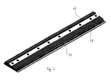
- FIG. 1 shows an alternator rotor 1 designed to be rotated about an axis X, for example at a speed of 1800 rpm, to provide a power of, for example, between 5 and 15 MW.
- the rotor 1 comprises a shaft 2 whose longitudinal axis coincides with the axis X, on which is mounted a magnetic circuit 3, which may be solid or not, this magnetic circuit comprising polar cores 4 each carrying a coil 5 formed by winding at least one electrical conductor 6.
- Each core 4 is extended by a polar expansion comprising two polar horns 7 extending longitudinally parallel to the axis X.
- Sets of fingers 8 serve to hold the heads of the coils 5, these fingers 8 can be reported or made by machining in one piece with the magnetic circuit 3.
- the rotor 1 further comprises, as can be seen more particularly in FIG. 2, between two consecutive polar nuclei 4, radiators 14 bearing respectively on insulators 16 covering the adjacent flanks of two coils 5 and serving to maintain of these.
- the radiators 14 are interconnected by two rows of threaded rods 13 which hold them against the insulators 16 and have fins 18 which contribute to the cooling of the rotor.
- the radiators 14 could still be made without fins.
- the rods 13 of one of the rows are longer than those of the other row and the screws of the two rows are offset along the longitudinal axis of the machine.
- the different screw diameters are generally offered by the manufacturers either with the standard thread ( coarse ), or with the fine pitch ( fine ) or extra fine ( extra fine ) .
- step values have been given in the table above.
- Threaded rods 13 may be finer screw pitch than the standard thread.
- at least one of the rows may include standard threaded rods.
- the distribution of the stems of each row is non-uniform along the axis of the rotor.
- the threaded rods 13 of the outer row may have a diameter different from that of the rods of the inner row, if any.
- each threaded rod 13 is transmitted to the radiators 14 by nuts 20 engaged on the rod 13, these nuts 20 resting on the radiators via washers 21. Holes are made in the radiators to receive the ends of the rods 13 extending beyond the washers 21.
- the nuts 20 are tightened with torque wrenches in order to have a relatively uniform clamping of the radiators 14 on the coils 5.
- the clamping is preferably carried out from the median region to the axial ends.
- Figure 5 shows a radiator with six blind holes that can accommodate the threaded rods.
- the number of holes can range from six to eleven, for example depending on the size of the rotor 1.
- the radiator 14 of FIG. 5 comprises two rows of fins 18, the area 24 on which are formed the holes intended to receive the threaded rods 13 having a width l of, for example, between 10 and 20 mm, for example around 14, 5 mm and a height h for example between 10 and 20 mm, for example around 17.5 mm.
- the width L of the radiator 14 may be for example between 100 and 150 mm, for example about 120 mm.
- the distance d 1 measured perpendicular to the axis of the threaded rods 13, between the inner longitudinal edge of the radiator 14 and the area 24 may be for example between 30 and 60 mm, for example equal to 44.5 mm.
- the distance d 2 measured parallel to the threaded rods 13 between the inner longitudinal edge of the radiator 14 and the area 24 may for example be between 30 and 60 mm, for example equal to 35.5 mm.
- the spacing B of the holes in the central part of the row may range from 80 to 100 mm depending on the size of the rotor 1, for example from 88 to 96 mm.
- the spacing of the holes near the axial ends of the radiator may be half of the distance in the central portion, being equal to B / 2 for example.
- the gap A between a hole located near an axial end of the radiator and the corresponding edge may range from 15 to 25 mm depending on the size of the rotor 1, for example from 19 to 24 mm.
- Examples of the values of the spacings A and B in the range 24 and the number of holes as a function of the length Lg of the radiator 14 are given in the following table: Lg AT B Number of holes 870 21 92 11 840 24 88 11 810 21 96 10 780 22 92 10 750 19 89 10 720 21 85 10 690 21 81 10 660 22 88 9 630 21 84 9 600 20 80 9 570 21 88 8 540 21 83 8 510 20 94 7 480 20 88 7 450 20 82 7 420 20 95 6
- FIG. 7 represents a radiator 14 comprising two rows of blind holes formed on two tracks 25 and 26, these rows comprising respectively three and four holes able to accommodate the threaded rods 13.
- the number of holes made in the range 25 can range, for example, from three to six, and the number of holes disposed in the range 26 can range from four to seven, depending on the size of the rotor 1.
- the width L 'of the radiator 14 may vary between 100 and 200 mm, being equal for example to 151 mm in the example of FIGS. 7 and 8.
- the width of the tracks 25 and 26 may vary between 10 and 20 mm, being for example equal to 14, 5 mm.
- the height h 1 of the range 25 may for example be between 15 and 25 mm, being for example equal to 21.5 mm.
- the height h 2 of the range 26 may be between 10 and 20 mm, being for example equal to 12 mm.
- the distance d 1 ' measured perpendicular to the threaded rods 13 between the inner longitudinal edge of the radiator 14 and the axis of the hole in the range 25 may be between 20 and 50 mm, being for example equal to 31 mm.
- the distance d 2 'measured parallel to the threaded rods 13 between the inner longitudinal edge of the radiator 14 and the axis of a hole in the range 25 may be between 30 and 50 mm, being for example equal to 43.7 mm .
- the distance d 1 '' measured perpendicularly to the threaded rods 13 between the end of the inner longitudinal edge of the radiator 14 and the axis of a hole in the range 26 may be between 40 and 80 mm, being for example equal to 61.5 mm.
- the distance d 2 '' measured on an axis perpendicular to the threaded rods 13 between the inner longitudinal edge of the radiator 14 and the axis of a hole in the range 26 may be between 80 and 120 mm, being for example equal to 106 mm.
- the distance B 'separating two holes arranged in the range 25 may vary from 130 to 190 mm depending on the size of the rotor 1 and the distance A separating a hole of an axial end of the radiator 14 can vary from 18 to 20 mm depending on the size of the rotor 1.
- the distance B 'separating the two holes from the central portion of the beach 26 may be the same as that separating two holes from the beach 25.
- the distance D between two holes located near an axial end of the rotor 1 may range from 66 to 95 mm for example, and the distance C between a hole of an axial end of the radiator 14 may vary from 18 to 20 mm according to the size of the rotor 1.
- Threaded rods can be made with a head at one end, for example.
- the threads of the threaded rods may extend only over part of their length.
- Threaded rods can be made for example with hexagonal headless screws with flat end or pointed end.
- Marking can be done at mid-length of the threaded rod for example by crushing thread or with paint, to indicate to the operator the middle of the rod and prevent the operator from bringing a bad tightening the rod to cross the radiator, which could damage the rotor.
Landscapes
- Engineering & Computer Science (AREA)
- Power Engineering (AREA)
- Iron Core Of Rotating Electric Machines (AREA)
- Insulation, Fastening Of Motor, Generator Windings (AREA)
- Manufacture Of Motors, Generators (AREA)
- Synchronous Machinery (AREA)
- Windings For Motors And Generators (AREA)
Abstract
Description
- La présente invention concerne un rotor de machine tournante électrique de forte puissance, encore appelé roue polaire.
- La publication
FR 2 842 666 - Lors de la fabrication, les tiges sont serrées une première fois à froid, puis le rotor est passé à l'étuve. Un nouveau serrage est ensuite effectué alors que la machine est encore chaude, de façon à accroître la force avec laquelle les radiateurs sont plaqués sur les bobines et assurer un bon contact thermique. Ce deuxième serrage oblige à une manutention de la machine qui peut s'avérer délicate compte tenu de son poids et de son encombrement.
- Afin de simplifier la fabrication, le deuxième serrage peut être omis mais le contact thermique est alors moins bon, amenant à réaliser la bobine avec davantage de cuivre pour réduire l'intensité de son courant donc son échauffement lors du fonctionnement, ce qui a pour inconvénient d'accroître le coût matière.
- Il existe également des rotors dans lesquels le serrage s'effectue par l'intermédiaire de rondelles Belleville. La présence de ces dernières est susceptible de nuire à la compacité de la machine et leur mise en place peut s'avérer difficile pour certaines configurations du rotor. De plus, ces rondelles sont susceptibles de perdre en élasticité lors du vieillissement de la machine, réduisant ainsi la fiabilité ou imposant une maintenance accrue.
- Il existe un besoin pour simplifier la fabrication des rotors bobinés sans que cette simplification n'entraîne une dégradation des performances thermiques ni n'amène à accroître la quantité de cuivre ou autre métal utilisé pour compenser un transfert thermique moins bon.
- La présente invention a pour objet, selon l'un de ses aspects, une machine tournante électrique comportant un rotor comprenant des pôles saillants bobinés comportant des radiateurs maintenus plaqués contre les bobines par des rangées de tiges filetées, machine dans laquelle
- au moins une rangée de tiges comporte des tiges ayant une répartition non uniforme le long de l'axe du rotor.
- Les radiateurs peuvent être plaqués fortement et précisément contre les bobines à froid et un deuxième serrage à chaud n'est plus nécessaire car la qualité du transfert thermique obtenu à froid est nettement supérieure à celle que l'on peut obtenir avec une rangée de tiges réparties uniformément le long de l'axe de rotation.
- La quantité de cuivre des bobines n'a ainsi pas à être augmentée pour compenser une dégradation du contact thermique.
- L'invention offre également une fiabilité accrue en permettant d'éviter, si cela est souhaité, l'emploi de rondelles Belleville.
- La machine peut comporter des écrous engagés sur les tiges filetées et des rondelles s'interposant entre les écrous et les radiateurs de façon à répartir l'effort de serrage sur une surface plus grande et éviter d'endommager la matière des radiateurs, lesquels peuvent être réalisés en aluminium.
- Au moins une partie des tiges peut présenter un pas de vis plus fin que le pas de vis standard.
- L'invention concerne également, selon un autre de ses aspects, une machine tournante électrique comportant un rotor comprenant des pôles saillants bobinés comportant des radiateurs maintenus plaqués contre les bobines par des tiges filetées, caractérisée par le fait qu'au moins une partie des tiges présente un pas de vis plus fin que le pas de vis standard.
- Les tiges filetées présentent par exemple un pas fin donné par le tableau suivant, en fonction du diamètre.
Ø vis (mm) 5 6 8 10 12 14 16 18 20 22 24 Pas standard 0,8 1 1,25 1,5 1,75 2 2 2,5 2,5 2,5 3 Pas fin 1 1 1,25 1,5 1,5 1,5 1,5 1,5 2 - Que les tiges soient à pas de vis standard ou à pas fin, la machine peut comporter, entre deux pôles, adjacents une rangée de tiges ou deux rangées de tiges filetées, de préférence décalées selon l'axe longitudinal de la machine, notamment une première rangée, extérieure, de tiges filetées relativement longues et une deuxième rangée, intérieure, de tiges filetées plus courtes. Le nombre de pôles est par exemple compris entre 4 et 16 ou plus.
- La première rangée comporte par exemple entre 0 et 24 tiges filetées et la deuxième rangée entre 0 et 25 tiges filetées.
- Les tiges d'au moins une rangée peuvent présenter un écartement moindre à proximité des extrémités axiales du rotor.
- En présence de deux rangées de tiges, ce sont les tiges de la rangée extérieure qui peuvent être moins écartées vers les extrémités axiales du rotor tandis que les tiges les plus courtes sont plus rapprochées entre elles vers la mi-longueur du rotor.
- Les radiateurs peuvent être identiques ou non.
- Les radiateurs peuvent comporter ou non des ailettes.
- Les radiateurs peuvent comporter des trous dans lesquels est placée la totalité ou seulement une partie des tiges filetées.
- Les radiateurs peuvent être ou non chacun d'un seul tenant. Un radiateur au moins peut comporter plusieurs parties disposées côte à côte le long de l'axe du rotor. Ces parties peuvent être ou non espacées entre elles.
- L'invention a encore pour objet un procédé de fabrication d'un rotor de machine tournante électrique comportant des pôles saillants bobinés, ces pôles saillants comprenant des bobines sur lesquelles sont maintenus plaqués des radiateurs par des rangées de tiges filetées, au moins une rangée de tiges comportant des tiges ayant une répartition non uniforme le long de l'axe du rotor, procédé dans lequel les tiges sont serrées à froid uniquement, à l'aide d'au moins une clé dynamométrique.
- Selon un tel procédé, le serrage des différentes tiges filetées peut être adapté facilement à leur emplacement sur le rotor de façon à produire un serrage permettant de plaquer le radiateur contre la bobine et cette dernière contre le noyau polaire, de manière optimale avec interposition d'isolants éventuels.
- De préférence, le serrage s'effectue d'abord dans la région médiane du rotor puis les tiges sont serrées en allant vers les extrémités axiales.
- Les vis peuvent être à pas fin ou à pas standard.
- Au sein d'une rangée, les tiges successives peuvent être alignées ou non avec les tiges qui précèdent. Les tiges peuvent être disposées en quinconce, le cas échéant.
- L'invention pourra être mieux comprise à la lecture de la description détaillée qui va suivre, d'un exemple de mise en oeuvre non limitatif de celle-ci, et à l'examen du dessin annexé, sur lequel :
- la figure 1 représente de manière schématique, en perspective, un rotor conforme à l'invention,
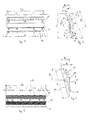
- la figure 2 est une vue axiale, schématique et partielle, d'un détail de réalisation du rotor,
- les figures 3 et 4 représentent, en perspective, des exemples de radiateurs conformes à l'invention, comportant respectivement une ou deux rangées de trous pouvant accueillir les tiges filetées,
- les figures 5 et 7 sont des vues de face de deux radiateurs conformes à l'invention, comportant respectivement une et deux rangées de trous pouvant accueillir les tiges filetées,
- la figure 6 est une coupe transversale, schématique et partielle, du radiateur de la figure 5, et
- la figure 8 est une coupe transversale, schématique et partielle, du radiateur de la figure 7.
- On a représenté sur la figure 1 un rotor 1 d'alternateur destiné à être entraîné en rotation autour d'un axe X, par exemple à une vitesse de 1800 tr/mn, pour fournir une puissance comprise par exemple entre 5 et 15 MW.
- Le rotor 1 comporte un arbre 2, dont l'axe longitudinal coïncide avec l'axe X, sur lequel est monté un circuit magnétique 3, qui peut être massif ou non, ce circuit magnétique comportant des noyaux polaires 4 portant chacun une bobine 5 formée par l'enroulement d'au moins un conducteur électrique 6.
- Chaque noyau 4 est prolongé par un épanouissement polaire comportant deux cornes polaires 7 s'étendant longitudinalement parallèlement à l'axe X.
- Des ensembles de doigts 8 servent à maintenir les têtes des bobines 5, ces doigts 8 pouvant être rapportés ou réalisés par usinage d'un seul tenant avec le circuit magnétique 3.
- Le rotor 1 comporte, en outre, comme on peut le voir plus particulièrement sur la figure 2, entre deux noyaux polaires 4 consécutifs, des radiateurs 14 venant en appui respectivement sur des isolants 16 recouvrant les flancs adjacents de deux bobines 5 et servant au maintien de celles-ci.
- Les radiateurs 14 sont reliés entre eux par deux rangées de tiges filetées 13 qui les maintiennent contre les isolants 16 et comportent des ailettes 18 qui contribuent au refroidissement du rotor. Les radiateurs 14 pourraient encore être réalisés sans ailettes.
- Les tiges 13 de l'une des rangées sont plus longues que celles de l'autre rangée et les vis des deux rangées sont décalées selon l'axe longitudinal de la machine.
- Les différents diamètres de vis sont généralement proposés par les fabricants soit avec le pas de vis standard (coarse), soit avec le pas fin (fine) ou extra-fin (extra fine).
- Des exemples de valeurs de pas ont été donnés dans le tableau plus haut.
- Les tiges filetées 13 peuvent être à pas de vis plus fin que le pas de vis standard. En variante, au moins l'une des rangées peut comporter des tiges à pas de vis standard.
- La répartition des tiges de chaque rangée est non uniforme le long de l'axe du rotor.
- Les tiges filetées 13 de la rangée extérieure peuvent présenter un diamètre différent de celui des tiges de la rangée intérieure, le cas échéant.
- La force de serrage de chaque tige filetée 13 est transmise aux radiateurs 14 par des écrous 20 engagés sur la tige 13, ces écrous 20 s'appuyant sur les radiateurs par l'intermédiaire de rondelles 21. Des trous sont réalisés dans les radiateurs pour recevoir les extrémités des tiges 13 s'étendant au-delà des rondelles 21.
- Lors de la fabrication de la machine, les écrous 20 sont serrés à l'aide de clés dynamométriques afin d'avoir un serrage relativement uniforme des radiateurs 14 sur les bobines 5. Le serrage est de préférence effectué à partir de la région médiane vers les extrémités axiales.
- Lorsque les vis sont à pas fin, le serrage peut être plus précis et de meilleure qualité qu'avec les tiges à pas de vis standard.
- La figure 5 représente un radiateur comportant six trous borgnes pouvant accueillir les tiges filetées. Le nombre de trous peut aller de six à onze, par exemple en fonction de la dimension du rotor 1.
- Le radiateur 14 de la figure 5 comporte deux rangées d'ailettes 18, la plage 24 sur laquelle sont formés les trous destinés à accueillir les tiges filetées 13 ayant une largeur l comprise par exemple entre 10 et 20 mm, par exemple voisine de 14,5 mm et une hauteur h comprise par exemple entre 10 et 20 mm, par exemple voisine de 17,5 mm.
- La largeur L du radiateur 14 peut être comprise par exemple entre 100 et 150 mm, par exemple voisine de 120 mm.
- La distance d1, mesurée perpendiculairement à l'axe des tiges filetées 13, entre le bord longitudinal interne du radiateur 14 et la plage 24 peut être comprise par exemple entre 30 et 60 mm, par exemple égale à 44,5 mm. De plus, la distance d2 mesurée parallèlement aux tiges filetées 13 entre le bord longitudinal interne du radiateur 14 et la plage 24 peut être par exemple comprise entre 30 et 60 mm, par exemple égale à 35, 5 mm.
- L'écartement B des trous dans la partie centrale de la rangée peut aller de 80 à 100 mm en fonction de la dimension du rotor 1, par exemple de 88 à 96 mm.
- Dans l'exemple considéré, l'écartement des trous à proximité des extrémités axiales du radiateur peut être deux fois moins important que l'écartement en partie centrale, étant égal à B/2 par exemple.
- Par ailleurs, l'écartement A entre un trou situé à proximité d'une extrémité axiale du radiateur et le bord correspondant peut aller de 15 à 25 mm en fonction de la dimension du rotor 1, par exemple de 19 à 24 mm.
- Des exemples de valeur des écartements A et B dans la plage 24 et du nombre de trous en fonction de la longueur Lg du radiateur 14 sont donnés dans le tableau suivant :
Lg A B Nombre de trous 870 21 92 11 840 24 88 11 810 21 96 10 780 22 92 10 750 19 89 10 720 21 85 10 690 21 81 10 660 22 88 9 630 21 84 9 600 20 80 9 570 21 88 8 540 21 83 8 510 20 94 7 480 20 88 7 450 20 82 7 420 20 95 6 - La figure 7 représente un radiateur 14 comportant deux rangées de trous borgnes ménagées sur deux plages 25 et 26, ces rangées comportant respectivement trois et quatre trous pouvant accueillir les tiges filetées 13.
- Le nombre de trous réalisés sur la plage 25 peut aller par exemple de trois à six et le nombre de trous disposés sur la plage 26 peut aller de quatre à sept, en fonction de la dimension du rotor 1.
- La largeur L' du radiateur 14 peut varier entre 100 et 200 mm, étant égale par exemple à 151 mm dans l'exemple des figures 7 et 8.
- La largeur l' des plages 25 et 26 peut varier entre 10 et 20 mm, étant par exemple égale à 14, 5 mm. La hauteur h1 de la plage 25 peut par exemple être comprise entre 15 et 25 mm, étant par exemple égale à 21,5 mm. La hauteur h2 de la plage 26 peut être comprise entre 10 et 20 mm, étant par exemple égale à 12 mm.
- La distance d1' mesurée perpendiculairement aux tiges filetées 13 entre le bord longitudinal interne du radiateur 14 et l'axe du trou situé sur la plage 25 peut être comprise entre 20 et 50 mm, étant par exemple égale à 31 mm. La distance d2 ' mesurée parallèlement aux tiges filetées 13 entre le bord longitudinal interne du radiateur 14 et l'axe d'un trou situé sur la plage 25 peut être comprise entre 30 et 50 mm, étant par exemple égale à 43,7 mm.
- La distance d1'' mesurée perpendiculairement aux tiges filetées 13 entre l'extrémité du bord longitudinal interne du radiateur 14 et l'axe d'un trou situé sur la plage 26 peut être comprise entre 40 et 80 mm, étant par exemple égale à 61,5 mm. La distance d2'' mesurée sur un axe perpendiculairement aux tiges filetées 13 entre le bord longitudinal interne du radiateur 14 et l'axe d'un trou situé sur la plage 26 peut être comprise entre 80 et 120 mm, étant par exemple égale à 106 mm.
- Dans l'exemple considéré, la distance B' séparant deux trous disposés sur la plage 25 peut varier de 130 à 190 mm en fonction de la dimension du rotor 1 et la distance A' séparant un trou d'une extrémité axiale du radiateur 14 peut varier de 18 à 20 mm en fonction de la dimension du rotor 1.
- La distance B' séparant les deux trous de la partie centrale de la plage 26 peut être la même que celle séparant deux trous de la plage 25.
- La distance D séparant deux trous situés à proximité d'une extrémité axiale du rotor 1 peut aller de 66 à 95 mm par exemple, et la distance C séparant un trou d'une extrémité axiale du radiateur 14 peut varier de 18 à 20 mm selon la dimension du rotor 1.
- Des exemples de valeurs des écartements A', B', C, D et du nombre de trous des plages 25 et 26 en fonction de la longueur Lg du radiateur 14 sont donnés dans le tableau suivant :
Lg A' B' C D Nombre de trous plage 25 Nombre de trous plage 26 750 20 142 20 71 6 7 720 20 136 20 68 6 7 690 19 163 19 81,5 5 6 660 20 155 20 77,5 5 6 630 19 148 19 74 5 6 600 20 140 20 70 5 6 570 19 133 19 66 ?5 5 6 540 18 168 18 84 4 5 510 18 158 18 79 4 5 480 18 148 18 74 4 5 450 18 138 18 69 4 5 420 20 190 20 95 3 4 390 19 176 19 88 3 4 360 20 160 20 80 3 4 - L'invention n'est pas limitée aux exemples qui viennent d'être décrits. Les tiges filetées peuvent être réalisées avec une tête à une extrémité, par exemple. Le filetage des tiges filetées peut ne s'étendre que sur une partie de leur longueur. Les tiges filetées peuvent être réalisées par exemple avec des vis sans tête six pans creuses à bout plat ou à bout pointu.
- Un marquage peut être effectué à mi-longueur de la tige filetée par exemple par un écrasement de filetage ou avec de la peinture, afin d'indiquer à l'opérateur le milieu de la tige et éviter que l'opérateur n'amène par un mauvais serrage la tige à traverser le radiateur, ce qui pourrait endommager le rotor.
- L'expression « comportant un » doit être comprise comme étant synonyme de « comportant au moins un », sauf si le contraire est spécifié.
Claims (14)
- Machine tournante électrique (1) comportant un rotor comprenant des pôles saillants bobinés comportant des radiateurs (14) maintenus plaqués contre les bobines (5) par des rangées de tiges filetées (13), caractérisée par le fait qu'au moins une rangée de tiges (13) comporte des tiges ayant une répartition non uniforme le long de l'axe du rotor.
- Machine selon la revendication 1, caractérisée par le fait qu'au moins une partie des tiges (13) présente un pas de vis plus fin que le pas de vis standard.
- Machine selon la revendication 2, dans laquelle toutes les tiges (13) présentent un pas de vis plus fin que le pas de vis standard.
- Machine selon la revendication 3, les tiges filetées (13) présentant un diamètre choisi parmi 5, 6, 8, 10, 12, 14, 16, 18, 20, 22, 24 mm et des pas de vis respectivement inférieurs à 0,8 ; 1 ; 1,25 ; 1,5 ; 1,75 ; 2 ; 2 ; 2,5 ; 2,5 ; 2,5 ; 3 mm.
- Machine selon l'une quelconque des revendications précédentes, comportant des écrous (20) engagés sur les tiges (13) et des rondelles (21) s'interposant entre les écrous et les radiateurs (14).
- Machine selon l'une quelconque des revendications précédentes, comportant entre deux pôles adjacents deux rangées de tiges filetées (13) décalées selon l'axe longitudinal (X) de la machine.
- Machine selon la revendication 6, comportant entre deux pôles adjacents une première rangée, extérieure, de tiges filetées relativement longues et une deuxième rangée, intérieure, de tiges filetées plus courtes.
- Machine selon l'une quelconque des revendications précédentes, la répartition des tiges de chaque rangée étant non uniforme le long de l'axe du rotor.
- Machine selon l'une quelconque des revendications précédentes, au moins une rangée présentant un écartement entre les tiges qui est moindre à proximité des extrémités axiales du rotor.
- Machine selon la revendication 7, les tiges de la rangée extérieure étant moins écartées vers les extrémités axiales du rotor.
- Machine selon l'une quelconque des revendications précédentes, les tiges filetées présentant un marquage à mi-longueur.
- Machine tournante électrique (1) comportant un rotor comprenant des pôles saillants bobinés comportant des radiateurs (14) maintenus plaqués contre les bobines (5) par des tiges filetées (13), caractérisée par le fait qu'au moins une partie des tiges (13) présente un pas de vis plus fin que le pas de vis standard.
- Procédé de fabrication d'un rotor de machine tournante électrique comportant des pôles saillants bobinés, ces pôles saillants comprenant des bobines (5) sur lesquelles sont maintenus plaqués des radiateurs (14) par des rangées de tiges filetées (13), au moins une rangée de tiges comportant des tiges ayant une répartition non uniforme le long de l'axe du rotor, les tiges étant serrées à froid uniquement, à l'aide d'au moins une clé dynamométrique.
- Procédé selon la revendication précédente, le serrage s'effectuant d'abord dans la région médiane du rotor puis les tiges étant serrées en allant vers les extrémités axiales.
Applications Claiming Priority (1)
| Application Number | Priority Date | Filing Date | Title |
|---|---|---|---|
| FR0652794A FR2903536B1 (fr) | 2006-07-04 | 2006-07-04 | Rotor de machine electrique |
Publications (2)
| Publication Number | Publication Date |
|---|---|
| EP1876686A1 true EP1876686A1 (fr) | 2008-01-09 |
| EP1876686B1 EP1876686B1 (fr) | 2009-06-24 |
Family
ID=37764006
Family Applications (1)
| Application Number | Title | Priority Date | Filing Date |
|---|---|---|---|
| EP07301203A Not-in-force EP1876686B1 (fr) | 2006-07-04 | 2007-07-03 | Rotor de machine électrique |
Country Status (4)
| Country | Link |
|---|---|
| EP (1) | EP1876686B1 (fr) |
| AT (1) | ATE434855T1 (fr) |
| DE (1) | DE602007001365D1 (fr) |
| FR (1) | FR2903536B1 (fr) |
Cited By (1)
| Publication number | Priority date | Publication date | Assignee | Title |
|---|---|---|---|---|
| WO2010079455A2 (fr) | 2009-01-07 | 2010-07-15 | Moteurs Leroy-Somer | Rotors des machines tournantes electriques |
Citations (7)
| Publication number | Priority date | Publication date | Assignee | Title |
|---|---|---|---|---|
| US3766417A (en) * | 1972-08-11 | 1973-10-16 | Gen Electric | Side support for synchronous rotor field winding |
| DE2226078A1 (de) * | 1972-05-29 | 1973-12-13 | Unelec | Elektrische wicklung |
| GB1393025A (en) | 1972-05-18 | 1975-05-07 | Unelec | Electrical machine salient pole rotors |
| US4554475A (en) * | 1982-02-25 | 1985-11-19 | Century Electric, Inc. | Field coil air vents for dynamoelectric machine |
| DE8803135U1 (de) * | 1988-03-04 | 1989-07-06 | Siemens AG, 1000 Berlin und 8000 München | Elektrische Maschine mit ausgeprägten Polen |
| US6054790A (en) * | 1999-03-23 | 2000-04-25 | Emerson Electric Co. | V-block arrangement for a dynamo-electric machine |
| FR2842666A1 (fr) * | 2002-07-22 | 2004-01-23 | Leroy Somer Moteurs | Machine electrique tournante comportante un rotor ayant un circuit magnetique massif |
-
2006
- 2006-07-04 FR FR0652794A patent/FR2903536B1/fr not_active Expired - Fee Related
-
2007
- 2007-07-03 EP EP07301203A patent/EP1876686B1/fr not_active Not-in-force
- 2007-07-03 DE DE602007001365T patent/DE602007001365D1/de active Active
- 2007-07-03 AT AT07301203T patent/ATE434855T1/de not_active IP Right Cessation
Patent Citations (7)
| Publication number | Priority date | Publication date | Assignee | Title |
|---|---|---|---|---|
| GB1393025A (en) | 1972-05-18 | 1975-05-07 | Unelec | Electrical machine salient pole rotors |
| DE2226078A1 (de) * | 1972-05-29 | 1973-12-13 | Unelec | Elektrische wicklung |
| US3766417A (en) * | 1972-08-11 | 1973-10-16 | Gen Electric | Side support for synchronous rotor field winding |
| US4554475A (en) * | 1982-02-25 | 1985-11-19 | Century Electric, Inc. | Field coil air vents for dynamoelectric machine |
| DE8803135U1 (de) * | 1988-03-04 | 1989-07-06 | Siemens AG, 1000 Berlin und 8000 München | Elektrische Maschine mit ausgeprägten Polen |
| US6054790A (en) * | 1999-03-23 | 2000-04-25 | Emerson Electric Co. | V-block arrangement for a dynamo-electric machine |
| FR2842666A1 (fr) * | 2002-07-22 | 2004-01-23 | Leroy Somer Moteurs | Machine electrique tournante comportante un rotor ayant un circuit magnetique massif |
Cited By (2)
| Publication number | Priority date | Publication date | Assignee | Title |
|---|---|---|---|---|
| WO2010079455A2 (fr) | 2009-01-07 | 2010-07-15 | Moteurs Leroy-Somer | Rotors des machines tournantes electriques |
| US8274185B2 (en) | 2009-01-07 | 2012-09-25 | Moteurs Leroy-Somer | Rotors for electric rotary machines |
Also Published As
| Publication number | Publication date |
|---|---|
| DE602007001365D1 (de) | 2009-08-06 |
| FR2903536A1 (fr) | 2008-01-11 |
| ATE434855T1 (de) | 2009-07-15 |
| EP1876686B1 (fr) | 2009-06-24 |
| FR2903536B1 (fr) | 2008-09-26 |
Similar Documents
| Publication | Publication Date | Title |
|---|---|---|
| EP3627659B1 (fr) | Rotor pour machine electrique asynchrone a arbre non traversant | |
| EP3641106B1 (fr) | Machine tournante electrique | |
| EP2332232B1 (fr) | Stator pour machine électrique tournante et son procédé de fabrication | |
| EP2983272B1 (fr) | Induit de machine électrique tournante à performances magnétiques améliorées | |
| EP4111822A1 (fr) | Dispositif de chauffage d'un produit par induction a flux transverse | |
| EP1876686B1 (fr) | Rotor de machine électrique | |
| EP2297838B1 (fr) | Rotor d'une machine electrique synchrone multipolaire a poles saillants | |
| US8572837B2 (en) | Method for making an efficient rotor for an electric motor | |
| EP2239828A2 (fr) | Bobine pour une machine électrique tournante | |
| WO2016016558A2 (fr) | Stator ameliore et machine électrique comportant un tel stator | |
| FR3127343A1 (fr) | Stator pour machine électrique à flux axial | |
| WO2016199077A1 (fr) | Dispositif de connexion électrique entre un moteur électrique et une unité d'alimentation dudit moteur, notamment pour compresseur de véhicule automobile | |
| EP4128485A1 (fr) | Dispositif de connexion pour stator | |
| FR3009141A1 (fr) | Stator bobine a remplissage d'encoches optimise et machine electrique correspondante | |
| FR3066659A1 (fr) | Machine electrique tournante munie d'un palier ayant une face interne configuree pour ameliorer le refroidissement | |
| WO2020094574A1 (fr) | Rotor a cage d'ecureuil et machine electrique asynchrone comprotant un tel rotor | |
| FR2538970A1 (fr) | Circuit magnetique pour machine electrique a poles saillants | |
| EP3534500A1 (fr) | Rotor ou stator bobine et procede de fabrication | |
| EP3895295B1 (fr) | Barre conductrice, rotor et machine électrique tournante associés | |
| WO2014140477A1 (fr) | Rotor de machine électrique muni d'au moins une frette de maintien des chignons du bobinage et machine électrique correspondante | |
| WO2020120662A1 (fr) | Rotor pour machine electrique tournante asynchrone a cage d'ecureuil et machine tournante associee | |
| FR3018642A1 (fr) | Machine electrique tournante | |
| FR2971375A3 (fr) | Plaque de calage pour un rotor a poles saillants | |
| FR3064841A1 (fr) | Machine electrique tournante a configuration modifiee pour faciliter la montabilite d'un element fonctionnel | |
| FR3059170A1 (fr) | Roue polaire d'inducteur de machine electrique tournante |
Legal Events
| Date | Code | Title | Description |
|---|---|---|---|
| PUAI | Public reference made under article 153(3) epc to a published international application that has entered the european phase |
Free format text: ORIGINAL CODE: 0009012 |
|
| AK | Designated contracting states |
Kind code of ref document: A1 Designated state(s): AT BE BG CH CY CZ DE DK EE ES FI FR GB GR HU IE IS IT LI LT LU LV MC MT NL PL PT RO SE SI SK TR |
|
| AX | Request for extension of the european patent |
Extension state: AL BA HR MK YU |
|
| 17P | Request for examination filed |
Effective date: 20080225 |
|
| 17Q | First examination report despatched |
Effective date: 20080424 |
|
| AKX | Designation fees paid |
Designated state(s): AT BE BG CH CY CZ DE DK EE ES FI FR GB GR HU IE IS IT LI LT LU LV MC MT NL PL PT RO SE SI SK TR |
|
| GRAP | Despatch of communication of intention to grant a patent |
Free format text: ORIGINAL CODE: EPIDOSNIGR1 |
|
| GRAS | Grant fee paid |
Free format text: ORIGINAL CODE: EPIDOSNIGR3 |
|
| GRAA | (expected) grant |
Free format text: ORIGINAL CODE: 0009210 |
|
| AK | Designated contracting states |
Kind code of ref document: B1 Designated state(s): AT BE BG CH CY CZ DE DK EE ES FI FR GB GR HU IE IS IT LI LT LU LV MC MT NL PL PT RO SE SI SK TR |
|
| REG | Reference to a national code |
Ref country code: GB Ref legal event code: FG4D Free format text: NOT ENGLISH |
|
| REG | Reference to a national code |
Ref country code: CH Ref legal event code: EP |
|
| REG | Reference to a national code |
Ref country code: IE Ref legal event code: FG4D Free format text: LANGUAGE OF EP DOCUMENT: FRENCH |
|
| REF | Corresponds to: |
Ref document number: 602007001365 Country of ref document: DE Date of ref document: 20090806 Kind code of ref document: P |
|
| REG | Reference to a national code |
Ref country code: RO Ref legal event code: EPE |
|
| PG25 | Lapsed in a contracting state [announced via postgrant information from national office to epo] |
Ref country code: AT Free format text: LAPSE BECAUSE OF FAILURE TO SUBMIT A TRANSLATION OF THE DESCRIPTION OR TO PAY THE FEE WITHIN THE PRESCRIBED TIME-LIMIT Effective date: 20090624 Ref country code: FI Free format text: LAPSE BECAUSE OF FAILURE TO SUBMIT A TRANSLATION OF THE DESCRIPTION OR TO PAY THE FEE WITHIN THE PRESCRIBED TIME-LIMIT Effective date: 20090624 Ref country code: LT Free format text: LAPSE BECAUSE OF FAILURE TO SUBMIT A TRANSLATION OF THE DESCRIPTION OR TO PAY THE FEE WITHIN THE PRESCRIBED TIME-LIMIT Effective date: 20090624 |
|
| PG25 | Lapsed in a contracting state [announced via postgrant information from national office to epo] |
Ref country code: PL Free format text: LAPSE BECAUSE OF FAILURE TO SUBMIT A TRANSLATION OF THE DESCRIPTION OR TO PAY THE FEE WITHIN THE PRESCRIBED TIME-LIMIT Effective date: 20090624 Ref country code: SE Free format text: LAPSE BECAUSE OF FAILURE TO SUBMIT A TRANSLATION OF THE DESCRIPTION OR TO PAY THE FEE WITHIN THE PRESCRIBED TIME-LIMIT Effective date: 20090924 Ref country code: LV Free format text: LAPSE BECAUSE OF FAILURE TO SUBMIT A TRANSLATION OF THE DESCRIPTION OR TO PAY THE FEE WITHIN THE PRESCRIBED TIME-LIMIT Effective date: 20090624 Ref country code: SI Free format text: LAPSE BECAUSE OF FAILURE TO SUBMIT A TRANSLATION OF THE DESCRIPTION OR TO PAY THE FEE WITHIN THE PRESCRIBED TIME-LIMIT Effective date: 20090624 |
|
| NLV1 | Nl: lapsed or annulled due to failure to fulfill the requirements of art. 29p and 29m of the patents act | ||
| PG25 | Lapsed in a contracting state [announced via postgrant information from national office to epo] |
Ref country code: IS Free format text: LAPSE BECAUSE OF FAILURE TO SUBMIT A TRANSLATION OF THE DESCRIPTION OR TO PAY THE FEE WITHIN THE PRESCRIBED TIME-LIMIT Effective date: 20091024 Ref country code: ES Free format text: LAPSE BECAUSE OF FAILURE TO SUBMIT A TRANSLATION OF THE DESCRIPTION OR TO PAY THE FEE WITHIN THE PRESCRIBED TIME-LIMIT Effective date: 20091005 Ref country code: EE Free format text: LAPSE BECAUSE OF FAILURE TO SUBMIT A TRANSLATION OF THE DESCRIPTION OR TO PAY THE FEE WITHIN THE PRESCRIBED TIME-LIMIT Effective date: 20090624 |
|
| BERE | Be: lapsed |
Owner name: MOTEURS LEROY-SOMER Effective date: 20090731 |
|
| REG | Reference to a national code |
Ref country code: IE Ref legal event code: FD4D |
|
| PG25 | Lapsed in a contracting state [announced via postgrant information from national office to epo] |
Ref country code: NL Free format text: LAPSE BECAUSE OF FAILURE TO SUBMIT A TRANSLATION OF THE DESCRIPTION OR TO PAY THE FEE WITHIN THE PRESCRIBED TIME-LIMIT Effective date: 20090624 Ref country code: MC Free format text: LAPSE BECAUSE OF NON-PAYMENT OF DUE FEES Effective date: 20090731 Ref country code: SK Free format text: LAPSE BECAUSE OF FAILURE TO SUBMIT A TRANSLATION OF THE DESCRIPTION OR TO PAY THE FEE WITHIN THE PRESCRIBED TIME-LIMIT Effective date: 20090624 |
|
| PG25 | Lapsed in a contracting state [announced via postgrant information from national office to epo] |
Ref country code: BG Free format text: LAPSE BECAUSE OF FAILURE TO SUBMIT A TRANSLATION OF THE DESCRIPTION OR TO PAY THE FEE WITHIN THE PRESCRIBED TIME-LIMIT Effective date: 20090924 Ref country code: PT Free format text: LAPSE BECAUSE OF FAILURE TO SUBMIT A TRANSLATION OF THE DESCRIPTION OR TO PAY THE FEE WITHIN THE PRESCRIBED TIME-LIMIT Effective date: 20091024 |
|
| PG25 | Lapsed in a contracting state [announced via postgrant information from national office to epo] |
Ref country code: DK Free format text: LAPSE BECAUSE OF FAILURE TO SUBMIT A TRANSLATION OF THE DESCRIPTION OR TO PAY THE FEE WITHIN THE PRESCRIBED TIME-LIMIT Effective date: 20090624 Ref country code: IE Free format text: LAPSE BECAUSE OF FAILURE TO SUBMIT A TRANSLATION OF THE DESCRIPTION OR TO PAY THE FEE WITHIN THE PRESCRIBED TIME-LIMIT Effective date: 20090624 |
|
| PLBE | No opposition filed within time limit |
Free format text: ORIGINAL CODE: 0009261 |
|
| STAA | Information on the status of an ep patent application or granted ep patent |
Free format text: STATUS: NO OPPOSITION FILED WITHIN TIME LIMIT |
|
| 26N | No opposition filed |
Effective date: 20100325 |
|
| PG25 | Lapsed in a contracting state [announced via postgrant information from national office to epo] |
Ref country code: BE Free format text: LAPSE BECAUSE OF NON-PAYMENT OF DUE FEES Effective date: 20090731 |
|
| REG | Reference to a national code |
Ref country code: FR Ref legal event code: ST Effective date: 20100531 |
|
| REG | Reference to a national code |
Ref country code: FR Ref legal event code: RN |
|
| PG25 | Lapsed in a contracting state [announced via postgrant information from national office to epo] |
Ref country code: FR Free format text: LAPSE BECAUSE OF NON-PAYMENT OF DUE FEES Effective date: 20090824 |
|
| REG | Reference to a national code |
Ref country code: FR Ref legal event code: FC |
|
| PGFP | Annual fee paid to national office [announced via postgrant information from national office to epo] |
Ref country code: CZ Payment date: 20100611 Year of fee payment: 4 |
|
| PG25 | Lapsed in a contracting state [announced via postgrant information from national office to epo] |
Ref country code: GR Free format text: LAPSE BECAUSE OF FAILURE TO SUBMIT A TRANSLATION OF THE DESCRIPTION OR TO PAY THE FEE WITHIN THE PRESCRIBED TIME-LIMIT Effective date: 20090925 |
|
| PGFP | Annual fee paid to national office [announced via postgrant information from national office to epo] |
Ref country code: RO Payment date: 20100628 Year of fee payment: 4 |
|
| PGRI | Patent reinstated in contracting state [announced from national office to epo] |
Ref country code: FR Effective date: 20100723 |
|
| PGFP | Annual fee paid to national office [announced via postgrant information from national office to epo] |
Ref country code: FR Payment date: 20100809 Year of fee payment: 4 |
|
| PGFP | Annual fee paid to national office [announced via postgrant information from national office to epo] |
Ref country code: DE Payment date: 20100923 Year of fee payment: 4 |
|
| PG25 | Lapsed in a contracting state [announced via postgrant information from national office to epo] |
Ref country code: LU Free format text: LAPSE BECAUSE OF NON-PAYMENT OF DUE FEES Effective date: 20090703 Ref country code: MT Free format text: LAPSE BECAUSE OF FAILURE TO SUBMIT A TRANSLATION OF THE DESCRIPTION OR TO PAY THE FEE WITHIN THE PRESCRIBED TIME-LIMIT Effective date: 20090624 |
|
| PG25 | Lapsed in a contracting state [announced via postgrant information from national office to epo] |
Ref country code: HU Free format text: LAPSE BECAUSE OF FAILURE TO SUBMIT A TRANSLATION OF THE DESCRIPTION OR TO PAY THE FEE WITHIN THE PRESCRIBED TIME-LIMIT Effective date: 20091225 |
|
| PG25 | Lapsed in a contracting state [announced via postgrant information from national office to epo] |
Ref country code: TR Free format text: LAPSE BECAUSE OF FAILURE TO SUBMIT A TRANSLATION OF THE DESCRIPTION OR TO PAY THE FEE WITHIN THE PRESCRIBED TIME-LIMIT Effective date: 20090624 |
|
| PG25 | Lapsed in a contracting state [announced via postgrant information from national office to epo] |
Ref country code: CY Free format text: LAPSE BECAUSE OF FAILURE TO SUBMIT A TRANSLATION OF THE DESCRIPTION OR TO PAY THE FEE WITHIN THE PRESCRIBED TIME-LIMIT Effective date: 20090624 |
|
| PGFP | Annual fee paid to national office [announced via postgrant information from national office to epo] |
Ref country code: IT Payment date: 20100731 Year of fee payment: 4 |
|
| PG25 | Lapsed in a contracting state [announced via postgrant information from national office to epo] |
Ref country code: CZ Free format text: LAPSE BECAUSE OF NON-PAYMENT OF DUE FEES Effective date: 20110703 |
|
| REG | Reference to a national code |
Ref country code: CH Ref legal event code: PL |
|
| GBPC | Gb: european patent ceased through non-payment of renewal fee |
Effective date: 20110703 |
|
| REG | Reference to a national code |
Ref country code: FR Ref legal event code: ST Effective date: 20120330 |
|
| PG25 | Lapsed in a contracting state [announced via postgrant information from national office to epo] |
Ref country code: DE Free format text: LAPSE BECAUSE OF NON-PAYMENT OF DUE FEES Effective date: 20120201 Ref country code: CH Free format text: LAPSE BECAUSE OF NON-PAYMENT OF DUE FEES Effective date: 20110731 Ref country code: FR Free format text: LAPSE BECAUSE OF NON-PAYMENT OF DUE FEES Effective date: 20110801 Ref country code: LI Free format text: LAPSE BECAUSE OF NON-PAYMENT OF DUE FEES Effective date: 20110731 |
|
| REG | Reference to a national code |
Ref country code: DE Ref legal event code: R119 Ref document number: 602007001365 Country of ref document: DE Effective date: 20120201 |
|
| PG25 | Lapsed in a contracting state [announced via postgrant information from national office to epo] |
Ref country code: IT Free format text: LAPSE BECAUSE OF NON-PAYMENT OF DUE FEES Effective date: 20110703 |
|
| PG25 | Lapsed in a contracting state [announced via postgrant information from national office to epo] |
Ref country code: GB Free format text: LAPSE BECAUSE OF NON-PAYMENT OF DUE FEES Effective date: 20110703 |
|
| PG25 | Lapsed in a contracting state [announced via postgrant information from national office to epo] |
Ref country code: RO Free format text: LAPSE BECAUSE OF NON-PAYMENT OF DUE FEES Effective date: 20110703 |