EP1876741A1 - Vorrichtung und verfahren zur drahtlosen kommunikation - Google Patents
Vorrichtung und verfahren zur drahtlosen kommunikation Download PDFInfo
- Publication number
- EP1876741A1 EP1876741A1 EP06714696A EP06714696A EP1876741A1 EP 1876741 A1 EP1876741 A1 EP 1876741A1 EP 06714696 A EP06714696 A EP 06714696A EP 06714696 A EP06714696 A EP 06714696A EP 1876741 A1 EP1876741 A1 EP 1876741A1
- Authority
- EP
- European Patent Office
- Prior art keywords
- subcarriers
- wireless communication
- subcarrier
- spread
- received power
- Prior art date
- Legal status (The legal status is an assumption and is not a legal conclusion. Google has not performed a legal analysis and makes no representation as to the accuracy of the status listed.)
- Withdrawn
Links
Images









Classifications
-
- H—ELECTRICITY
- H04—ELECTRIC COMMUNICATION TECHNIQUE
- H04J—MULTIPLEX COMMUNICATION
- H04J13/00—Code division multiplex systems
- H04J13/10—Code generation
-
- H—ELECTRICITY
- H04—ELECTRIC COMMUNICATION TECHNIQUE
- H04L—TRANSMISSION OF DIGITAL INFORMATION, e.g. TELEGRAPHIC COMMUNICATION
- H04L27/00—Modulated-carrier systems
- H04L27/26—Systems using multi-frequency codes
- H04L27/2601—Multicarrier modulation systems
- H04L27/2614—Peak power aspects
- H04L27/2615—Reduction thereof using coding
-
- H—ELECTRICITY
- H04—ELECTRIC COMMUNICATION TECHNIQUE
- H04L—TRANSMISSION OF DIGITAL INFORMATION, e.g. TELEGRAPHIC COMMUNICATION
- H04L5/00—Arrangements affording multiple use of the transmission path
- H04L5/003—Arrangements for allocating sub-channels of the transmission path
- H04L5/0044—Allocation of payload; Allocation of data channels, e.g. PDSCH or PUSCH
- H04L5/0046—Determination of the number of bits transmitted on different sub-channels
-
- H—ELECTRICITY
- H04—ELECTRIC COMMUNICATION TECHNIQUE
- H04L—TRANSMISSION OF DIGITAL INFORMATION, e.g. TELEGRAPHIC COMMUNICATION
- H04L5/00—Arrangements affording multiple use of the transmission path
- H04L5/003—Arrangements for allocating sub-channels of the transmission path
- H04L5/0058—Allocation criteria
- H04L5/006—Quality of the received signal, e.g. BER, SNR, water filling
-
- H—ELECTRICITY
- H04—ELECTRIC COMMUNICATION TECHNIQUE
- H04L—TRANSMISSION OF DIGITAL INFORMATION, e.g. TELEGRAPHIC COMMUNICATION
- H04L5/00—Arrangements affording multiple use of the transmission path
- H04L5/0001—Arrangements for dividing the transmission path
- H04L5/0014—Three-dimensional division
- H04L5/0016—Time-frequency-code
- H04L5/0021—Time-frequency-code in which codes are applied as a frequency-domain sequences, e.g. MC-CDMA
-
- H—ELECTRICITY
- H04—ELECTRIC COMMUNICATION TECHNIQUE
- H04L—TRANSMISSION OF DIGITAL INFORMATION, e.g. TELEGRAPHIC COMMUNICATION
- H04L5/00—Arrangements affording multiple use of the transmission path
- H04L5/003—Arrangements for allocating sub-channels of the transmission path
- H04L5/0048—Allocation of pilot signals, i.e. of signals known to the receiver
Definitions
- the present invention relates to a wireless communication apparatus and a wireless communication method that perform a wireless communication by combining a multicarrier transmission system with a spread spectrum.
- MC-CDMA Multicarrier CDMA
- MC-CDMA Multicarrier CDMA
- a transmitter 150 data to be transmitted is added with an error correcting code by a coding part 151 and modulated by a modulation part 152.
- a multiplexing part (Mux part) 153 multiplexes the modulated data parallel-converted into as many portions as the number of subcarriers with a pilot signal used by a receiving side for estimating received SIR. Then, an S/P conversion part 154 converts the data into parallel signals. Further, each signal is copied by a copying part 155 to generate a plurality of signals.
- the number of copied signals is equal to a spreading factor. That is, if the spreading factor is 16, for example, a signal is copied to generate 16 signals.
- Each copied signal is multiplied in order by a spread code generated by a spread code generation part 156 in a multiplier 157.
- each subcarrier will be spread in order. That is, for SB1 (subcarrier 1) to SB16, the first data symbol is spread by spread codes 1 to 16, and for SB17 to SB32, the second data symbol is spread by the spread codes 1 to 16. Since original data symbols are converted into 16-fold spread symbols by spread processing, as described above, though the transmission rate drops to 1/16, multiplexing can be performed using different spread codes for a spread spectrum and therefore, the transmission rate can still be maintained.
- Fig. 16 is a diagram showing an aspect of a spread symbol and a despread symbol.
- SF Time continuous OFCDM Orthogonal Frequency and Code Division Multiplexing
- the overall spreading factor is controlled in accordance with a cell configuration. That is, a mobile station sets the spreading factor based on control information from a base station. Further, by adaptively controlling SF Time and SF Freq in accordance with propagation conditions, channel loads, radio parameters and the like, channel capacities are attempted to increase in both cellular systems and isolated cell environments.
- a transmitted signal may be subjected to frequency selective fading due to multipath, depending on propagation path conditions.
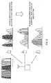
- the left side of Fig. 17 shows a frequency spectrum on a transmitting side and the right side shows a frequency spectrum on a terminal side.
- the frequency spectrum on the terminal side has a high level of reception at some places a low level of reception at others.
- the reception level of each subcarrier varies. If, in such a situation, a received signal is despread, orthogonality of multiplexed codes will be lost because amplitude levels of 16 subcarriers are different.
- the present invention has been developed in view of the above situation and an object thereof is to provide a wireless communication apparatus and a wireless communication method that can reduce interference of multiplexed signals.
- a wireless communication apparatus is a wireless communication apparatus performing a wireless communication by combining a multicarrier transmission system with a spread spectrum, and comprises: a rearrangement control part that ranks each subcarrier in accordance with a magnitude of received power based on received power information indicating received power of each subcarrier received from a communicating apparatus and groups subcarriers in descending or ascending order of the rank in accordance with a spreading factor; and a rearrangement part that distributes a spread code to each of the groups.
- a wireless communication apparatus is also a wireless communication apparatus performing a wireless communication by combining a multicarrier transmission system with a spread spectrum after determining an adaptive modulation parameter for each subcarrier based on propagation path information received from a communicating apparatus, and comprises: an adaptive modulation control part that groups subcarriers having the identical determined adaptive modulation parameter in accordance with a spreading factor; and a rearrangement part that distributes a transmission signal to each of the groups and also distributes a spread code to each of the groups.
- subcarriers having the same adaptive modulation parameter are grouped according to the spreading factor, a transmission signal is distributed to each group and also a spread code is distributed to each group, as described above, spread signals will have almost identical levels of amplitude. That is, in an adaptive modulation system, subcarriers having different received power levels are divided to some degree in equal intervals and thus, subcarriers having the same degree of modulation or the same rate of coding will have the same received power on the receiving side. Therefore, if despread on the receiving side, orthogonal relationships with multiplexed signals spread by other spread codes will almost be maintained. As a result, signals spread by other spread codes will not be interference components and thus, it becomes possible to prevent deterioration of signals and to realize high-quality communication.
- a wireless communication apparatus is also a wireless communication apparatus performing a wireless communication by combining a multicarrier transmission system with a spread spectrum after determining adaptive modulation parameters for a plurality of subcarrier groups consisting of a plurality of subcarriers based on propagation path information received from a communicating apparatus, and comprises: a rearrangement part that allocates a transmission signal to each of the subcarrier groups and also distributes a spread code to each of the subcarrier groups.
- subcarriers are grouped and spread as groups, as described above, processing can be made simpler than when a spread code is distributed to each subcarrier. Also, since transmission signals are distributed to each subcarrier group having the same adaptive modulation parameter and also spread codes are distributed to each subcarrier group, spread signals will have almost identical levels of amplitude. In an adaptive modulation system, a subcarrier group having the same degree of modulation or the same coding rate will have the same received power on the receiving side. Therefore, if despread on the receiving side, orthogonal relationships with multiplexed signals spread by other spread codes will almost be maintained. As a result, signals spread by other spread codes will not be interference components and thus, it becomes possible to prevent deterioration of signals and to realize high-quality communication.
- a wireless communication apparatus is also the wireless communication apparatus according to any of claims 1 to 3 performing a wireless communication by combining a multicarrier transmission system with a spread spectrum while spreading in both directions of a frequency axis and a time axis, and further comprises: a frequency spreading factor calculation part that calculates the number of subcarriers spreading in a frequency axis direction so that a product of a spreading factor in the frequency axis direction and that in a time axis direction be a constant value.
- the number of subcarriers spreading in the frequency axis direction is calculated so that the product of the spreading factor in the frequency axis and that in the time axis be a constant value, as described above, the number of subcarriers to be adjusted to an almost identical level can be made smaller. As a result, variations in amplitude will be smaller among subcarriers and orthogonality will be lost more rarely, enabling prevention of an increase in interference.
- a wireless communication apparatus is also a wireless communication apparatus performing a wireless communication by allocating a communication slot identified by one or more time channels defined by a fixed time length and one or more frequency channels defined by a fixed frequency band to each terminal device to be controlled, and comprises: a rearrangement control part that allocates subcarriers to each of the terminal devices; and a rearrangement part that distributes spread codes to the subcarriers allocated to each of the terminal devices.
- the rearrangement control part groups subcarriers having approximately identical received power according to the spreading factor based on received power information indicating received power of each subcarrier received from a communicating apparatus and allocates grouped subcarriers to each of the terminal devices.
- a wireless communication method is also a wireless communication method performing a wireless communication by combining a multicarrier transmission system with a spread spectrum, and comprises at least the steps of: receiving received power information indicating received power of each subcarrier from a communicating apparatus; ranking each subcarrier in accordance with a magnitude of received power based on the received received power information; grouping subcarriers in accordance with a spreading factor in descending or ascending order of the rank; and distributing a spread code to each of the groups.
- spread signals will have almost identical levels of amplitude and therefore, if despread on the receiving side, orthogonal relationships with multiplexed signals spread by other spread codes will almost be maintained. As a result, signals spread by other spread codes will not be interference components and thus, it becomes possible to prevent deterioration of signals and to realize high-quality communication.
- Fig. 1 is a block diagram showing an outline configuration of a transmitter according to a fist embodiment.
- a transmitter 1 data to be transmitted is added with an error correcting code by a coding part 2 and modulated by a modulation part 3.
- a multiplexing part (Mux part) 4 multiplexes the modulated data parallel-converted into as many portions as the number of subcarriers with a pilot signal used by the receiving side for estimating received SIR.
- an S/P conversion part 5 converts the data into parallel signals.
- each signal is copied by a copying part 6 to generate a plurality of signals.
- the number of copied signals is equal to a spreading factor. That is, if the spreading factor is 16, for example, a signal is copied to generate 16 signals.
- Each copied signal is multiplied in order by a spread code generated by a spread code generation part 7 in a multiplier 8.
- a rearrangement control part 9 controls each of signals spread after being grouped together with approximately identical levels of received power on a receiver side so that there is no great difference of reception levels on the receiver side.
- a transmission signal rearrangement part 10 rearranges a sequence of signals multiplied by spread codes. Then, Fourier transform processing is performed by an IFFT part 11 and guard intervals are inserted by a guard interval insertion part 12 to generate an OFDM signal.
- each subcarrier will be spread in order. That is, for SB1 (subcarrier 1) to SB16, the first data symbol is spread by spread codes 1 to 16, and for SB17 to SB32 the second data symbol is spread by the spread codes 1 to 16. Since an original data symbol is converted into 16-fold spread symbols by spread processing, as described above, though the transmission rate drops to 1/16, multiplexing can be performed using different spread codes for a spread spectrum and therefore, the transmission rate can still be maintained.
- Fig. 2 is a schematic diagram showing how subcarriers are rearranged in accordance with received power of the subcarriers.
- Fig. 2 is a schematic diagram and the total number of subcarriers is eleven and the number of subcarriers having approximately identical levels is three, but in an actual system, the total number of subcarriers is several hundreds and several dozens of subcarriers having approximately identical levels exist. In that case, spread codes can be distributed to subcarriers having approximately identical levels.
- Fig. 3 is a flow chart showing a rearrangement operation.
- power information by subcarrier is input based on received power information on the receiving side (step S1).
- subcarriers are numbered with reference to power (step S2).
- subcarriers are numbered in descending order of received power.
- the subcarrier of the subcarrier No. 38 has the highest received power
- the subcarrier of the subcarrier No. 12 has the third highest received power.
- subcarriers are blocked (grouped) based on the spreading factor (step S3).
- the first block consists of subcarriers having received power higher than the highest reference value and is made up of subcarriers having the first to sixteenth highest received power. As shown in Fig.
- subcarriers of the subcarrier Nos. 11, 12, 38, 39 and so on belong to this block.
- the second block consists of subcarriers having received power higher than the second highest reference value and is made up of subcarriers having the seventeenth to thirty-second highest received power. As shown in Fig. 3, for example, subcarriers of the subcarrier Nos. 35, 36, 100, 105 and so on belong to this block.
- one spread data symbol will be spread over to 16 subcarriers of each block (step S4) before being transmitted.
- spread signals will have approximately identical amplitude levels and therefore, if despread on the receiving side, orthogonal relationships with multiplexed signals spread by other spread codes will almost be maintained. As a result, signals spread by other spread codes will not be interference components and thus, deterioration of signals can be prevented.
- the transmitter side must be informed of the reception level of each subcarrier on the receiver side to rearrange amplitude levels
- various methods have been proposed for an adaptive modulation system and thus, the level on the receiving side can be known from the transmitter side by performing similar processing.
- the number of subcarriers in a group must be equal to the spreading factor or its integral multiple and therefore, though subcarriers are said to have approximately identical received power, a small amplitude difference may arise. In that case, it is also effective to match reception levels by making transmission output adjustments for each subcarrier through minor adjustments of power of transmitting subcarriers.
- the adaptive modulation/demodulation method is a system in which a plurality of degrees of modulation and coding rates is provided and adjusted to required CNRs (Carrier to noise ratio) needed by each for transmission.
- CNRs Carrier to noise ratio
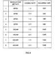
- Fig. 4 is a diagram showing relationships among modulation methods, coding rates, and required CNRs.
- Fig. 4 shows eight combinations of the coding/ modulation method.
- An adaptive modulation system provides a plurality of methods in which the required CNR is different from each other, as shown above, and an optimal modulation method is selected from the plurality of methods depending on reception conditions of each subcarrier.
- the above example is only an example and actually still more coding rates may be selected.
- the required CNR described above changes depending on an overall system and error correcting method and, though the example shown in Fig. 4 is only an example, each method is provided in such a way that the required CNRs are set at somewhat regular intervals.
- Fig. 5 is a diagram showing an example in which subcarriers are grouped based on the modulation method or coding rate. That is, in the second embodiment, as shown in Fig. 5, a group of the same modulation and coding methods will be a spread unit.
- Fig. 6 is a block diagram showing the outline configuration of a transmitter according to the second embodiment.
- a transmission signal rearrangement part 61 distributes signals corresponding to each modulation method and coding method depending on a signal input from an adaptive modulation control part 62. In the example shown in Fig. 4, signals are distributed among eight kinds. Each distributed signal obtains the same coding in each distributed group by each coding part 63. Then, each signal is multiplied by a spread code generated by a spread code generation part 64 in a multiplier 65 before being modulated by a subcarrier modulation part 66.
- a pilot signal is added/multiplexed by a multiplexing part (Mux part) 67 and parallel/serial conversion is performed by an S/P conversion part 68 before each signal is allocated to each subcarrier.
- a Fourier transform processing is performed by an IFFT part 69 and guard intervals are inserted by a guard interval insertion part 70 to generate an OFDM signal.
- circuits can be saved in an actual configuration by using the same circuit block for the same coding rate and the same modulation method.
- the second embodiment in a system in which subcarriers are separated into groups having the same degree of modulation or the same coding rate controlled by the adaptive modulation control part 62, as described above, groups thereof are utilized and spread processing is performed therein. Since, in an adaptive modulation system, levels of different received power of subcarriers are divided somewhat equidistantly, subcarriers selected based on the same level of degree of modulation and coding rate must have approximately the same power on the receiver side. Actually, however, the degree of modulation and the coding rate can take several values, as described above, and thus required power varies about between 1 and 2 dB, but grouping based on received power on the terminal side required for the first embodiment can be made unnecessary.
- modulated data will increase by the spreading factor.
- its number will decrease by a factor of the spreading factor.
- the spreading factor is 16
- the number of subcarriers of a subcarrier group that can use the same coding rate and the same modulation method controlled by an adaptive modulation/demodulation system is N
- control in an adaptive modulation/demodulation system is distinguished by the received CNR and the like and thus, if the groupings are unchanged, the number of subcarriers may not be a multiple of the spreading factor (16 in the previous example).
- the adaptive modulation/demodulation groupings and spread groups it is necessary to cause the adaptive modulation/demodulation groupings and spread groups to match. Two methods shown below can be considered.
- the first method is to rearrange a remainder after division to a group immediately below (a level with less required CNR). As a result, the number of carriers will be divisible by 16.
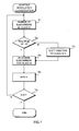
- Fig. 7 is a flow chart showing an operation to cause the adaptive modulation/demodulation groupings and spread groups to match.
- step T1 determine the number of subcarriers in class N (step T1) and determine whether the number is a multiple of 16 (step T2) . If the number is a multiple of 16, move to step T4 and, if not a multiple of 16, shift a fraction to class N-1 (step T3).
- the second method is to round off to the nearest multiple of 16.
- This flow chart is shown in Fig. 8.
- step R1 determine the number of subcarriers in class N (step R1) and determine whether the number is a multiple of 16 (step R2). If the number is a multiple of 16, move to step R4 and, if not a multiple of 16, round off the number (step R3). By rounding off the number, the number of subcarriers in class N-1 may increase or decrease.
- Fig. 9 is a diagram showing a concept of blocking of subcarriers in a third embodiment.
- the most fundamental method optimizes the modulation method and coding method for each subcarrier, but in an actual system, subcarriers may be blocked to some degree for adaptation to avoid complicated processing. Such a situation is shown in Fig. 9.
- processing similar to that in each of the above embodiments can be performed.
- the minimum unit is 16 when the spreading factor is 16 in the above example and thus, when subcarriers are made to have the same level of amplitude, many subcarriers may be dropped so that efficiency is degraded and, when adapted to the required CNR, substantial subcarrier power adjustments may be necessary, making realization in some cases impossible.
- adaptive modulation/demodulation it may in some cases be difficult to make the number of subcarriers in a group classified by the above adaptive modulation/demodulation an integral multiple of the spreading factor.
- Fig. 10 is a diagram how spreading occurs in two dimensions.
- Fig. 11 is a diagram showing the outline configuration of a transmitter that performs two-dimensional spreading.
- the basic method is the same as the adaptive modulation method shown in the second embodiment.
- the spreading factor is fixed to 16 (in a system of the spreading factor 16) and it is necessary to group subcarriers as a multiple of 16 on the frequency axis.
- a frequency spreading factor calculation part 110 to calculate the number of subcarriers spread along the frequency axis is provided prior to an adaptive modulation control part 62.
- Other components are the same as those of the transmitter according to the second embodiment shown in Fig. 6.
- Fig. 11 shows an example in which two-dimensional spreading is applied to adaptive modulation, but modulation itself may not be adaptive modulation.
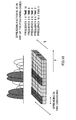
- FIG. 12 is a diagram showing the concept of OFDMA. Propagation characteristics between a base station and each terminal is different from terminal to terminal and thus, even if transmitted with the same transmission power, received power received by each terminal is different from subcarrier to subcarrier and received power is diverse. Since a subcarrier received with strong power has a lower error rate, overall characteristics can be improved, compared with a method in which subcarriers are allocated in order to each terminal, by allocating subcarriers whose reception at a terminal is strong to such a terminal for transmission.
- subcarriers distributed to each terminal according to OFDMA have constant received power at each terminal and therefore, allocation with only slight variations in amplitude is made possible by distributing subcarriers as a multiple of the spreading factor.
- Fig. 13 is a block diagram showing the outline configuration of a transmitter of OFDMA.
- a transmission signal rearrangement part 131 distributes signals corresponding to each modulation method, coding method, and each user (terminal device) depending on a signal input from an OFDMA control part 132.
- Each distributed signal is coded in a coding part 133 for each distributed user.
- each signal is multiplied by a spread code generated by a spread code generation part 134 in a multiplier 135 and spread before being modulated by a subcarrier modulation part 136.
- a pilot signal is added/multiplexed by a multiplexing part (Mux part) 137 and parallel/serial conversion is performed by an S/P conversion part 138 before each signal is allocated to each subcarrier.
- IFFT part 139 Fourier transform processing is performed by an IFFT part 139 and guard intervals are inserted by a guard interval insertion part 140 to generate an OFDM signal.
- the OFDMA control part 132 determines which subcarrier to allocate to each user. Distributed subcarriers whose amplitude level is better are aligned in a receiver of each user than when distributed randomly. In the fifth embodiment, spreading occurs in units of distributed users. As a result, spreading can occur within subcarriers without a difference of significant amplitude levels.
- each terminal gets subcarriers allocated in descending order of received power and all terminals get subcarriers with weak power and thus, it is never certain that subcarriers allocated to one reception terminal will have the same reception level.
- subcarriers having more aligned amplitudes can be put together by distributing in units of spread subcarriers (for example, 16) that will have an identical level at each terminal. Interference can thereby be reduced.
- Fig. 14 it is also effective to sub-channelize by bundling a certain number of subcarriers in OFDMA. That is, spreading occurs in units of one sub-channel block. Processing can thereby be simplified compared with when spreading occurs in units of subcarrier.
Landscapes
- Engineering & Computer Science (AREA)
- Signal Processing (AREA)
- Computer Networks & Wireless Communication (AREA)
- Quality & Reliability (AREA)
- Mobile Radio Communication Systems (AREA)
- Detection And Prevention Of Errors In Transmission (AREA)
Applications Claiming Priority (2)
| Application Number | Priority Date | Filing Date | Title |
|---|---|---|---|
| JP2005120427 | 2005-04-18 | ||
| PCT/JP2006/303559 WO2006114932A1 (ja) | 2005-04-18 | 2006-02-27 | 無線通信装置および無線通信方法 |
Publications (2)
| Publication Number | Publication Date |
|---|---|
| EP1876741A1 true EP1876741A1 (de) | 2008-01-09 |
| EP1876741A4 EP1876741A4 (de) | 2013-06-12 |
Family
ID=37214563
Family Applications (1)
| Application Number | Title | Priority Date | Filing Date |
|---|---|---|---|
| EP06714696.9A Withdrawn EP1876741A4 (de) | 2005-04-18 | 2006-02-27 | Vorrichtung und verfahren zur drahtlosen kommunikation |
Country Status (5)
| Country | Link |
|---|---|
| US (1) | US8094734B2 (de) |
| EP (1) | EP1876741A4 (de) |
| JP (1) | JPWO2006114932A1 (de) |
| CN (1) | CN101160762B (de) |
| WO (1) | WO2006114932A1 (de) |
Cited By (1)
| Publication number | Priority date | Publication date | Assignee | Title |
|---|---|---|---|---|
| US8654751B2 (en) | 2007-09-12 | 2014-02-18 | Sharp Kabushiki Kaisha | Radio communication method, radio communication system, and radio transmission apparatus |
Families Citing this family (6)
| Publication number | Priority date | Publication date | Assignee | Title |
|---|---|---|---|---|
| US8670493B2 (en) | 2005-06-22 | 2014-03-11 | Eices Research, Inc. | Systems and/or methods of increased privacy wireless communications |
| US8175068B2 (en) * | 2008-03-26 | 2012-05-08 | Advanced Receiver Technologies, Llc | Active spread code detection |
| KR101918026B1 (ko) | 2009-04-22 | 2018-11-13 | 삼성전자주식회사 | 무선통신 시스템에서 다중 주파수 할당을 지원하기 위한 방법 및 장치 |
| US10094210B2 (en) | 2013-10-01 | 2018-10-09 | Rocsol Technologies Inc. | Drilling system |
| CN113179669B (zh) * | 2018-12-05 | 2022-08-23 | 中兴通讯股份有限公司 | 用于使用离散频谱的技术 |
| US11863359B1 (en) * | 2021-05-11 | 2024-01-02 | Amazon Technologies, Inc. | Subcarrier pre-equalization technology for frequency selective fading characteristics of wireless channels |
Family Cites Families (22)
| Publication number | Priority date | Publication date | Assignee | Title |
|---|---|---|---|---|
| JP3236273B2 (ja) * | 1999-05-17 | 2001-12-10 | 三菱電機株式会社 | マルチキャリア伝送システムおよびマルチキャリア変調方法 |
| SG108240A1 (en) * | 2000-02-23 | 2005-01-28 | Ntt Docomo Inc | Multi-carrier cdma radio transmitting method and apparatus, and channel estimation method and apparatus for multi-carrier cdma radio transmitting system |
| JP2002190788A (ja) | 2000-03-17 | 2002-07-05 | Matsushita Electric Ind Co Ltd | 無線通信装置および無線通信方法 |
| US20020159425A1 (en) | 2000-03-17 | 2002-10-31 | Mitsuru Uesugi | Radio communication apparatus and radio communication method |
| EP1221778A4 (de) * | 2000-07-26 | 2008-08-27 | Mitsubishi Electric Corp | Vorrichtung zum senden, übertragen und empfangen von mehrträger cdma |
| JP3607643B2 (ja) * | 2001-07-13 | 2005-01-05 | 松下電器産業株式会社 | マルチキャリア送信装置、マルチキャリア受信装置、およびマルチキャリア無線通信方法 |
| JP2003046841A (ja) * | 2001-07-30 | 2003-02-14 | Fuji Photo Film Co Ltd | 簡易デジタルカメラ及びこれを用いた画像発注方法 |
| JP3628987B2 (ja) | 2001-07-31 | 2005-03-16 | 松下電器産業株式会社 | 無線通信装置および無線通信方法 |
| JP2003046481A (ja) | 2001-07-31 | 2003-02-14 | Matsushita Electric Ind Co Ltd | データ伝送装置およびデータ伝送方法 |
| JP3727283B2 (ja) | 2001-11-26 | 2005-12-14 | 松下電器産業株式会社 | 無線送信装置、無線受信装置及び無線送信方法 |
| JP2003304220A (ja) * | 2001-11-26 | 2003-10-24 | Matsushita Electric Ind Co Ltd | 無線送信装置及び無線送信方法 |
| JP3875086B2 (ja) * | 2001-11-30 | 2007-01-31 | ソフトバンクテレコム株式会社 | 直交周波数分割多重システムおよび送受信装置 |
| JP4334274B2 (ja) | 2002-05-16 | 2009-09-30 | 株式会社エヌ・ティ・ティ・ドコモ | マルチキャリア伝送用送信機及びマルチキャリア伝送方法 |
| CA2428576C (en) | 2002-05-16 | 2008-10-07 | Ntt Docomo, Inc. | Transmitter for multi-carrier transmission and multi-carrier transmitting method |
| JP3921419B2 (ja) * | 2002-06-28 | 2007-05-30 | 松下電器産業株式会社 | Ofdm−cdma通信装置及びofdm−cdma通信方法 |
| JP4041719B2 (ja) | 2002-10-09 | 2008-01-30 | 株式会社エヌ・ティ・ティ・ドコモ | 無線通信システム、無線通信方法、これらに用いて好適な送信装置及び受信装置 |
| JP4038114B2 (ja) * | 2002-10-29 | 2008-01-23 | 松下電器産業株式会社 | 無線送信装置及び無線送信方法 |
| US7317750B2 (en) * | 2002-10-31 | 2008-01-08 | Lot 41 Acquisition Foundation, Llc | Orthogonal superposition coding for direct-sequence communications |
| US7302238B2 (en) * | 2003-04-25 | 2007-11-27 | Samsung Electronics Co., Ltd. | Transmit diversity system, method and computer program product |
| US7123580B2 (en) * | 2004-01-16 | 2006-10-17 | Nokia Corporation | Multiple user adaptive modulation scheme for MC-CDMA |
| JP4012167B2 (ja) * | 2004-03-31 | 2007-11-21 | 株式会社東芝 | 無線通信システム |
| JP2005318434A (ja) | 2004-04-30 | 2005-11-10 | Matsushita Electric Ind Co Ltd | 送信装置及びスケジューリング方法 |
-
2006
- 2006-02-27 JP JP2007514479A patent/JPWO2006114932A1/ja not_active Withdrawn
- 2006-02-27 US US11/911,309 patent/US8094734B2/en not_active Expired - Fee Related
- 2006-02-27 CN CN2006800124690A patent/CN101160762B/zh not_active Expired - Fee Related
- 2006-02-27 WO PCT/JP2006/303559 patent/WO2006114932A1/ja not_active Ceased
- 2006-02-27 EP EP06714696.9A patent/EP1876741A4/de not_active Withdrawn
Cited By (2)
| Publication number | Priority date | Publication date | Assignee | Title |
|---|---|---|---|---|
| US8654751B2 (en) | 2007-09-12 | 2014-02-18 | Sharp Kabushiki Kaisha | Radio communication method, radio communication system, and radio transmission apparatus |
| US8681688B2 (en) | 2007-09-12 | 2014-03-25 | Sharp Kabushiki Kaisha | Radio communication method, radio communication system, and radio transmission apparatus |
Also Published As
| Publication number | Publication date |
|---|---|
| CN101160762B (zh) | 2011-04-20 |
| US8094734B2 (en) | 2012-01-10 |
| EP1876741A4 (de) | 2013-06-12 |
| JPWO2006114932A1 (ja) | 2008-12-11 |
| WO2006114932A1 (ja) | 2006-11-02 |
| US20090016412A1 (en) | 2009-01-15 |
| CN101160762A (zh) | 2008-04-09 |
Similar Documents
| Publication | Publication Date | Title |
|---|---|---|
| KR100640461B1 (ko) | 직교 주파수 분할 다중 접속 방식을 사용하는 이동 통신시스템에서 서브 채널 할당 장치 및 방법 | |
| KR101017259B1 (ko) | 송신장치, 수신장치, 이동통신 시스템, 및 송신제어방법 | |
| KR100918730B1 (ko) | 직교 주파수 분할 다중 방식을 사용하는 통신 시스템에서기지국 구분을 위한 파일럿 패턴 세트 송수신 장치 및 방법 | |
| US8130711B2 (en) | Method for allocating pilots | |
| US8422478B2 (en) | Radio transmission device | |
| KR100640474B1 (ko) | 다중 반송파 기반의 코드분할다중접속 시스템을 위한 하향링크 자원 할당 방법 | |
| US20050226141A1 (en) | Apparatus and method for transmitting/receiving pilot code pattern for identification of base station in communication system using orthogonal frequency division multiplexing scheme | |
| US8588342B2 (en) | Mobile terminal for performing a communication by using sub carriers | |
| KR100929100B1 (ko) | 직교 주파수 분할 다중 접속 방식을 사용하는 통신 시스템에서 서브 채널 할당 장치 및 방법 | |
| AU2005234350A1 (en) | Apparatus and method for controlling transmission power in communication systems using orthogonal frequency division multiple access scheme | |
| US8094734B2 (en) | Wireless communication apparatus and wireless communication method | |
| KR20060092400A (ko) | Mimo-ofdma 통신 시스템에서 채널 상태 정보 궤환 및 이를 이용한 자원 할당 시스템 및 방법 | |
| KR101339507B1 (ko) | 부호어의 전송방법 | |
| US20090034456A1 (en) | Communications Systems | |
| US7428248B2 (en) | Code allocation method in an MC-CDMA telecommunication system | |
| JP2006054745A (ja) | 無線通信装置 | |
| EP1359678B1 (de) | Kodeverteilverfahren in einem Mehrträger-CDMA Nachrichtenübertragungssystem | |
| JP3962008B2 (ja) | 無線通信システム及び無線通信装置ならびに無線通信方法 | |
| RU2414072C2 (ru) | Передающее устройство, приемное устройство, система мобильной связи и способ управления передачей |
Legal Events
| Date | Code | Title | Description |
|---|---|---|---|
| PUAI | Public reference made under article 153(3) epc to a published international application that has entered the european phase |
Free format text: ORIGINAL CODE: 0009012 |
|
| 17P | Request for examination filed |
Effective date: 20071114 |
|
| AK | Designated contracting states |
Kind code of ref document: A1 Designated state(s): AT BE BG CH CY CZ DE DK EE ES FI FR GB GR HU IE IS IT LI LT LU LV MC NL PL PT RO SE SI SK TR |
|
| DAX | Request for extension of the european patent (deleted) | ||
| A4 | Supplementary search report drawn up and despatched |
Effective date: 20130514 |
|
| RIC1 | Information provided on ipc code assigned before grant |
Ipc: H04L 27/26 20060101ALI20130503BHEP Ipc: H04J 13/10 20110101ALI20130503BHEP Ipc: H04L 5/00 20060101AFI20130503BHEP |
|
| STAA | Information on the status of an ep patent application or granted ep patent |
Free format text: STATUS: THE APPLICATION HAS BEEN WITHDRAWN |
|
| 18W | Application withdrawn |
Effective date: 20130723 |