EP1876815A2 - Procédé de traitement d'images pour système de saisie de pointage - Google Patents
Procédé de traitement d'images pour système de saisie de pointage Download PDFInfo
- Publication number
- EP1876815A2 EP1876815A2 EP07011407A EP07011407A EP1876815A2 EP 1876815 A2 EP1876815 A2 EP 1876815A2 EP 07011407 A EP07011407 A EP 07011407A EP 07011407 A EP07011407 A EP 07011407A EP 1876815 A2 EP1876815 A2 EP 1876815A2
- Authority
- EP
- European Patent Office
- Prior art keywords
- image
- display screen
- aligning
- color channel
- pickup device
- Prior art date
- Legal status (The legal status is an assumption and is not a legal conclusion. Google has not performed a legal analysis and makes no representation as to the accuracy of the status listed.)
- Withdrawn
Links
Images







Classifications
-
- G—PHYSICS
- G06—COMPUTING OR CALCULATING; COUNTING
- G06F—ELECTRIC DIGITAL DATA PROCESSING
- G06F3/00—Input arrangements for transferring data to be processed into a form capable of being handled by the computer; Output arrangements for transferring data from processing unit to output unit, e.g. interface arrangements
- G06F3/01—Input arrangements or combined input and output arrangements for interaction between user and computer
- G06F3/03—Arrangements for converting the position or the displacement of a member into a coded form
- G06F3/041—Digitisers, e.g. for touch screens or touch pads, characterised by the transducing means
- G06F3/0416—Control or interface arrangements specially adapted for digitisers
- G06F3/0418—Control or interface arrangements specially adapted for digitisers for error correction or compensation, e.g. based on parallax, calibration or alignment
-
- G—PHYSICS
- G06—COMPUTING OR CALCULATING; COUNTING
- G06F—ELECTRIC DIGITAL DATA PROCESSING
- G06F3/00—Input arrangements for transferring data to be processed into a form capable of being handled by the computer; Output arrangements for transferring data from processing unit to output unit, e.g. interface arrangements
- G06F3/01—Input arrangements or combined input and output arrangements for interaction between user and computer
- G06F3/03—Arrangements for converting the position or the displacement of a member into a coded form
- G06F3/033—Pointing devices displaced or positioned by the user, e.g. mice, trackballs, pens or joysticks; Accessories therefor
- G06F3/038—Control and interface arrangements therefor, e.g. drivers or device-embedded control circuitry
- G06F3/0386—Control and interface arrangements therefor, e.g. drivers or device-embedded control circuitry for light pen
-
- G—PHYSICS
- G06—COMPUTING OR CALCULATING; COUNTING
- G06F—ELECTRIC DIGITAL DATA PROCESSING
- G06F3/00—Input arrangements for transferring data to be processed into a form capable of being handled by the computer; Output arrangements for transferring data from processing unit to output unit, e.g. interface arrangements
- G06F3/01—Input arrangements or combined input and output arrangements for interaction between user and computer
- G06F3/03—Arrangements for converting the position or the displacement of a member into a coded form
- G06F3/041—Digitisers, e.g. for touch screens or touch pads, characterised by the transducing means
- G06F3/042—Digitisers, e.g. for touch screens or touch pads, characterised by the transducing means by opto-electronic means
- G06F3/0425—Digitisers, e.g. for touch screens or touch pads, characterised by the transducing means by opto-electronic means using a single imaging device like a video camera for tracking the absolute position of a single or a plurality of objects with respect to an imaged reference surface, e.g. video camera imaging a display or a projection screen, a table or a wall surface, on which a computer generated image is displayed or projected
Definitions
- the present invention relates to an image processing method, and more particularly to an image processing method of a pointer input system.
- the image processing method of the pointer input system mainly includes a calibrating method and a tracking method.
- a calibrating method For performing the calibrating method, a aligning pattern is inputted onto the display screen, and the image of the display screen including the aligning pattern is then captured by the image pickup device to obtain a aligning data. After the aligning data is compared with a predetermined reference data, a space conversion relationship between the display screen and the image pickup device is obtained.
- the image of the display screen including the light spot is captured by the image pickup device to obtain an output data relevant to the light-spot position according to the space conversion relationship.
- the output data is processed by a data processing device, related output pointer is projected onto the display screen through an image projecting system.
- a full-color image contains a variety of colors including for example a red color, a blue color and a green color. Since the full-color image is usually processed according to an arithmetic average or a weighted average of a red color value, a blue color value and a green color value, the characteristic properties of having different signal-to-noise ratios (S/N) and gains in each or composite color channel are not utilized to enhance the image processing capability. Under this circumstance, since the data amount of processing the full-color image is very huge, the image processing efficiency and the data transmitting speed fail to be increased and the stability of the pointer input system is impaired.
- S/N signal-to-noise ratios
- Another object of the present invention provides an image processing method of a pointer input system for use with a cathode ray tube (CRT) monitor, a liquid crystal display (LCD) screen, a plasma display panel or a projection screen.
- CTR cathode ray tube
- LCD liquid crystal display
- a calibrating method of a pointer input system includes steps of displaying a aligning test pattern on a display screen, capturing the display screen by an image pickup device to obtain a aligning image including the aligning test pattern, generating a color channel image according to the aligning image, scanning a region of interest of the color channel image to obtain a aligning data, and comparing the aligning data with a predetermined reference data to obtain a space conversion relationship between the display screen and the image pickup device.
- a tracking method of a pointer input system includes steps of allowing a pointer generating device to issue a light spot on a display screen, capturing the display screen by an image pickup device to obtain a tracking image including the light spot, generating a color channel image according to the tracking image, eliminating background noise of the color channel image, scanning a region of interest of the color channel image to obtain a scan data, generating an output data associated with the position of the light spot according to a space conversion relationship and the scan data, and displaying a pointer corresponding to the light spot on the display screen through an image projecting system according to the output data.
- the image processing capability of the pointer input system is enhanced. Instead of using the full-color image, a color channel image is processed. Since the data amount of processing the color channel image is largely reduced, the image processing efficiency and the data transmitting speed are both enhanced.
- Fig. 1 schematically illustrates three typical aligning test patterns used in an image processing method of a pointer input system according to the present invention
- Fig. 2 is a flowchart illustrating a calibrating method of a pointer input system according to a first embodiment of the present invention
- Fig. 3 is a schematic view of the pointer input system for implementing the calibrating method of Fig. 2;
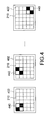
- Fig. 4 schematically illustrates segmental patterns divided by a aligning test pattern to be successively projected onto the display screen
- Fig. 5 schematically illustrates that light spots issued from a pointer generating device are projected onto specified locations of the display screen
- Fig. 6 schematically illustrates that a aligning test pattern is arranged at a corner of the display screen
- Fig. 7 is a flowchart illustrating a calibrating method of a pointer input system according to a second embodiment of the present invention.
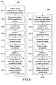
- Fig. 8 is a flowchart illustrating a calibrating method of a pointer input system according to a third embodiment of the present invention.
- Fig. 9 schematically illustrates a aligning test pattern for used in a pre-calibrating method
- Fig. 10 schematically illustrates a aligning test pattern for used in a full-screen calibrating method
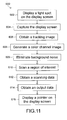
- Fig. 11 is a flowchart illustrating a tracking method of a pointer input system according to an embodiment of the present invention.
- Fig. 12 is a schematic view of the pointer input system for implementing the tracking method of Fig. 11;
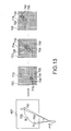
- Fig. 13 is a flowchart illustrating a tracking method of a pointer input system according to another embodiment of the present invention.
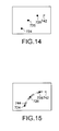
- Fig. 14 is a schematic view illustrating an anticipated extrapolation position constructed from known central positions of the elongated zones by extrapolation algorithm
- Fig. 15 is a schematic view illustrating an interpolation position constructed from known central positions of the elongated zones and the extrapolation position by interpolation algorithm.
- Fig. 16 is a schematic view illustrating some sensing points for discriminating change of the surrounding's light.
- the present invention provides an image processing method of a pointer input system by referring to a color channel image of an image pickup device in order to increase the image processing capability, the image processing efficiency and the data transmitting speed of the pointer input system.
- the image processing method of the present invention includes a calibrating method and a tracking processing. By adjusting the resolution of the image pickup device, the image obtained during the calibrating method and the image obtained during the tracking method have different resolutions. For example, the resolution of the image obtained during the tracking method is smaller than that obtained during the calibrating method. As a consequence, the aligning accuracy and the tracking processing efficiency and transmitting speed are enhanced.
- the aligning test patterns of Fig. 1 include a checkerboard pattern 210, a block dot pattern 220 and a cross dot pattern 230, respectively.
- the aligning test patterns may have arbitrary patterns.
- the checkerboard pattern 210 is used for illustration.
- Fig. 2 is a flowchart 300 illustrating a calibrating method of a pointer input system according to a first embodiment of the present invention.
- Fig. 3 is a schematic view of the pointer input system for implementing the calibrating method of Fig. 2.
- the pointer input system of Fig. 3 principally includes a display screen 402, an image projecting system 404 and an image pickup device 408.
- a aligning test pattern (e.g. the checkerboard pattern 210) is displayed on the display screen 402 through the image projecting system 404 (e.g. a projector).
- the checkerboard pattern 210 is divided into multiple segmental patterns 440, e.g. 2x2 segmental patterns. These segmental patterns 440 are successively projected onto the display screen 402. Alternatively, as shown in Fig. 5, several light spots 422 issued from a pointer generating device 418 are projected onto specified locations 420 of the display screen 402. Alternatively, as shown in Fig. 6, the checkerboard pattern 210 may be arranged at different sites of the display screen 402.
- the checkerboard pattern 210 may be arranged at a middle site, a corner or any arbitrary site of the display screen 402. After the calibrating method has been performed on different corners of the display screen 402, the interference from background noise is reduced.
- An example of the display screen 402 includes but is not limited to a cathode ray tube (CRT) monitor, a liquid crystal display (LCD) screen, a plasma display panel or a projection screen.
- Step 304 by adjusting the parameters including positions, exposure time, gamma values, gain values or brightness values of the image pickup device 408 (e.g. an array-type photosensing device), the numbers of recognized relevant marks 412 within a preview window 410 are varied and recorded.
- the image having the highest number of recognized marks 412 is obtained, a capture field 401 and an optimal parameter of the image pickup device 408 are determined accordingly.
- the locations of the marks 412 correspond to intersection points 413 of every four adjacent squares of the checkerboard pattern 210.
- the image pickup device 408 may be fastened onto the display screen 402 or fixed in the vicinity of the image projecting system 404, so that the positional parameter of the image pickup device 408 is kept unchanged.
- Step 306 After the display screen 402 is captured by the image pickup device 408 (Step 306), a aligning image 405 including the aligning test pattern is obtained (Step 308).
- a color channel image is generated (Step 310).
- the color channel image is a single color channel image or a composite color channel image included in the aligning image 405.
- the color channel image is a red channel image or a composite red-and-blue channel image included in the aligning image 405.
- a polarizer 406 and an optical filter 407 are disposed in front of the image pickup device 408 for filtering off the background noise from the image projecting system 404 or the surrounding light sources.
- a region of interest 409 of the color channel image is scanned.
- the region of interest 409 corresponds to the input field 403 of the image projecting system 404. Since the image of the aligning test pattern or the input light spot is greater than one pixel, the region of interest 409 may be canned in alternate rows or in alternate columns so as to enhance the data transmitting speed and the processing speed. Moreover, since only the region of interest 409 is scanned, the interference from outside area of the region of interest 409 is minimized and the aligning accuracy is increased.
- a aligning data is obtained (Step 314).
- the aligning data is compared with a predetermined reference data with respect to the three dimensional coordinate system and the relative locations (Step 315).
- the reference data includes many spatial coordinate values of the checkerboard pattern 210.
- a space conversion relationship between the display screen 402 and the image pickup device 408 is calculated (Step 316). Meanwhile, the calibrating method of the image processing method of the pointer input system is implemented.
- a second embodiment of a calibrating method of the image processing method according to the present invention will be illustrated with reference to a flowchart 350 of Fig. 7.
- the steps 302, 304, 306, 308, 310, 312, 314, 315 and 316 are identical to those described in the flowchart 300 of Fig. 2, and are not redundantly described herein.
- a discriminating procedure 340 is included in the calibrating method of the present invention after Step 316. If a difference between the coordinate value of the aligning data converted by the space conversion relationship (e.g.
- Step 342 the accuracy of the space conversion relationship is acceptable and the calibrating method is terminated. Otherwise, some important parameters of the pointer input system (e.g. the number of pixels per frame of the image projecting system 404 or the aspect ratio of the image projecting system 404) are automatically detected. If these parameters of the pointer input system are correct (Step 344), the above steps 302 ⁇ 316 are repeated to obtain a new space conversion relationship. Otherwise, after the parameters are modified (Step 346), the above steps 302 ⁇ 316 are repeated.
- a threshold value e.g. the number of pixels per frame of the image projecting system 404 or the aspect ratio of the image projecting system 404
- a third embodiment of a calibrating method of the image processing method according to the present invention will be illustrated with reference to a flowchart 500 of Fig. 8.
- This calibrating method of Fig. 8 includes a pre-calibrating method 520 and a full-screen calibrating method 530.
- Fig. 9 and Fig. 10 schematically illustrate two aligning test patterns used in the pre-calibrating method 520 and the full-screen calibrating method 530, respectively.
- the calibrating method according to the third embodiment of the present invention will be illustrated with reference to Figs. 8, 9 and 10.
- a first aligning test pattern e.g. a relatively smaller checkerboard pattern 450
- the image projecting system 404 e.g.
- Step 506 a projector
- Step 508 a second aligning test pattern (e.g. a relatively larger checkerboard pattern 460) is projected onto the display screen 402 through the image projecting system 404.
- Step 512 the steps 306, 308, 310, 312, 314 and 315 are carried out again to obtain a second space conversion relationship between the display screen 402 and the image pickup device 408 is calculated.
- the full-screen calibrating method 530 is implemented. For enhancing convenience, it is preferred that the full-screen calibrating method 530 is automatically performed.
- the discriminating procedure 340 as described in Fig. 7 is done after the pre-calibrating method 520 or the full-screen calibrating method 530, thereby discriminating whether the accuracy of the first space conversion relationship or the second space conversion relationship is acceptable.
- Fig. 11 is a flowchart 600 illustrating a tracking method of the image processing method of the pointer input system according to the present invention.
- Fig. 12 is a schematic view of the pointer input system for implementing the tracking method. Please refer Fig. 11 and 12.
- a light spot 702 issued from a pointer generating device 418 is projected onto the display screen 402.
- a tracking image 704 is generated (Step 606).
- the tracking image 704 is composed of multiple pixels 703.
- the image pickup device 408 is for example an array-type photosensing device.
- the image of the light spot 702 on the tracking image 704 is substantially an elongated zone 706.
- a color channel image is obtained (Step 608).
- the color channel image is a single color channel image or a composite color channel image included in the tracking image 704.
- the color channel image is a red channel image or a composite red-and-blue channel image included in the tracking image 704. Since the background noise resulting from the image projecting system 404 or the surrounding light sources may interfere with the color channel image, the background noise is eliminated (Step 609).
- a polarizer 406 and an optical filter 407 are disposed in front of the image pickup device 408 for filtering off the background noise.
- Step 610 a region of interest 705 of the color channel image is scanned.
- the region of interest 705 corresponds to the input field 403 of the image projecting system 404. Since the size of the elongated zone 706 is more than one pixel 703, the region of interest 705 may be canned in alternate rows or in alternate columns so as to enhance the data transmitting speed and the processing speed. Moreover, since only the region of interest 705 is scanned, the interference from outside area of the region of interest 705 is minimized and the tracking accuracy is increased.
- a scan data is obtained (Step 612).
- an output data associated with the position of the light spot 702 is generated (Step 614).
- specified optical attributes e.g. the gray scales or 8-bit brightness values
- the characteristic values of respective pixels 703 are substantially weight coefficients.
- a central position 708 of the elongated zone 706 is obtained by calculating the weighted average of the 8-bit brightness values of all pixels 703 included in the elongated zone 706. That is, the central position 708 is at the center of mass of the elongated zone 706.
- the central position 708 of the elongated zone 706 is situated at the pixel having the maximum optical attribute or the pixel having the critical optical attribute.
- the optical attribute includes but is not limited to brightness, color, size or shape.
- the output data is generated after the central position 708 of the elongated zone 706 is subject to a space conversion according to the space conversion relationship.
- the pixels are denoted as either bright spot or non-bright spot by evaluating 2-bit brightness values of the pixels.
- the weighted average of the 8-bit brightness values of all pixels 703 included in the elongated zone 706 is much more precise for searching the light-spot position.
- Step 614 a pointer 710 corresponding to the light spot 702 is displayed on the display screen 402 through the image projecting system 404 (Step 616).
- Fig. 13 is a schematic view of the pointer input system for implementing the tracking method according to another embodiment of the present invention.
- the light spot 702 issued from the pointer generating device 418 is projected onto a point A the display screen 402 and moved to the point C through the point B.
- the display screen 402 including the light spot 702 are continuously captured by the image pickup device 408, thereby successively generating tracking images 712, 714 and 716.
- the central positions 724, 726 and 728 of the elongated zones 718, 720 and 722 of the tracking images 712, 714 and 716 are calculated and recorded.
- continuous moving actions and relative positions of the continuously captured light spots 702 are monitored and tracked.
- the central positions 724, 726 and 728 are subject to space conversions according to the space conversion relationship, corresponding output data are generated and displayed on the display screen 402 through the image projecting system 404.
- the central positions 724, 726 and 728 of the elongated zones 718, 720 and 722 are obtained at the center of mass, the pixel having the maximum optical attribute or the pixel having the critical optical attribute.
- the optical attribute includes but is not limited to brightness, color, size or shape.
- respective terminal portions 730, 732 and 734 of the elongated zones 718, 720 and 722 are defined.
- one third of the elongated zone 718, 720 or 722 at the rear along the moving direction may be defined as the terminal portions 730, 732 or 734.
- the central positions 736, 738 and 740 of the terminal portions 730, 732 and 734 are obtained, respectively.
- the track corresponding to the moving spot 702 are generated and displayed on the display screen 402 through the image projecting system 404. As a consequence, a time delay resulting from data processing and transmission is reduced and the inconsistence between the input data and the output data will be minimized.
- the central positions 724, 726 and 728 of the elongated zones 718, 720 and 722 are recognized.
- extrapolation algorithm at least an extrapolation position 742 beyond the set of known positions 724, 726 and 728 will be anticipated. Consequently, the problem of causing time delay is reduced.
- interpolation position 744 is obtained from the known central positions 724, 726 and 728 and the extrapolation position 742 by interpolation algorithm (e.g. linear or bilinear interpolation algorithm). As the number of the interpolation position 744 is increase, the movement of the pointer looks smoother.
- interpolation algorithm e.g. linear or bilinear interpolation algorithm
- At least an extrapolation position beyond the set of known central positions 736, 738 and 740 of the terminal portions 730, 732 and 734 may be anticipated by extrapolation algorithm.
- several interpolation positions may be obtained from the known central positions 736, 738 and 740 and the extrapolation position 742 by interpolation algorithm, so that the movement of the pointer looks much smoother.
- multiple pointer generating devices 418 are employed to project a plurality of light spots 702 onto the display screen 402, so that the purpose of implementing multi-input or opinion exchange will be achieved.
- Fig. 16 schematically illustrating a method of detecting change of the surrounding's light by using the pointer input system of the present invention.
- several sensing points 750, 752, 754 and 756 are disposed within the capture field 401 for the image pickup device 408. If the change of the surrounding's light is over a predetermined signal level, it is meant that the background noise is increased. Under this circumstance, the gain values may be automatically adjusted and thus the influence of the light emitted from the image projecting system 404 is minimized.
- the predetermined signal levels of the sensing points 750, 752, 754 and 756 are different. Moreover, the number, size and location of the sensing points 750, 752, 754 and 756 may be varied as required.
Landscapes
- Engineering & Computer Science (AREA)
- General Engineering & Computer Science (AREA)
- Theoretical Computer Science (AREA)
- Human Computer Interaction (AREA)
- Physics & Mathematics (AREA)
- General Physics & Mathematics (AREA)
- Multimedia (AREA)
- Image Processing (AREA)
- Facsimile Image Signal Circuits (AREA)
- Controls And Circuits For Display Device (AREA)
Applications Claiming Priority (1)
| Application Number | Priority Date | Filing Date | Title |
|---|---|---|---|
| CN2006101005366A CN101102391B (zh) | 2006-07-03 | 2006-07-03 | 指针输入系统的影像处理的校准及追迹方法 |
Publications (2)
| Publication Number | Publication Date |
|---|---|
| EP1876815A2 true EP1876815A2 (fr) | 2008-01-09 |
| EP1876815A3 EP1876815A3 (fr) | 2008-03-12 |
Family
ID=38630320
Family Applications (1)
| Application Number | Title | Priority Date | Filing Date |
|---|---|---|---|
| EP07011407A Withdrawn EP1876815A3 (fr) | 2006-07-03 | 2007-06-11 | Procédé de traitement d'images pour système de saisie de pointage |
Country Status (2)
| Country | Link |
|---|---|
| EP (1) | EP1876815A3 (fr) |
| CN (1) | CN101102391B (fr) |
Families Citing this family (3)
| Publication number | Priority date | Publication date | Assignee | Title |
|---|---|---|---|---|
| JP2010015535A (ja) * | 2008-06-02 | 2010-01-21 | Sony Corp | 入力装置、制御システム、ハンドヘルド装置及び校正方法 |
| CN111462247B (zh) * | 2020-03-13 | 2024-04-02 | 中天智领(北京)科技有限公司 | 一种用于屏幕交互的光标位置校准方法及装置 |
| CN113259644B (zh) * | 2021-05-17 | 2022-07-22 | 青岛海信激光显示股份有限公司 | 激光投影系统及图像校正方法 |
Family Cites Families (10)
| Publication number | Priority date | Publication date | Assignee | Title |
|---|---|---|---|---|
| US6050690A (en) * | 1998-01-08 | 2000-04-18 | Siemens Information And Communication Networks, Inc. | Apparatus and method for focusing a projected image |
| EP1133752A1 (fr) * | 1998-10-21 | 2001-09-19 | VLG Virtual Laser Systems GmbH | Dispositif d'entree d'un ordinateur |
| JP4176230B2 (ja) * | 1999-03-19 | 2008-11-05 | 株式会社ルネサステクノロジ | 座標位置制御システム、座標位置制御方法およびその方法をコンピュータに実行させるプログラムを記録したコンピュータ読み取り可能な記録媒体 |
| JP3842515B2 (ja) * | 2000-03-24 | 2006-11-08 | セイコーエプソン株式会社 | 多重解像度画像解析による指示位置検出 |
| US6729731B2 (en) * | 2001-06-11 | 2004-05-04 | Info Valley Corporation | Untethered laser pointer for use with computer display |
| DE10347388A1 (de) * | 2003-10-08 | 2005-05-04 | Zeiss Carl Jena Gmbh | Anordnung zur Korrektur der visuellen Darstellung von Bildinformationen |
| US7125122B2 (en) * | 2004-02-02 | 2006-10-24 | Sharp Laboratories Of America, Inc. | Projection system with corrective image transformation |
| JP3882929B2 (ja) * | 2004-03-29 | 2007-02-21 | セイコーエプソン株式会社 | 画像処理システム、プロジェクタおよび画像処理方法 |
| US7137707B2 (en) * | 2004-07-01 | 2006-11-21 | Mitsubishi Electric Research Laboratories, Inc | Projector-camera system with laser pointers |
| CN1320810C (zh) * | 2005-03-21 | 2007-06-06 | 四川华控图形科技有限公司 | 用于多通道投影显示系统的色彩校正方法 |
-
2006
- 2006-07-03 CN CN2006101005366A patent/CN101102391B/zh not_active Expired - Fee Related
-
2007
- 2007-06-11 EP EP07011407A patent/EP1876815A3/fr not_active Withdrawn
Also Published As
| Publication number | Publication date |
|---|---|
| CN101102391A (zh) | 2008-01-09 |
| EP1876815A3 (fr) | 2008-03-12 |
| CN101102391B (zh) | 2010-10-27 |
Similar Documents
| Publication | Publication Date | Title |
|---|---|---|
| US7852316B2 (en) | Image processing method of pointer input system | |
| US8259063B2 (en) | Input method of pointer input system | |
| US6198514B1 (en) | Color misconvergence measurement using a common monochrome image | |
| EP1876517A1 (fr) | Procédé de saisie pour système de saisie de pointage | |
| KR100591731B1 (ko) | 화상 처리 시스템, 프로젝터, 정보 기억 매체 및 화상처리 방법 | |
| US9135851B2 (en) | Methods and systems for measuring and correcting electronic visual displays | |
| KR100215177B1 (ko) | 영상 데이터 보간 장치 | |
| EP1638345A1 (fr) | Procede de calcul de donnees de correction de caracteristiques d'affichage, programme de calcul de donnees de correction de caracteristiques d'affichage et dispositif de calcul de donnees de correction de caracteristiques d'affichage | |
| US7227592B2 (en) | Self-correcting rear projection television | |
| US9322707B2 (en) | Method for measuring luminance of light-emitting display panel | |
| WO1999053693A1 (fr) | Systeme multivision, procede d'etalonnage de couleurs et visualisation | |
| KR102138778B1 (ko) | 테스트 차트 및 그 사용 방법 | |
| JPH0658594B2 (ja) | 表示特性確認方法 | |
| EP1876815A2 (fr) | Procédé de traitement d'images pour système de saisie de pointage | |
| JP3618713B2 (ja) | ディスプレイ画面検査方法およびディスプレイ画面検査装置 | |
| JP2002100291A (ja) | カラーブラウン管の電子ビーム強度分布測定方法およびその装置並びにカラーブラウン管の製造方法 | |
| US5267038A (en) | Synthetic aperture video photometer system | |
| JP2634401B2 (ja) | カラーテレビ受像機のコンバーゼンス測定装置 | |
| JP2005031493A (ja) | 平面型表示装置および平面型表示装置の調整方法 | |
| US20070291121A1 (en) | Computer executable image quality detection system | |
| US5536192A (en) | Method for measuring convergence of a color cathode ray tube and apparatus thereof | |
| KR20010034160A (ko) | 전자 빔 프로파일 측정 방법 및 시스템 | |
| US7456908B2 (en) | Method of performing convergence calibration for a display | |
| USRE38574E1 (en) | Method and apparatus for reducing visibility of damping wires in aperture grill display tubes | |
| JP3495570B2 (ja) | 階調特性測定装置 |
Legal Events
| Date | Code | Title | Description |
|---|---|---|---|
| PUAI | Public reference made under article 153(3) epc to a published international application that has entered the european phase |
Free format text: ORIGINAL CODE: 0009012 |
|
| AK | Designated contracting states |
Kind code of ref document: A2 Designated state(s): AT BE BG CH CY CZ DE DK EE ES FI FR GB GR HU IE IS IT LI LT LU LV MC MT NL PL PT RO SE SI SK TR |
|
| AX | Request for extension of the european patent |
Extension state: AL BA HR MK YU |
|
| PUAL | Search report despatched |
Free format text: ORIGINAL CODE: 0009013 |
|
| AK | Designated contracting states |
Kind code of ref document: A3 Designated state(s): AT BE BG CH CY CZ DE DK EE ES FI FR GB GR HU IE IS IT LI LT LU LV MC MT NL PL PT RO SE SI SK TR |
|
| AX | Request for extension of the european patent |
Extension state: AL BA HR MK YU |
|
| 17P | Request for examination filed |
Effective date: 20080909 |
|
| 17Q | First examination report despatched |
Effective date: 20081009 |
|
| AKX | Designation fees paid |
Designated state(s): AT BE BG CH CY CZ DE DK EE ES FI FR GB GR HU IE IS IT LI LT LU LV MC MT NL PL PT RO SE SI SK TR |
|
| STAA | Information on the status of an ep patent application or granted ep patent |
Free format text: STATUS: THE APPLICATION IS DEEMED TO BE WITHDRAWN |
|
| 18D | Application deemed to be withdrawn |
Effective date: 20121002 |