EP1876864A2 - Système et procédé de traitement audio - Google Patents
Système et procédé de traitement audio Download PDFInfo
- Publication number
- EP1876864A2 EP1876864A2 EP07012947A EP07012947A EP1876864A2 EP 1876864 A2 EP1876864 A2 EP 1876864A2 EP 07012947 A EP07012947 A EP 07012947A EP 07012947 A EP07012947 A EP 07012947A EP 1876864 A2 EP1876864 A2 EP 1876864A2
- Authority
- EP
- European Patent Office
- Prior art keywords
- audio signals
- audio
- microphones
- processing device
- handheld
- Prior art date
- Legal status (The legal status is an assumption and is not a legal conclusion. Google has not performed a legal analysis and makes no representation as to the accuracy of the status listed.)
- Withdrawn
Links
Images



Classifications
-
- H—ELECTRICITY
- H04—ELECTRIC COMMUNICATION TECHNIQUE
- H04R—LOUDSPEAKERS, MICROPHONES, GRAMOPHONE PICK-UPS OR LIKE ACOUSTIC ELECTROMECHANICAL TRANSDUCERS; ELECTRIC HEARING AIDS; PUBLIC ADDRESS SYSTEMS
- H04R1/00—Details of transducers, loudspeakers or microphones
- H04R1/20—Arrangements for obtaining desired frequency or directional characteristics
- H04R1/32—Arrangements for obtaining desired frequency or directional characteristics for obtaining desired directional characteristic only
- H04R1/40—Arrangements for obtaining desired frequency or directional characteristics for obtaining desired directional characteristic only by combining a number of identical transducers
- H04R1/406—Arrangements for obtaining desired frequency or directional characteristics for obtaining desired directional characteristic only by combining a number of identical transducers microphones
Definitions
- Some hearing aid systems include a handheld wireless transmitter that processes audio signals received from the surrounding environment and transmits the processed audio signals to the hearing aids worn by a user.
- These handheld devices typically include several microphones arranged in a line array for directional sound pickup.
- the handheld devices are typically capable of only monophonic sound pickup and the main sound pickup direction cannot be changed without physically moving the device.
- a novel system for receiving and processing audio signals comprises a handheld audio processing device and an audio receiver unit.
- the handheld audio processing device includes several microphones that define a surface and at least a pair of intersecting axes on the surface. Each of the axes is defined by at least two microphones.
- the handheld audio processing unit also includes a processing subsystem and a transmitter.
- the processing subsystem is configured to receive audio signals that are generated by the microphones, and to spatially filter the audio signals.
- the transmitter is configured to transmit the spatially filtered audio signals.
- the audio receiver unit is located remote from the handheld audio processing device.
- the audio receiver unit is configured to receive the spatially filtered audio signals transmitted by the handheld audio transmitter.
- a novel system for receiving and processing audio signals comprises a handheld audio processing device and a pair of hearing instruments.
- the handheld audio processing device includes microphones, a processing subsystem and a transmitter.
- the microphones are located on the handheld audio processing device and define coincident pairs of microphones.
- the processing subsystem is configured to receive audio signals from the microphones and to generate stereophonic audio signals from the audio signals.
- the transmitter is configured to transmit the stereophonic audio signals.
- the pair of hearing instruments is located remote from the handheld audio processing device and is configured to receive the stereophonic audio signals transmitted from the handheld audio processing device.
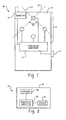
- Fig. 1 is a block diagram of a handheld audio processing device 10.
- the handheld audio processing device 10 comprises a plurality of microphones 12, a processing subsystem 14, and a transmitter 16.
- the handheld audio processing device 10 is designed to be held by a person in the vicinity of sounds that are to be received by the microphones 12 and processed.
- the plurality of microphones 12 are arranged on a surface 18 so that at least two pairs of the microphones 12 define intersecting axes 20 and 22 on the surface 18 of the handheld audio processing device 10.
- the intersecting axes 20 and 22 may intersect at an angle of 90 degrees as shown in Fig. 1.
- the plurality of microphones 12 may be omni directional microphones, but unidirectional microphones may also be used.
- the handheld audio processing device 10 includes a processing subsystem 14.
- the processing subsystem 14 is configured to receive audio signals that are generated from the plurality of microphones 12 and to spatially filter the audio signals.
- the processing subsystem 14 may be configured to spatially filter audio signals from a subset of the plurality of microphones 12 based either on a processing configuration in the processing subsystem 14 or on a user selection received via a user input 11.
- the transmitter 16 is configured to transmit the audio signals that are spatially filtered by the processing subsystem 14.
- the transmitter 16 may transmit the signals to an audio receiver unit 24, which is discussed in Fig. 2.
- Fig. 2 is a block diagram of an audio receiver unit 24.
- the audio receiver unit 24 may be a hearing aid.
- the audio receiver unit comprises an earpiece 26, a receiver 28, a processing subsystem 30, and a speaker 32.
- the earpiece 26 may be designed to fit within the ear, or alternatively, rest on the ear.
- the system may include two audio receiver units 24, each worn on a different ear.
- the receiver 28 and the processing subsystem 30 are designed to receive and process the spatially filtered audio signals transmitted by the handheld audio transmitter 26.
- the spatially filtered audio signals are received by the receiver 28 and are subsequently processed by the processing subsystem 30 to generate electrical signals to drive the speaker 32.
- the speaker 32 in turn, generates an acoustic signal heard by the user wearing the audio receiver unit 24.
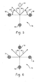
- Fig. 3 is an illustration of a microphone selection 34 to facilitate one sound pick-up strategy for spatially filtering audio signals.
- one microphone 40 is configured to be activated, and the other three microphones 36, 38 and 42 are not activated.
- the activated microphone 40 picks up omni directional sound in one direction, and the processing subsystem produces a monophonic audio signal which is transmitted to the audio receiver unit.
- an omni directional sound pick-up strategy can be implemented by activating more than one microphone, and summing the signals from the activated microphones.
- Fig. 4 is another illustration of a microphone selection 44 to facilitate another sound pick-up strategy for spatially filtering audio signals.
- This selection 44 can be used to produce a monophonic, first-order directional sound pickup pattern (beam).
- microphones 48 and 50 are configured to be activated, and microphones 46 and 52 are not activated.
- This first order sound pickup pattern is implemented by configuring microphone 48 as the front microphone and microphone 50 as the rear microphone.
- the optionally delayed signal from rear microphone 50 is subtracted from the signal from front microphone 48 to generate an audio signal with its main beam directed along line 54. It should be understood that various coincident pairs of microphones in the arrangement can be used to produce signals in directions other than direction 54.
- Fig. 5 is an illustration of a sound pick-up strategy 56 utilizing three of the four microphones in the arrangement.
- Microphones 58, 60 and 62 are activated, and microphone 64 is not activated.
- the microphones in this scenario can be used to generate two monophonic sound pick-up directions 66 and 68. Sounds picked-up along directions 66 and 68 can be transmitted to audio receiver units worn on alternate ears, creating stereophonic playback.
- microphone 58 is the front microphone and microphone 60 is the rear microphone. Subtracting rear microphone 60 from front microphone 58 generates the pickup beam 66 oriented 45 degrees to the right of the y-axis. This audio signal can be transmitted to the audio receiver unit located on the right ear of the listener.
- the left-ear sound signal in direction 68 is similarly generated.
- microphone 62 is the front microphone and microphone 60 is the rear microphone.
- the signal from rear microphone 60 is subtracted from the signal from the front microphone 62.
- the result is a pickup beam directed 45 degrees to the left of the y-axis 68, which can be transmitted to the audio receiver unit located on the left ear of the listener. Transmitting these signals to the left and right audio receiver units results in stereophonic sound for the listener.
- Signals in directions other than direction 68 and 66 can be similarly generated using different combinations of activated microphones 58, 60, 62 and 64.
- Fig. 6 is an illustration of a sound pick-up strategy 70 wherein all four microphones 72, 74, 76 and 78 in the arrangement are used to create stereophonic sound signals along directions 80 and 82.
- the audio signal along direction 82 can be generated by using microphone coincident pair 78 and 76, or by using microphone coincident pair 72 and 74.
- Activating all four microphones can generate two independent directional signals in the direction 82. Averaging these two independent directional signals can reduce the overall noise present in the microphone system. In one embodiment, the averaging of the signals is performed prior to the time delay and subtraction necessary to implement the directional pickup pattern. Similar processing can be performed to generate the audio signal in direction 80.
- the signal in direction 80 can be implemented by using either microphone coincident pair 72 and 78 or microphone coincident pair 74 and 76. It should be noted that signals can be generated in directions other than directions 80 and 82 by variations in the processing of the individual microphone signals.
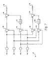
- Fig. 7 is a block diagram of an example microphone-signal averaging circuit 84 that can be used to implement the sound pickup strategy of Fig. 6.
- the term "element" used herein may refer to software, hardware, or a combination of software and hardware.
- the signals generated from microphone 72 are added to the signal from microphone 74 at summation element 88.
- the signals from microphone 76 and microphone 78 are added at summation element 90.
- the signal from summation element 90 is passed through a time delay element 92, and is subtracted from the signal from summation element 88 at difference element 94.
- the right stereophonic signal 96 is similarly generated.
- the signal from microphone 72 and the signal from microphone 78 are added at summation element 98.
- the signal from microphone 74 and the signal from microphone 76 are added at summation element 100.
- the signal from summation element 100 is then delayed at time delay element 102.
- the signal from time delay element 102 is subtracted from the signal from summation element 98 at difference element 104 to generate the right stereophonic signal 96.
- Fig. 8 is a block diagram of another sound pickup strategy that can be implemented using the microphone arrangement.
- the block diagram 106 depicts the four microphones in the arrangement in a gain optimized multiple microphone array for beam steering.
- a gain-optimized array can be implemented using any combination of two or more microphones.
- Filter elements 108, 110, 112 and 114 are configured to filter the signal generated by each of the four microphones.
- Each of the signals from the filters 108, 110, 112 and 114 are then added at summation elements 116, 118 and 120.
- the output of summation element 116 is the beam steered audio signal 122.
- Fig. 9 is a flowchart of an example method for receiving and processing audio signals 124.
- the process begins at step 126, where audio signals are received by the handheld audio processing device through the plurality of microphones on the surface of the handheld audio processing device.
- the audio signals are spatially filtered to generate a plurality of maximum response axes.
- the maximum response axes are generated by spatially filtering the signals from the plurality of microphones that are present in the microphone arrangement on the handheld audio processing device.
- step 130 one or more of the plurality of maximum response axes that were generated in step 84 are selected. From the maximum response axes that are selected, one or more selectively steered audio signals is generated. The selection may be based on a default selection and position of the microphones if no user selection is made. Alternatively, the selection may be made by a user. In step 132, the audio signals are transmitted.
- an audio receiver unit receives the selectively steered audio signals transmitted by the handheld audio processing device.
- the audio receiver unit may be a hearing aid embedded in the ear of a listener.
- Fig. 10 is a flowchart illustrating an example of a method for receiving and processing audio signals 136.
- step 138 audio signals are received from the coincident pairs of microphones located on the handheld audio processing device.
- step 140 the handheld audio processing device generates stereophonic audio signals from the audio signals received from the coincident pairs of microphones in step 138.
- step 142 the stereophonic audio signals generated in step 140 are transmitted to a pair of hearing instruments located remote from the handheld audio processing unit.
Landscapes
- Health & Medical Sciences (AREA)
- Otolaryngology (AREA)
- Physics & Mathematics (AREA)
- Engineering & Computer Science (AREA)
- Acoustics & Sound (AREA)
- Signal Processing (AREA)
- Circuit For Audible Band Transducer (AREA)
- Obtaining Desirable Characteristics In Audible-Bandwidth Transducers (AREA)
Applications Claiming Priority (1)
| Application Number | Priority Date | Filing Date | Title |
|---|---|---|---|
| US11/481,171 US20080008339A1 (en) | 2006-07-05 | 2006-07-05 | Audio processing system and method |
Publications (1)
| Publication Number | Publication Date |
|---|---|
| EP1876864A2 true EP1876864A2 (fr) | 2008-01-09 |
Family
ID=38565900
Family Applications (1)
| Application Number | Title | Priority Date | Filing Date |
|---|---|---|---|
| EP07012947A Withdrawn EP1876864A2 (fr) | 2006-07-05 | 2007-07-02 | Système et procédé de traitement audio |
Country Status (3)
| Country | Link |
|---|---|
| US (1) | US20080008339A1 (fr) |
| EP (1) | EP1876864A2 (fr) |
| JP (1) | JP2008017469A (fr) |
Cited By (1)
| Publication number | Priority date | Publication date | Assignee | Title |
|---|---|---|---|---|
| WO2009109217A1 (fr) * | 2008-03-03 | 2009-09-11 | Nokia Corporation | Appareil de capture et de rendu d'une pluralité de canaux audio |
Families Citing this family (26)
| Publication number | Priority date | Publication date | Assignee | Title |
|---|---|---|---|---|
| JP2015097385A (ja) * | 2013-10-22 | 2015-05-21 | ジーエヌ リザウンド エー/エスGn Resound A/S | 中断可能なマイクロフォン電源を有する聴覚機器 |
| US9467765B2 (en) | 2013-10-22 | 2016-10-11 | Gn Resound A/S | Hearing instrument with interruptable microphone power supply |
| US9565493B2 (en) | 2015-04-30 | 2017-02-07 | Shure Acquisition Holdings, Inc. | Array microphone system and method of assembling the same |
| US9554207B2 (en) | 2015-04-30 | 2017-01-24 | Shure Acquisition Holdings, Inc. | Offset cartridge microphones |
| US10367948B2 (en) | 2017-01-13 | 2019-07-30 | Shure Acquisition Holdings, Inc. | Post-mixing acoustic echo cancellation systems and methods |
| WO2018140618A1 (fr) | 2017-01-27 | 2018-08-02 | Shure Acquisiton Holdings, Inc. | Module et système de microphone en réseau |
| CN112335261B (zh) | 2018-06-01 | 2023-07-18 | 舒尔获得控股公司 | 图案形成麦克风阵列 |
| US11297423B2 (en) | 2018-06-15 | 2022-04-05 | Shure Acquisition Holdings, Inc. | Endfire linear array microphone |
| US11310596B2 (en) | 2018-09-20 | 2022-04-19 | Shure Acquisition Holdings, Inc. | Adjustable lobe shape for array microphones |
| US11109133B2 (en) | 2018-09-21 | 2021-08-31 | Shure Acquisition Holdings, Inc. | Array microphone module and system |
| US11303981B2 (en) | 2019-03-21 | 2022-04-12 | Shure Acquisition Holdings, Inc. | Housings and associated design features for ceiling array microphones |
| US11558693B2 (en) | 2019-03-21 | 2023-01-17 | Shure Acquisition Holdings, Inc. | Auto focus, auto focus within regions, and auto placement of beamformed microphone lobes with inhibition and voice activity detection functionality |
| JP7572964B2 (ja) | 2019-03-21 | 2024-10-24 | シュアー アクイジッション ホールディングス インコーポレイテッド | 阻止機能を伴うビーム形成マイクロフォンローブの自動集束、領域内自動集束、および自動配置 |
| TW202101422A (zh) | 2019-05-23 | 2021-01-01 | 美商舒爾獲得控股公司 | 可操縱揚聲器陣列、系統及其方法 |
| WO2020243471A1 (fr) | 2019-05-31 | 2020-12-03 | Shure Acquisition Holdings, Inc. | Automélangeur à faible latence, à détection d'activité vocale et de bruit intégrée |
| CN114467312A (zh) | 2019-08-23 | 2022-05-10 | 舒尔获得控股公司 | 具有改进方向性的二维麦克风阵列 |
| US12028678B2 (en) | 2019-11-01 | 2024-07-02 | Shure Acquisition Holdings, Inc. | Proximity microphone |
| US11552611B2 (en) | 2020-02-07 | 2023-01-10 | Shure Acquisition Holdings, Inc. | System and method for automatic adjustment of reference gain |
| US11706562B2 (en) | 2020-05-29 | 2023-07-18 | Shure Acquisition Holdings, Inc. | Transducer steering and configuration systems and methods using a local positioning system |
| JP7814400B2 (ja) | 2021-01-28 | 2026-02-16 | シュアー アクイジッション ホールディングス インコーポレイテッド | ハイブリッドオーディオビーム形成システム |
| US12452584B2 (en) | 2021-01-29 | 2025-10-21 | Shure Acquisition Holdings, Inc. | Scalable conferencing systems and methods |
| US12542123B2 (en) | 2021-08-31 | 2026-02-03 | Shure Acquisition Holdings, Inc. | Mask non-linear processor for acoustic echo cancellation |
| US12289584B2 (en) | 2021-10-04 | 2025-04-29 | Shure Acquisition Holdings, Inc. | Networked automixer systems and methods |
| EP4427465A1 (fr) | 2021-11-05 | 2024-09-11 | Shure Acquisition Holdings, Inc. | Algorithme distribué pour auto-mélange de la parole sur des réseaux sans fil |
| US12250526B2 (en) | 2022-01-07 | 2025-03-11 | Shure Acquisition Holdings, Inc. | Audio beamforming with nulling control system and methods |
| US12598261B2 (en) | 2022-09-28 | 2026-04-07 | Shure Acquisition Holdings, Inc. | Wideband doubletalk detection for optimization of acoustic echo cancellation |
Family Cites Families (1)
| Publication number | Priority date | Publication date | Assignee | Title |
|---|---|---|---|---|
| JP3789685B2 (ja) * | 1999-07-02 | 2006-06-28 | 富士通株式会社 | マイクロホンアレイ装置 |
-
2006
- 2006-07-05 US US11/481,171 patent/US20080008339A1/en not_active Abandoned
-
2007
- 2007-06-28 JP JP2007170551A patent/JP2008017469A/ja active Pending
- 2007-07-02 EP EP07012947A patent/EP1876864A2/fr not_active Withdrawn
Cited By (2)
| Publication number | Priority date | Publication date | Assignee | Title |
|---|---|---|---|---|
| WO2009109217A1 (fr) * | 2008-03-03 | 2009-09-11 | Nokia Corporation | Appareil de capture et de rendu d'une pluralité de canaux audio |
| CN101960865A (zh) * | 2008-03-03 | 2011-01-26 | 诺基亚公司 | 用于捕获和呈现多个音频声道的装置 |
Also Published As
| Publication number | Publication date |
|---|---|
| US20080008339A1 (en) | 2008-01-10 |
| JP2008017469A (ja) | 2008-01-24 |
Similar Documents
| Publication | Publication Date | Title |
|---|---|---|
| EP1876864A2 (fr) | Système et procédé de traitement audio | |
| US11064302B2 (en) | Method and apparatus for a binaural hearing assistance system using monaural audio signals | |
| EP3468228B1 (fr) | Système auditif binauriculaire comportant une localisation des sources sonores | |
| EP3013070B1 (fr) | Système auditif | |
| US9930456B2 (en) | Method and apparatus for localization of streaming sources in hearing assistance system | |
| JP6092151B2 (ja) | 空間的に信号を強調する補聴器 | |
| US9641942B2 (en) | Method and apparatus for hearing assistance in multiple-talker settings | |
| US7167571B2 (en) | Automatic audio adjustment system based upon a user's auditory profile | |
| US10349191B2 (en) | Binaural gearing system and method | |
| US20080205659A1 (en) | Method for improving spatial perception and corresponding hearing apparatus | |
| JP6193844B2 (ja) | 選択可能な知覚空間的な音源の位置決めを備える聴覚装置 | |
| CN112544089A (zh) | 提供具有空间背景的音频的麦克风设备 | |
| US8666080B2 (en) | Method for processing a multi-channel audio signal for a binaural hearing apparatus and a corresponding hearing apparatus | |
| EP2826262B1 (fr) | Procédé pour commander le fonctionnement d'une prothèse auditive, et prothèse auditive correspondante | |
| CN105744455A (zh) | 用于在外部拾取的麦克风信号上叠加空间听觉提示的方法 | |
| EP2887695B1 (fr) | Dispositif d'audition à positionnement spatial perçu sélectionnable de sources acoustiques | |
| US20240267681A1 (en) | Bone-conductive audio system |
Legal Events
| Date | Code | Title | Description |
|---|---|---|---|
| PUAI | Public reference made under article 153(3) epc to a published international application that has entered the european phase |
Free format text: ORIGINAL CODE: 0009012 |
|
| 17P | Request for examination filed |
Effective date: 20070702 |
|
| AK | Designated contracting states |
Kind code of ref document: A2 Designated state(s): AT BE BG CH CY CZ DE DK EE ES FI FR GB GR HU IE IS IT LI LT LU LV MC MT NL PL PT RO SE SI SK TR |
|
| AX | Request for extension of the european patent |
Extension state: AL BA HR MK YU |
|
| RAP1 | Party data changed (applicant data changed or rights of an application transferred) |
Owner name: SOUND DESIGN TECHNOLOGIES LTD. |
|
| STAA | Information on the status of an ep patent application or granted ep patent |
Free format text: STATUS: THE APPLICATION HAS BEEN WITHDRAWN |
|
| 18W | Application withdrawn |
Effective date: 20090625 |