EP1877218B1 - Verfahren zur reparatur einer mit einem gewinde versehenen generatorrotorgebläseanordnung - Google Patents
Verfahren zur reparatur einer mit einem gewinde versehenen generatorrotorgebläseanordnung Download PDFInfo
- Publication number
- EP1877218B1 EP1877218B1 EP06737404A EP06737404A EP1877218B1 EP 1877218 B1 EP1877218 B1 EP 1877218B1 EP 06737404 A EP06737404 A EP 06737404A EP 06737404 A EP06737404 A EP 06737404A EP 1877218 B1 EP1877218 B1 EP 1877218B1
- Authority
- EP
- European Patent Office
- Prior art keywords
- collar
- threads
- generator
- blade
- diameter
- Prior art date
- Legal status (The legal status is an assumption and is not a legal conclusion. Google has not performed a legal analysis and makes no representation as to the accuracy of the status listed.)
- Expired - Lifetime
Links
Images


Classifications
-
- F—MECHANICAL ENGINEERING; LIGHTING; HEATING; WEAPONS; BLASTING
- F01—MACHINES OR ENGINES IN GENERAL; ENGINE PLANTS IN GENERAL; STEAM ENGINES
- F01D—NON-POSITIVE DISPLACEMENT MACHINES OR ENGINES, e.g. STEAM TURBINES
- F01D5/00—Blades; Blade-carrying members; Heating, heat-insulating, cooling or antivibration means on the blades or the members
- F01D5/005—Repairing methods or devices
-
- B—PERFORMING OPERATIONS; TRANSPORTING
- B23—MACHINE TOOLS; METAL-WORKING NOT OTHERWISE PROVIDED FOR
- B23P—METAL-WORKING NOT OTHERWISE PROVIDED FOR; COMBINED OPERATIONS; UNIVERSAL MACHINE TOOLS
- B23P6/00—Restoring or reconditioning objects
- B23P6/002—Repairing turbine components, e.g. moving or stationary blades, rotors
- B23P6/005—Repairing turbine components, e.g. moving or stationary blades, rotors using only replacement pieces of a particular form
-
- F—MECHANICAL ENGINEERING; LIGHTING; HEATING; WEAPONS; BLASTING
- F01—MACHINES OR ENGINES IN GENERAL; ENGINE PLANTS IN GENERAL; STEAM ENGINES
- F01D—NON-POSITIVE DISPLACEMENT MACHINES OR ENGINES, e.g. STEAM TURBINES
- F01D5/00—Blades; Blade-carrying members; Heating, heat-insulating, cooling or antivibration means on the blades or the members
- F01D5/30—Fixing blades to rotors; Blade roots ; Blade spacers
- F01D5/3023—Fixing blades to rotors; Blade roots ; Blade spacers of radial insertion type, e.g. in individual recesses
-
- F—MECHANICAL ENGINEERING; LIGHTING; HEATING; WEAPONS; BLASTING
- F04—POSITIVE - DISPLACEMENT MACHINES FOR LIQUIDS; PUMPS FOR LIQUIDS OR ELASTIC FLUIDS
- F04D—NON-POSITIVE-DISPLACEMENT PUMPS
- F04D29/00—Details, component parts, or accessories
- F04D29/26—Rotors specially for elastic fluids
- F04D29/32—Rotors specially for elastic fluids for axial flow pumps
- F04D29/321—Rotors specially for elastic fluids for axial flow pumps for axial flow compressors
- F04D29/322—Blade mountings
-
- F—MECHANICAL ENGINEERING; LIGHTING; HEATING; WEAPONS; BLASTING
- F04—POSITIVE - DISPLACEMENT MACHINES FOR LIQUIDS; PUMPS FOR LIQUIDS OR ELASTIC FLUIDS
- F04D—NON-POSITIVE-DISPLACEMENT PUMPS
- F04D29/00—Details, component parts, or accessories
- F04D29/26—Rotors specially for elastic fluids
- F04D29/32—Rotors specially for elastic fluids for axial flow pumps
- F04D29/34—Blade mountings
Definitions
- This invention relates to a method of repairing a rotor blade and a generator hub.
- the invention relates in general to electrical generators and in particular to a method of repairing a threaded aluminum rotor blower blade connection.
- Blower blades of a combustion turbine's electrical generator may be connected to rotors in a variety of ways including that described in U.S. Pat. No. 5,073,087 . That patent discloses that a plurality of blades may be inserted within a respective plurality of slots formed within radially projecting regions machined within the outer surface of a blower hub.
- the slots may be formed as dovetails and may be dimensioned so that the length of each slot is only slightly greater than the corresponding dimension of each blade root.
- the blades may be replaced by unwrapping a band wrapped around a groove adjacent a slot and held in place with adhesive then sliding the defective blade from the slot. A new blade may then be inserted into the slot.
- US-A-3 073 569 discloses a blade mounting arrangement for an axial fluid flow machine, such as a turbine or compressor.
- a blade of the axial flow type has an airfoil shaped vane portion, a platform portion and an externally threaded root portion.
- a plurality of such blades are disposed in an annular row about the periphery of a rotor structure.
- the rotor structure is provided with an annular array of threaded bores, extending radially, for retaining the blades.
- An intermediate sleeve member is provided having internal and external threads that cooperate respectively with the root portion of a blade and a rotor structure bore.
- GB 451 518 A discloses a variable pitch airscrew blade of light metal which has a sleeve of harder metal threaded on to the blade root and positively locked thereto at its inner end by a plate member which abuts against the end of the blade root and is secured thereto by members screwed into the end of the blade root and has serrations which engage corresponding serrations on the sleeve.
- US-A-4 730 968 discloses a self-tapping, self-aligning thread repair insert.
- the insert is an annular sleeve having a threaded interior surface, a partially threaded exterior surface, and an opening.
- the exterior surface has a tapered portion between a straight threaded portion and a straight thread-free portion.
- the thread-free portion and the opening are adjacent an end of the sleeve.
- the thread-free portion is free of threads for a distance of at least 1.5 thread widths from the end of the sleeve.
- the sleeve is made of a 400 series stainless steel. The sleeve is case hardened.
- a method of repairing a rotor blade and a generator hub from which the rotor blade has been removed, the rotor blade having fatigued material in threads of a threaded blade root comprising: removing at least a portion of the fatigued material to form the blade root to a first diameter; forming threads on the first diameter of the blade root; securing a collar within a hole formed in the generator hub, the collar comprising internal threads for receiving the threads formed on the first diameter of the blade root; and threading the blade root of the rotor blade into the collar.
- Embodiments of the invention allow for repairing an aluminum blade root and generator blower hub assembly.
- the root of the blade is threaded and inserted into a corresponding set of threads formed in the hub. Inspection of threaded aluminum blades has occasionally revealed that cracks have formed near the top threads. This may be attributed to fatigue within the aluminum caused by operating stresses exerted on the blade. Standard maintenance procedures typically require the blades having cracks to be replaced. However, replacing blades is time consuming and costly especially if replacement blades are in short supply, which may cause long outages at a gas turbine power plant.
- Embodiments of the invention allow for stripping away fatigued material on an aluminum component and roll forming threads on the component that exhibit an increased fatigue resistance.
- a threaded sleeve or collar comprising a steel alloy may be provided in combination with the newly formed threads on the aluminum component to further increase fatigue resistance of the threaded connection.
- a relief groove may be formed within the collar.
- Embodiments of the invention provide improved fatigue resistance within the blade root during operation of a generator.
- Nonferrous generator rotor blades which may be fabricated of aluminum, for example.
- Ferrous materials exhibit a definite fatigue limit whereas nonferrous metals such as aluminum, copper and others do not demonstrate a fatigue limit.
- a ferrous material such as a steel alloy component
- it may never break.
- This is attributable to a fatigue limit exhibited by the steel alloy, i.e., there is a limiting stress level property of the steel alloy below which the steel will never break.
- nonferrous metals accumulate fatigue stress so that even if such metals are subjected to the smallest stress levels, eventually they will break. These nonferrous materials do not exhibit a fatigue limit.
- Embodiments of the invention are advantageous in that they reestablish a fatigue limit within an assembly having an aluminum component that has become cracked or contains fatigued material.
- Such an assembly may include an aluminum blade 10 having an aluminum blade root 14 as shown in FIG. 1A .
- Blade 10 is connected to a steel blower hub 12, which may be a hub of a rotor used with a gas turbine generator (not shown).
- gas turbine generator not shown.
- Such electrical generators are sold by the assignee of the present invention and may be ones that use threaded aluminum blades 10. These generators utilize single-stage blowers, but embodiments of the invention may be used with multi-stage blowers and other apparatus.
- Blade 10 may be made of aluminum and have an externally threaded blade root 14 threaded to mate with an internally threaded countersunk hole 16 formed within hub 12. A plurality of blades 10 may be circumferentially disposed around hub 12 to form a row of blades as will be recognized by those skilled in the art.
- FIG. 1 B illustrates blade root 14 having a nominal thread diameter "d" when originally threaded into hub 12.
- FIG. 2A illustrates a cross sectional view of an exemplary attachment or collar 20 that may be used in a method of repairing blade 10, such as when a blade 10 develops cracks in the threads during generator operation.
- Collar 20 may be fabricated of a steel alloy and formed as a steel sleeve threaded in both the internal "d1" and external "d2" diameters. Fabricating collar 20 of a steel alloy is advantageous because of the fatigue limiting properties exhibited by such alloys. Collar 20 will absorb fatigue loading during operation of a generator. Internally threaded diameter "d1" may be smaller than the original thread diameter "d" of blade root 14 and externally threaded diameter "d2" may be greater than the original thread diameter "d” of blade root 14.
- Collar 20 may be fabricated of a steel alloy having a sufficient strength and fatigue limit to hold blade 10 in blower hub 12 after blade root 14 has been repaired and reassembled into hub 12.
- the strength and fatigue limit of collar 20 may be determined based on the operating specifications of the generator within which collar 20 will be used as well as other design criteria recognized by those skilled in the art.
- Collar 20 may have a minimum diameter that for which (a) the nominal stresses in the blade root 14 due to centrifugal force of blade 10 during operation do not exceed design requirements and (b) the maximum concentrated stress in the threads of collar 20 does not result in failure due to fatigue in a number of cycles below design requirements.
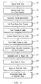
- FIG. 3 illustrates a flow diagram of an exemplary method of repairing blade 10 and the generator blower hub assembly incorporating blade 10.
- blade 10 may be removed from hub 12 and inspected using known techniques to determine whether an unacceptable amount of cracking has developed in threaded blade root 14. If blade root 14 is to be repaired, step 32 allows for the external diameter "d" of root 14 ( FIG. 1B ) to be machined to eliminate any cracks or material that may be unacceptably fatigued. Blade root 14 may be machined to a new diameter to remove fatigued material. The blade root 14 may be inspected using known techniques to verify that unacceptable cracking is not present after machining.
- Blades 10 may have different design specifications and operating characteristics. This causes varying loads and stresses to be placed on blades 10 used in different generator setups.
- the threads used for attaching a blade 10 to a hub 12 may vary from generator-to-generator, and from blade-to-blade within a single generator.
- Step 34 allows for determining the thread specifications for a blade root 14 and an associated collar 20, which may be used to determine the new diameter of the blade root 14 machined in step 32.
- Thread specifications may be determined for externally threading blade root 14, and the internal threads 35 and external threads 37 to be formed on collar 20. These thread specifications may be calculated to improve the fatigue resistance of blade root 14 when assembled into collar 20 and hub 12 relative to the fatigue resistance of the original threads formed on blade root 14.
- the lead and root diameters, lead and pitch of the threads for blade root 14 and collar 20 may be a function of a generator's operating conditions and a blade's 10 design specifications and performance characteristics.
- Blade root 14 may be threaded using known techniques and in an embodiment may be threaded with Acme threads determined in step 34. Blade root 14 may be threaded to a determined thread diameter "d7". Step 36 allows for threads to be formed on blade root 14 by roll forming. Alternate embodiments allow for forming threads by cutting. It has been determined by the inventors of the present invention that roll forming threads on blade root 14 creates threads that are stronger and less prone to fatigue than threads that are formed by cutting. Threads may be roll formed on blade root 14 so that the center cold fusion does not extend deeper than approximately 75% of the basic thread height. Embodiments allow for roll forming threads on blade root 14, which are stronger and more fatigue resistant than cut threads.
- Blade root 14 may be machined and threaded to different diameters depending on operating specifications and in an embodiment the major threaded diameter of blade root 14 may be between about 45mm and 60mm. Blade root 14 may have a minimum diameter that for which (a) the nominal stresses in the blade root 14 due to centrifugal force of blade 10 during operation do not exceed design requirements and (b) the maximum concentrated stress in the threads of blade root 14 does not result in failure due to fatigue in a number of cycles below design requirements.
- the threads determined in step 34 may be formed in collar 20 in step 38.
- Internal threads 35 may be formed to thread diameter "d1" and external threads 37 to thread diameter "d2". Threads may be formed in collar 20 by roll forming or cutting as appreciated by those skilled in the art.
- collar 20 may be provided with a geometry calculated to improve the fatigue resistance of blade root 14 when reassembled into hub 12.
- a geometry may include providing a face of collar 20 with a relief groove 40, as shown in FIGS. 2A and 2B .
- Relief groove 40 may be sized to distribute stresses or loads more evenly across all threads formed in collar 20 than in the absence of such a groove.
- Relief groove 40 may reduce the stresses being concentrated in the top threads of collar 20 during generator operation. This improves fatigue resistance and reduces the risk of cracks being initiated in blade root 14 and/or collar 20 during generator operation.
- Relief groove 40 may be optimized in step 42 as a function of the thread specifications determined in step 34, the material used for making and dimensions of collar 20 and the performance characteristics of blade 10.
- Relief groove 40 may be added to collar 20 in step 44 using known techniques, such as by cutting. Embodiments allow for groove 40 to be formed as a continuous groove around the circumference in a top end of collar 20 as shown in FIG. 2B . In alternate embodiments relief groove 40 may be discontinuous to form a plurality of discrete slots or grooves intermittently spaced around the top end of collar 20. One or more relief grooves 40 may be formed directly in hub 12 instead of or in addition to ones formed in collar 20.
- Step 50 allows for machining the internal diameter "d" of the existing threaded hole in hub 12 with a counterbore and new diameter "d2" for receipt of collar 20.
- New diameter "d2" may be threaded with new threads such as the Acme threads determined in step 34.
- Collar 20 may be assembled with blower hub 14 in step 52 and torqued or preloaded to required design specifications. Preloading collar 20 may be calculated based on the specific material from which collar 20 and hub 12 are fabricated, as well as the expected load produced from centrifugal forces of collar 20 and blade 10 during operation. Collar 20 may be locked in place in step 54 by staking collar 20 in blower hub 14 at two notches formed in collar 20 or in other suitable manners. In alternate embodiments, collar 20 may be threaded back into the original threads formed in hub 12 so that the originally threaded hole would not have to be machined and new threads would not have to be formed therein.
- Blade 10 may be assembled with collar 20 in step 56 by turning blade 10 into collar 20 via their respective threads until reaching the original specification of blade tip diameter and airfoil angle.
- the threads formed on blade root 14 are not preloaded when blade 10 is threaded into collar 20.
- the threads 35, 37 of collar 20 may be covered with LOCTITE brand adhesive or other conventional substances to increase friction and minimize motion of blade 10 relative to collar 20 and hub 12.
- FIG. 4 illustrates a blade 10 assembled with collar 20 in hub 12. After completing assembly of all blades 10 to hub 12 via respective collars 20, the hub 12 is reassembled to the generator rotor (not shown). The generator rotor is then balanced to account for any changes in weight attributed to the repair process such as weight being added by virtue of one or more collars 20 be assembled to hub 12.
Landscapes
- Engineering & Computer Science (AREA)
- Mechanical Engineering (AREA)
- General Engineering & Computer Science (AREA)
- Manufacture Of Motors, Generators (AREA)
- Motor Or Generator Cooling System (AREA)
- Structures Of Non-Positive Displacement Pumps (AREA)
Claims (13)
- Verfahren zur Reparatur eines Rotorblatts (10) und einer Generatornabe (12), aus der das Rotorblatt (10) entfernt wurde, wobei das Rotorblatt (10) ermüdetes Material in den Gewinden eines mit einem Gewinde versehenen Rotorblattfußes (14) aufweist, wobei das Verfahren folgendes umfasst:Entfernen (32) mindestens eines Teils des ermüdeten Materials, um den Rotorblattfuß (14) auf einen ersten Durchmesser zu formen;Ausbilden (36) von Gewinden auf dem ersten Durchmesser des Rotorblattfußes (14);Befestigen (52) einer Manschette (20) in einem Loch (16), das in der Generatornabe (12) ausgebildet ist, wobei die Manschette (20) Innengewinde (35) umfasst, um die an dem ersten Durchmesser des Rotorblattfußes (14) ausgebildeten Gewinde aufzunehmen; undEinschrauben (56) des Rotorblattfußes (14) des Rotorblatts (10) in die Manschette (20).
- Verfahren gemäß Anspruch 1, welches ferner folgendes umfasst:mechanisches Bearbeiten (50) des Lochs (16), das in der Generatornabe (12) ausgebildet ist, zu einem zweiten Durchmesser;Ausbilden (50) von Gewinden auf dem zweiten Durchmesser;Ausbilden (38) von Außengewinden (37) an der Manschette (20); undBefestigen (52) der Manschette (20) in dem Loch (16), das in der Generatornabe (12) ausgebildet ist, indem die Manschette (20) in das Loch (16) eingeschraubt wird.
- Verfahren gemäß Anspruch 1, welches ferner folgendes umfasst:Ausbilden (36) von Gewinden auf dem ersten Durchmesser, die derart berechnet sind, dass sie eine Ermüdungsfestigkeit erzeugen, die größer ist als eine Ermüdungsfestigkeit, die durch die Gewinde des mit einem Gewinde versehenen Rotorblattfußes (14) erzielt wurde, der aus der Generatornabe (12) entfernt wurde.
- Verfahren gemäß Anspruch 3, welches ferner folgendes umfasst:Rollformen (36) von Gewinden an dem ersten Durchmesser, sodass ein mittlerer Kaltfusionsteil eines Großteils der rollgeformten Gewinde sich nicht tiefer erstreckt als ungefähr 75 % einer Höhe der jeweiligen rollgeformten Gewinde.
- Verfahren gemäß Anspruch 1, welches ferner folgendes umfasst:Fräsen (44) einer Reliefnut (40) in eine Stirnfläche der Manschette (20).
- Verfahren gemäß Anspruch 1, welches ferner folgendes umfasst:Ausbilden (36) von Gewinden auf dem ersten Durchmesser, die derart berechnet sind, dass sie eine Ermüdungsfestigkeit erzeugen, die größer ist als eine Ermüdungsfestigkeit, die durch die Gewinde des mit einem Gewinde versehenen Rotorblattfußes (14) erzielt wurde, der aus der Generatornabe (12) entfernt wurde;Bereitstellen der Manschette (20), die aus einer Stahllegierung besteht;Ausbilden (38) von Außengewinden (37) auf der Manschette (20);Ausbilden (38) von Innengewinden (35) auf der Manschette (20); undBefestigen (52) der Manschette (20) in dem Loch (16), das in der Generatornabe (12) ausgebildet wurde, durch Einschrauben der Manschette (20) in die Innengewinde in dem Loch (16).
- Verfahren gemäß Anspruch 1, welches ferner folgendes umfasst:Bereitstellen der Manschette (20), die aus einer Stahllegierung besteht; undder auf dem ersten Durchmesser des Rotorblattfußes (14) ausgebildeten Gewinde, die aus Aluminium bestehen.
- Verfahren gemäß Anspruch 7, welches ferner folgendes umfasst:Bereitstellen (44) der Manschette (20), welche eine Reliefnut (40) aufweist, die in eine Stirnfläche der Manschette (20) gefräst ist.
- Verfahren gemäß Anspruch 1, welches ferner folgendes umfasst:Rollformen (36) von Gewinden auf dem ersten Durchmesser.
- Verfahren zur Reparatur einer Generatorgebläsenabenanordnung (12) eines Generators, wobei das Verfahren folgendes umfasst:Ausbauen der Generatorgebläsenabenanordnung (12) aus einem Generatorrotor;Entfernen (30) mindestens eines Rotorblatts (10) aus einem mit einem Gewinde versehenen Loch (16) in der Generatorgebläsenabenanordnung (12); undAusführen des Verfahrens gemäß einem der vorstehenden Ansprüche, um die Generatorgebläsenabenanordnung (12) zu reparieren, aus der das mindestens eine Rotorblatt (10) entfernt wurde.
- Verfahren gemäß Anspruch 10, wenn abhängig von Anspruch 2, welches ferner folgendes umfasst:Wiedereinbauen (58) der Generatorgebläsenabenanordnung (12) in den Generatorrotor; undAusbalancieren des Generatorrotors.
- Verfahren gemäß Anspruch 10, wenn abhängig von Anspruch 1, welches ferner folgendes umfasst:Bereitstellen der Manschette (20), die aus einer Stahllegierung besteht;Versehen (44) der Manschette (20) mit einer Geometrie, die dafür berechnet ist, eine Ermüdungsfestigkeit des Rotorblattfußes (14) des mindestens einen Rotorblatts (10), das aus der Generatorgebläsenabenanordnung (12) ausgebaut wurde, zu verbessern, wenn dieses wieder in die Generatorgebläsenabenanordnung (12) eingebaut wird.
- Verfahren gemäß Anspruch 12, welches ferner folgendes umfasst:Die Geometrie umfasst eine Reliefnut (40), die in der Manschette (20) ausgebildet ist.
Applications Claiming Priority (2)
| Application Number | Priority Date | Filing Date | Title |
|---|---|---|---|
| US11/122,569 US7431565B2 (en) | 2005-05-05 | 2005-05-05 | Method of repairing a threaded generator rotor blower assembly |
| PCT/US2006/008228 WO2006121499A1 (en) | 2005-05-05 | 2006-03-08 | Method of repairing a threaded generator rotor blower assembly |
Publications (2)
| Publication Number | Publication Date |
|---|---|
| EP1877218A1 EP1877218A1 (de) | 2008-01-16 |
| EP1877218B1 true EP1877218B1 (de) | 2009-09-16 |
Family
ID=36580031
Family Applications (1)
| Application Number | Title | Priority Date | Filing Date |
|---|---|---|---|
| EP06737404A Expired - Lifetime EP1877218B1 (de) | 2005-05-05 | 2006-03-08 | Verfahren zur reparatur einer mit einem gewinde versehenen generatorrotorgebläseanordnung |
Country Status (5)
| Country | Link |
|---|---|
| US (1) | US7431565B2 (de) |
| EP (1) | EP1877218B1 (de) |
| AT (1) | ATE442936T1 (de) |
| DE (1) | DE602006009246D1 (de) |
| WO (1) | WO2006121499A1 (de) |
Cited By (1)
| Publication number | Priority date | Publication date | Assignee | Title |
|---|---|---|---|---|
| US10527056B2 (en) | 2015-12-09 | 2020-01-07 | General Electric Company | Method for repairing a generator rotor blade connection |
Families Citing this family (9)
| Publication number | Priority date | Publication date | Assignee | Title |
|---|---|---|---|---|
| US7677870B1 (en) * | 2005-09-16 | 2010-03-16 | Florida Turbine Techologies, Inc. | Screw in blade/vane |
| EP1953339A1 (de) * | 2006-11-21 | 2008-08-06 | Siemens Aktiengesellschaft | Verfahren zur Reparatur eines Turbinenlaufrades |
| US8075280B2 (en) * | 2008-09-08 | 2011-12-13 | Siemens Energy, Inc. | Composite blade and method of manufacture |
| FR2956054B1 (fr) * | 2010-02-10 | 2012-04-27 | Snecma | Procede de reparation d'une bride d'un carter |
| FR2971177B1 (fr) * | 2011-02-03 | 2014-09-26 | Snecma | Procede de mise au point d'une gamme de polissage ou de rayonnage par tribofinition |
| EP2574723A1 (de) * | 2011-09-30 | 2013-04-03 | Alstom Technology Ltd | Nachrüstungsverfahren für Dampfturbine und zugehörige Vorrichtung |
| US9534499B2 (en) * | 2012-04-13 | 2017-01-03 | Caterpillar Inc. | Method of extending the service life of used turbocharger compressor wheels |
| BE1023290B1 (fr) * | 2015-07-22 | 2017-01-24 | Safran Aero Boosters S.A. | Aube composite de compresseur de turbomachine axiale |
| KR102095033B1 (ko) * | 2017-05-30 | 2020-03-30 | 두산중공업 주식회사 | 베인 링 조립체 및 이를 포함하는 압축기, 가스터빈 |
Family Cites Families (16)
| Publication number | Priority date | Publication date | Assignee | Title |
|---|---|---|---|---|
| GB451518A (en) | 1935-03-08 | 1936-08-07 | Albert George Elliott | Improvements in variable pitch airscrews |
| GB880281A (en) | 1959-08-14 | 1961-10-18 | Sulzer Ag | Mountings of adjustable rotor blades in axial flow turbines or compressors |
| US3073569A (en) * | 1959-12-01 | 1963-01-15 | Westinghouse Electric Corp | Blade mounting structure for a fluid flow machine |
| US4165904A (en) * | 1975-04-07 | 1979-08-28 | W. R. Grace & Co. | Wheel adaptor device |
| US4043239A (en) * | 1976-01-16 | 1977-08-23 | General Motors Corporation | Shim nut and screw bolt assembly |
| US4087896A (en) * | 1976-09-17 | 1978-05-09 | Paul R. Briles | Sleeve bolt installation nut |
| US4275263A (en) * | 1979-08-03 | 1981-06-23 | The United States Of America As Represented By The Secretary Of The Air Force | Electrically insulating structurally strong bushing assembly |
| US4312145A (en) * | 1980-01-09 | 1982-01-26 | Caterpillar Tractor Co. | Replaceable fastener for cover plates and the like |
| US4730968A (en) * | 1986-09-08 | 1988-03-15 | David Diperstein | Self-tapping, self-aligning thread repair insert |
| FR2620178B1 (fr) * | 1987-09-09 | 1990-01-19 | Aerospatiale | Dispositif d'attache a douilles, et pale de rotor munie d'un tel dispositif d'attache a un moyeu |
| US5073087A (en) * | 1990-04-13 | 1991-12-17 | Westinghouse Electric Corp. | Generator blower rotor structure |
| US5152556A (en) * | 1990-12-24 | 1992-10-06 | Kaiser Aerospace And Electronics Corporation | High temperature tubing joint with threaded, split collar |
| DE4332148C1 (de) | 1993-09-17 | 1995-02-02 | Siemens Ag | Vorrichtung zum Befestigen eines Schaftes am Umfang eines Trägerkörpers |
| US5788440A (en) * | 1997-03-05 | 1998-08-04 | Andronica; Ronald | Threaded adapter bushing |
| US6050610A (en) * | 1997-05-20 | 2000-04-18 | Hydril Company | Stress reduction groove for tubular connection |
| US6685236B2 (en) * | 2002-06-28 | 2004-02-03 | Weatherford/Lamb, Inc. | Helically wound expandable tubular insert |
-
2005
- 2005-05-05 US US11/122,569 patent/US7431565B2/en not_active Expired - Fee Related
-
2006
- 2006-03-08 DE DE602006009246T patent/DE602006009246D1/de not_active Expired - Lifetime
- 2006-03-08 AT AT06737404T patent/ATE442936T1/de not_active IP Right Cessation
- 2006-03-08 EP EP06737404A patent/EP1877218B1/de not_active Expired - Lifetime
- 2006-03-08 WO PCT/US2006/008228 patent/WO2006121499A1/en not_active Ceased
Cited By (1)
| Publication number | Priority date | Publication date | Assignee | Title |
|---|---|---|---|---|
| US10527056B2 (en) | 2015-12-09 | 2020-01-07 | General Electric Company | Method for repairing a generator rotor blade connection |
Also Published As
| Publication number | Publication date |
|---|---|
| EP1877218A1 (de) | 2008-01-16 |
| ATE442936T1 (de) | 2009-10-15 |
| US7431565B2 (en) | 2008-10-07 |
| DE602006009246D1 (de) | 2009-10-29 |
| US20060251521A1 (en) | 2006-11-09 |
| WO2006121499A1 (en) | 2006-11-16 |
Similar Documents
| Publication | Publication Date | Title |
|---|---|---|
| US9127556B2 (en) | Rotor disc and method of balancing | |
| US7841834B1 (en) | Method and leading edge replacement insert for repairing a turbine engine blade | |
| CN102099147B (zh) | 涡轮机轮盘的修复或再加工方法以及经修复或再加工的涡轮机轮盘 | |
| US7431565B2 (en) | Method of repairing a threaded generator rotor blower assembly | |
| EP4130430B1 (de) | Integrierter beschaufelter rotor | |
| US9429031B2 (en) | Hub for radial housing of a helical ring of a turbomachine with variable-pitch blades and assembly comprising such a hub | |
| CA2778053C (en) | Steam turbine with fork-type blade attachments | |
| US10837284B2 (en) | Rotor for a turbomachine | |
| US20150098832A1 (en) | Method and system for relieving turbine rotor blade dovetail stress | |
| US10527056B2 (en) | Method for repairing a generator rotor blade connection | |
| EP1050664B1 (de) | Nabe-Achse Verbindung | |
| US8608447B2 (en) | Disk for turbine engine | |
| US12140045B2 (en) | Method for balancing fan vanes with trailing edge machining | |
| US7134841B2 (en) | Device for optimizing and adjustment of steam balance hole area | |
| US11352893B2 (en) | Gas turbine blade or compressor blade having anti-fretting coating in the blade root region and rotor | |
| CA2861295C (en) | Bolt for gas turbine engine rotor | |
| US11174733B2 (en) | Method for repairing a rotor of a multi-stage axial compressor of a gas turbine | |
| KR102365584B1 (ko) | 터보 기계의 가이드 블레이드 배열체 | |
| EP4244496B1 (de) | Turbomaschine mit einer welle gekoppelt an einem schaufelrad mit einem zwischengefügten reibungsring | |
| EP4495385A1 (de) | Integral beschaufelter rotor mit erhöhter felgenbiegesteifigkeit | |
| US9399921B2 (en) | Hub piloting diameter with relief cuts | |
| GB2428396A (en) | A method of manufacturing an article with a reference datum feature | |
| US20160230599A1 (en) | Flangeless conical sleeve and method of repair |
Legal Events
| Date | Code | Title | Description |
|---|---|---|---|
| PUAI | Public reference made under article 153(3) epc to a published international application that has entered the european phase |
Free format text: ORIGINAL CODE: 0009012 |
|
| 17P | Request for examination filed |
Effective date: 20071115 |
|
| RBV | Designated contracting states (corrected) |
Designated state(s): AT BE BG CH CY CZ DE DK EE ES FI FR GB GR HU IE IS IT LI LT LU LV MC NL PL PT RO SE SI SK TR |
|
| DAX | Request for extension of the european patent (deleted) | ||
| 17Q | First examination report despatched |
Effective date: 20081008 |
|
| RAP1 | Party data changed (applicant data changed or rights of an application transferred) |
Owner name: SIEMENS ENERGY, INC. |
|
| GRAP | Despatch of communication of intention to grant a patent |
Free format text: ORIGINAL CODE: EPIDOSNIGR1 |
|
| GRAS | Grant fee paid |
Free format text: ORIGINAL CODE: EPIDOSNIGR3 |
|
| GRAA | (expected) grant |
Free format text: ORIGINAL CODE: 0009210 |
|
| AK | Designated contracting states |
Kind code of ref document: B1 Designated state(s): AT BE BG CH CY CZ DE DK EE ES FI FR GB GR HU IE IS IT LI LT LU LV MC NL PL PT RO SE SI SK TR |
|
| REG | Reference to a national code |
Ref country code: GB Ref legal event code: FG4D |
|
| REG | Reference to a national code |
Ref country code: CH Ref legal event code: EP |
|
| REG | Reference to a national code |
Ref country code: IE Ref legal event code: FG4D |
|
| REF | Corresponds to: |
Ref document number: 602006009246 Country of ref document: DE Date of ref document: 20091029 Kind code of ref document: P |
|
| PG25 | Lapsed in a contracting state [announced via postgrant information from national office to epo] |
Ref country code: SE Free format text: LAPSE BECAUSE OF FAILURE TO SUBMIT A TRANSLATION OF THE DESCRIPTION OR TO PAY THE FEE WITHIN THE PRESCRIBED TIME-LIMIT Effective date: 20090916 Ref country code: LT Free format text: LAPSE BECAUSE OF FAILURE TO SUBMIT A TRANSLATION OF THE DESCRIPTION OR TO PAY THE FEE WITHIN THE PRESCRIBED TIME-LIMIT Effective date: 20090916 Ref country code: FI Free format text: LAPSE BECAUSE OF FAILURE TO SUBMIT A TRANSLATION OF THE DESCRIPTION OR TO PAY THE FEE WITHIN THE PRESCRIBED TIME-LIMIT Effective date: 20090916 |
|
| LTIE | Lt: invalidation of european patent or patent extension |
Effective date: 20090916 |
|
| PG25 | Lapsed in a contracting state [announced via postgrant information from national office to epo] |
Ref country code: PL Free format text: LAPSE BECAUSE OF FAILURE TO SUBMIT A TRANSLATION OF THE DESCRIPTION OR TO PAY THE FEE WITHIN THE PRESCRIBED TIME-LIMIT Effective date: 20090916 Ref country code: SI Free format text: LAPSE BECAUSE OF FAILURE TO SUBMIT A TRANSLATION OF THE DESCRIPTION OR TO PAY THE FEE WITHIN THE PRESCRIBED TIME-LIMIT Effective date: 20090916 Ref country code: LV Free format text: LAPSE BECAUSE OF FAILURE TO SUBMIT A TRANSLATION OF THE DESCRIPTION OR TO PAY THE FEE WITHIN THE PRESCRIBED TIME-LIMIT Effective date: 20090916 Ref country code: NL Free format text: LAPSE BECAUSE OF FAILURE TO SUBMIT A TRANSLATION OF THE DESCRIPTION OR TO PAY THE FEE WITHIN THE PRESCRIBED TIME-LIMIT Effective date: 20090916 |
|
| NLV1 | Nl: lapsed or annulled due to failure to fulfill the requirements of art. 29p and 29m of the patents act | ||
| PG25 | Lapsed in a contracting state [announced via postgrant information from national office to epo] |
Ref country code: CY Free format text: LAPSE BECAUSE OF FAILURE TO SUBMIT A TRANSLATION OF THE DESCRIPTION OR TO PAY THE FEE WITHIN THE PRESCRIBED TIME-LIMIT Effective date: 20090916 |
|
| PG25 | Lapsed in a contracting state [announced via postgrant information from national office to epo] |
Ref country code: IS Free format text: LAPSE BECAUSE OF FAILURE TO SUBMIT A TRANSLATION OF THE DESCRIPTION OR TO PAY THE FEE WITHIN THE PRESCRIBED TIME-LIMIT Effective date: 20100116 Ref country code: CZ Free format text: LAPSE BECAUSE OF FAILURE TO SUBMIT A TRANSLATION OF THE DESCRIPTION OR TO PAY THE FEE WITHIN THE PRESCRIBED TIME-LIMIT Effective date: 20090916 Ref country code: EE Free format text: LAPSE BECAUSE OF FAILURE TO SUBMIT A TRANSLATION OF THE DESCRIPTION OR TO PAY THE FEE WITHIN THE PRESCRIBED TIME-LIMIT Effective date: 20090916 Ref country code: RO Free format text: LAPSE BECAUSE OF FAILURE TO SUBMIT A TRANSLATION OF THE DESCRIPTION OR TO PAY THE FEE WITHIN THE PRESCRIBED TIME-LIMIT Effective date: 20090916 |
|
| PG25 | Lapsed in a contracting state [announced via postgrant information from national office to epo] |
Ref country code: SK Free format text: LAPSE BECAUSE OF FAILURE TO SUBMIT A TRANSLATION OF THE DESCRIPTION OR TO PAY THE FEE WITHIN THE PRESCRIBED TIME-LIMIT Effective date: 20090916 |
|
| PLBI | Opposition filed |
Free format text: ORIGINAL CODE: 0009260 |
|
| PG25 | Lapsed in a contracting state [announced via postgrant information from national office to epo] |
Ref country code: BE Free format text: LAPSE BECAUSE OF FAILURE TO SUBMIT A TRANSLATION OF THE DESCRIPTION OR TO PAY THE FEE WITHIN THE PRESCRIBED TIME-LIMIT Effective date: 20090916 Ref country code: AT Free format text: LAPSE BECAUSE OF FAILURE TO SUBMIT A TRANSLATION OF THE DESCRIPTION OR TO PAY THE FEE WITHIN THE PRESCRIBED TIME-LIMIT Effective date: 20090916 |
|
| PLAX | Notice of opposition and request to file observation + time limit sent |
Free format text: ORIGINAL CODE: EPIDOSNOBS2 |
|
| 26 | Opposition filed |
Opponent name: ALSTOM TECHNOLOGY LTD Effective date: 20100614 |
|
| PG25 | Lapsed in a contracting state [announced via postgrant information from national office to epo] |
Ref country code: DK Free format text: LAPSE BECAUSE OF FAILURE TO SUBMIT A TRANSLATION OF THE DESCRIPTION OR TO PAY THE FEE WITHIN THE PRESCRIBED TIME-LIMIT Effective date: 20090916 |
|
| PG25 | Lapsed in a contracting state [announced via postgrant information from national office to epo] |
Ref country code: GR Free format text: LAPSE BECAUSE OF FAILURE TO SUBMIT A TRANSLATION OF THE DESCRIPTION OR TO PAY THE FEE WITHIN THE PRESCRIBED TIME-LIMIT Effective date: 20091217 Ref country code: MC Free format text: LAPSE BECAUSE OF NON-PAYMENT OF DUE FEES Effective date: 20100331 |
|
| REG | Reference to a national code |
Ref country code: CH Ref legal event code: PL |
|
| PLAF | Information modified related to communication of a notice of opposition and request to file observations + time limit |
Free format text: ORIGINAL CODE: EPIDOSCOBS2 |
|
| PLBB | Reply of patent proprietor to notice(s) of opposition received |
Free format text: ORIGINAL CODE: EPIDOSNOBS3 |
|
| PG25 | Lapsed in a contracting state [announced via postgrant information from national office to epo] |
Ref country code: IE Free format text: LAPSE BECAUSE OF NON-PAYMENT OF DUE FEES Effective date: 20100308 |
|
| PG25 | Lapsed in a contracting state [announced via postgrant information from national office to epo] |
Ref country code: CH Free format text: LAPSE BECAUSE OF NON-PAYMENT OF DUE FEES Effective date: 20100331 Ref country code: LI Free format text: LAPSE BECAUSE OF NON-PAYMENT OF DUE FEES Effective date: 20100331 |
|
| PG25 | Lapsed in a contracting state [announced via postgrant information from national office to epo] |
Ref country code: DE Free format text: LAPSE BECAUSE OF NON-PAYMENT OF DUE FEES Effective date: 20111001 |
|
| PG25 | Lapsed in a contracting state [announced via postgrant information from national office to epo] |
Ref country code: PT Free format text: LAPSE BECAUSE OF FAILURE TO SUBMIT A TRANSLATION OF THE DESCRIPTION OR TO PAY THE FEE WITHIN THE PRESCRIBED TIME-LIMIT Effective date: 20100216 Ref country code: LU Free format text: LAPSE BECAUSE OF NON-PAYMENT OF DUE FEES Effective date: 20100308 Ref country code: BG Free format text: LAPSE BECAUSE OF FAILURE TO SUBMIT A TRANSLATION OF THE DESCRIPTION OR TO PAY THE FEE WITHIN THE PRESCRIBED TIME-LIMIT Effective date: 20090916 Ref country code: HU Free format text: LAPSE BECAUSE OF FAILURE TO SUBMIT A TRANSLATION OF THE DESCRIPTION OR TO PAY THE FEE WITHIN THE PRESCRIBED TIME-LIMIT Effective date: 20100317 |
|
| PG25 | Lapsed in a contracting state [announced via postgrant information from national office to epo] |
Ref country code: TR Free format text: LAPSE BECAUSE OF FAILURE TO SUBMIT A TRANSLATION OF THE DESCRIPTION OR TO PAY THE FEE WITHIN THE PRESCRIBED TIME-LIMIT Effective date: 20090916 |
|
| PLCK | Communication despatched that opposition was rejected |
Free format text: ORIGINAL CODE: EPIDOSNREJ1 |
|
| PG25 | Lapsed in a contracting state [announced via postgrant information from national office to epo] |
Ref country code: ES Free format text: LAPSE BECAUSE OF FAILURE TO SUBMIT A TRANSLATION OF THE DESCRIPTION OR TO PAY THE FEE WITHIN THE PRESCRIBED TIME-LIMIT Effective date: 20091227 |
|
| PLBN | Opposition rejected |
Free format text: ORIGINAL CODE: 0009273 |
|
| STAA | Information on the status of an ep patent application or granted ep patent |
Free format text: STATUS: OPPOSITION REJECTED |
|
| 27O | Opposition rejected |
Effective date: 20130905 |
|
| PG25 | Lapsed in a contracting state [announced via postgrant information from national office to epo] |
Ref country code: ES Free format text: LAPSE BECAUSE OF FAILURE TO SUBMIT A TRANSLATION OF THE DESCRIPTION OR TO PAY THE FEE WITHIN THE PRESCRIBED TIME-LIMIT Effective date: 20090916 |
|
| REG | Reference to a national code |
Ref country code: FR Ref legal event code: PLFP Year of fee payment: 11 |
|
| PGFP | Annual fee paid to national office [announced via postgrant information from national office to epo] |
Ref country code: FR Payment date: 20160311 Year of fee payment: 11 Ref country code: GB Payment date: 20160310 Year of fee payment: 11 |
|
| PGFP | Annual fee paid to national office [announced via postgrant information from national office to epo] |
Ref country code: DE Payment date: 20160520 Year of fee payment: 11 |
|
| PGFP | Annual fee paid to national office [announced via postgrant information from national office to epo] |
Ref country code: IT Payment date: 20160329 Year of fee payment: 11 |
|
| REG | Reference to a national code |
Ref country code: DE Ref legal event code: R119 Ref document number: 602006009246 Country of ref document: DE |
|
| GBPC | Gb: european patent ceased through non-payment of renewal fee |
Effective date: 20170308 |
|
| REG | Reference to a national code |
Ref country code: FR Ref legal event code: ST Effective date: 20171130 |
|
| PG25 | Lapsed in a contracting state [announced via postgrant information from national office to epo] |
Ref country code: FR Free format text: LAPSE BECAUSE OF NON-PAYMENT OF DUE FEES Effective date: 20170331 |
|
| PG25 | Lapsed in a contracting state [announced via postgrant information from national office to epo] |
Ref country code: IT Free format text: LAPSE BECAUSE OF NON-PAYMENT OF DUE FEES Effective date: 20170308 Ref country code: GB Free format text: LAPSE BECAUSE OF NON-PAYMENT OF DUE FEES Effective date: 20170308 |
|
| PG25 | Lapsed in a contracting state [announced via postgrant information from national office to epo] |
Ref country code: DE Free format text: LAPSE BECAUSE OF NON-PAYMENT OF DUE FEES Effective date: 20171003 |