EP1877230B1 - Appareil distributeur d'essuie-tout - Google Patents
Appareil distributeur d'essuie-tout Download PDFInfo
- Publication number
- EP1877230B1 EP1877230B1 EP06750760.8A EP06750760A EP1877230B1 EP 1877230 B1 EP1877230 B1 EP 1877230B1 EP 06750760 A EP06750760 A EP 06750760A EP 1877230 B1 EP1877230 B1 EP 1877230B1
- Authority
- EP
- European Patent Office
- Prior art keywords
- toweling
- support roller
- paper
- cutter blade
- roll
- Prior art date
- Legal status (The legal status is an assumption and is not a legal conclusion. Google has not performed a legal analysis and makes no representation as to the accuracy of the status listed.)
- Expired - Lifetime
Links
Images



Classifications
-
- B—PERFORMING OPERATIONS; TRANSPORTING
- B26—HAND CUTTING TOOLS; CUTTING; SEVERING
- B26F—PERFORATING; PUNCHING; CUTTING-OUT; STAMPING-OUT; SEVERING BY MEANS OTHER THAN CUTTING
- B26F3/00—Severing by means other than cutting; Apparatus therefor
- B26F3/02—Tearing
-
- A—HUMAN NECESSITIES
- A47—FURNITURE; DOMESTIC ARTICLES OR APPLIANCES; COFFEE MILLS; SPICE MILLS; SUCTION CLEANERS IN GENERAL
- A47K—SANITARY EQUIPMENT; ACCESSORIES THEREFOR, e.g. TOILET ACCESSORIES
- A47K10/00—Body-drying implements; Toilet paper; Holders therefor
- A47K10/24—Towel dispensers; Toilet paper dispensers
- A47K10/32—Dispensers for paper towels or toilet paper
- A47K10/34—Dispensers for paper towels or toilet paper dispensing from a web, e.g. with mechanical dispensing means
- A47K10/38—Dispensers for paper towels or toilet paper dispensing from a web, e.g. with mechanical dispensing means the web being rolled-up
-
- A—HUMAN NECESSITIES
- A47—FURNITURE; DOMESTIC ARTICLES OR APPLIANCES; COFFEE MILLS; SPICE MILLS; SUCTION CLEANERS IN GENERAL
- A47K—SANITARY EQUIPMENT; ACCESSORIES THEREFOR, e.g. TOILET ACCESSORIES
- A47K10/00—Body-drying implements; Toilet paper; Holders therefor
- A47K10/24—Towel dispensers; Toilet paper dispensers
- A47K10/32—Dispensers for paper towels or toilet paper
- A47K10/34—Dispensers for paper towels or toilet paper dispensing from a web, e.g. with mechanical dispensing means
- A47K10/36—Dispensers for paper towels or toilet paper dispensing from a web, e.g. with mechanical dispensing means with mechanical dispensing, roll switching or cutting devices
- A47K2010/3675—Braking devices
-
- A—HUMAN NECESSITIES
- A47—FURNITURE; DOMESTIC ARTICLES OR APPLIANCES; COFFEE MILLS; SPICE MILLS; SUCTION CLEANERS IN GENERAL
- A47K—SANITARY EQUIPMENT; ACCESSORIES THEREFOR, e.g. TOILET ACCESSORIES
- A47K10/00—Body-drying implements; Toilet paper; Holders therefor
- A47K10/24—Towel dispensers; Toilet paper dispensers
- A47K10/32—Dispensers for paper towels or toilet paper
- A47K10/34—Dispensers for paper towels or toilet paper dispensing from a web, e.g. with mechanical dispensing means
- A47K10/38—Dispensers for paper towels or toilet paper dispensing from a web, e.g. with mechanical dispensing means the web being rolled-up
- A47K2010/3863—Dispensers for paper towels or toilet paper dispensing from a web, e.g. with mechanical dispensing means the web being rolled-up with roll rotation braking devices
-
- A—HUMAN NECESSITIES
- A47—FURNITURE; DOMESTIC ARTICLES OR APPLIANCES; COFFEE MILLS; SPICE MILLS; SUCTION CLEANERS IN GENERAL
- A47K—SANITARY EQUIPMENT; ACCESSORIES THEREFOR, e.g. TOILET ACCESSORIES
- A47K10/00—Body-drying implements; Toilet paper; Holders therefor
- A47K10/24—Towel dispensers; Toilet paper dispensers
- A47K10/32—Dispensers for paper towels or toilet paper
- A47K10/34—Dispensers for paper towels or toilet paper dispensing from a web, e.g. with mechanical dispensing means
- A47K10/38—Dispensers for paper towels or toilet paper dispensing from a web, e.g. with mechanical dispensing means the web being rolled-up
- A47K2010/3881—Dispensers for paper towels or toilet paper dispensing from a web, e.g. with mechanical dispensing means the web being rolled-up with tearing edges having movable parts
-
- Y—GENERAL TAGGING OF NEW TECHNOLOGICAL DEVELOPMENTS; GENERAL TAGGING OF CROSS-SECTIONAL TECHNOLOGIES SPANNING OVER SEVERAL SECTIONS OF THE IPC; TECHNICAL SUBJECTS COVERED BY FORMER USPC CROSS-REFERENCE ART COLLECTIONS [XRACs] AND DIGESTS
- Y10—TECHNICAL SUBJECTS COVERED BY FORMER USPC
- Y10T—TECHNICAL SUBJECTS COVERED BY FORMER US CLASSIFICATION
- Y10T225/00—Severing by tearing or breaking
- Y10T225/10—Methods
- Y10T225/12—With preliminary weakening
-
- Y—GENERAL TAGGING OF NEW TECHNOLOGICAL DEVELOPMENTS; GENERAL TAGGING OF CROSS-SECTIONAL TECHNOLOGIES SPANNING OVER SEVERAL SECTIONS OF THE IPC; TECHNICAL SUBJECTS COVERED BY FORMER USPC CROSS-REFERENCE ART COLLECTIONS [XRACs] AND DIGESTS
- Y10—TECHNICAL SUBJECTS COVERED BY FORMER USPC
- Y10T—TECHNICAL SUBJECTS COVERED BY FORMER US CLASSIFICATION
- Y10T225/00—Severing by tearing or breaking
- Y10T225/30—Breaking or tearing apparatus
- Y10T225/307—Combined with preliminary weakener or with nonbreaking cutter
- Y10T225/321—Preliminary weakener
-
- Y—GENERAL TAGGING OF NEW TECHNOLOGICAL DEVELOPMENTS; GENERAL TAGGING OF CROSS-SECTIONAL TECHNOLOGIES SPANNING OVER SEVERAL SECTIONS OF THE IPC; TECHNICAL SUBJECTS COVERED BY FORMER USPC CROSS-REFERENCE ART COLLECTIONS [XRACs] AND DIGESTS
- Y10—TECHNICAL SUBJECTS COVERED BY FORMER USPC
- Y10T—TECHNICAL SUBJECTS COVERED BY FORMER US CLASSIFICATION
- Y10T225/00—Severing by tearing or breaking
- Y10T225/30—Breaking or tearing apparatus
- Y10T225/393—Web restrainer
-
- Y—GENERAL TAGGING OF NEW TECHNOLOGICAL DEVELOPMENTS; GENERAL TAGGING OF CROSS-SECTIONAL TECHNOLOGIES SPANNING OVER SEVERAL SECTIONS OF THE IPC; TECHNICAL SUBJECTS COVERED BY FORMER USPC CROSS-REFERENCE ART COLLECTIONS [XRACs] AND DIGESTS
- Y10—TECHNICAL SUBJECTS COVERED BY FORMER USPC
- Y10T—TECHNICAL SUBJECTS COVERED BY FORMER US CLASSIFICATION
- Y10T83/00—Cutting
- Y10T83/465—Cutting motion of tool has component in direction of moving work
- Y10T83/4766—Orbital motion of cutting blade
- Y10T83/4769—Work feeder mounted on tool support
-
- Y—GENERAL TAGGING OF NEW TECHNOLOGICAL DEVELOPMENTS; GENERAL TAGGING OF CROSS-SECTIONAL TECHNOLOGIES SPANNING OVER SEVERAL SECTIONS OF THE IPC; TECHNICAL SUBJECTS COVERED BY FORMER USPC CROSS-REFERENCE ART COLLECTIONS [XRACs] AND DIGESTS
- Y10—TECHNICAL SUBJECTS COVERED BY FORMER USPC
- Y10T—TECHNICAL SUBJECTS COVERED BY FORMER US CLASSIFICATION
- Y10T83/00—Cutting
- Y10T83/465—Cutting motion of tool has component in direction of moving work
- Y10T83/4766—Orbital motion of cutting blade
- Y10T83/4783—Constantly oriented tool with arcuate cutting path
-
- Y—GENERAL TAGGING OF NEW TECHNOLOGICAL DEVELOPMENTS; GENERAL TAGGING OF CROSS-SECTIONAL TECHNOLOGIES SPANNING OVER SEVERAL SECTIONS OF THE IPC; TECHNICAL SUBJECTS COVERED BY FORMER USPC CROSS-REFERENCE ART COLLECTIONS [XRACs] AND DIGESTS
- Y10—TECHNICAL SUBJECTS COVERED BY FORMER USPC
- Y10T—TECHNICAL SUBJECTS COVERED BY FORMER US CLASSIFICATION
- Y10T83/00—Cutting
- Y10T83/465—Cutting motion of tool has component in direction of moving work
- Y10T83/4766—Orbital motion of cutting blade
- Y10T83/4795—Rotary tool
- Y10T83/4804—Single tool action drive
-
- Y—GENERAL TAGGING OF NEW TECHNOLOGICAL DEVELOPMENTS; GENERAL TAGGING OF CROSS-SECTIONAL TECHNOLOGIES SPANNING OVER SEVERAL SECTIONS OF THE IPC; TECHNICAL SUBJECTS COVERED BY FORMER USPC CROSS-REFERENCE ART COLLECTIONS [XRACs] AND DIGESTS
- Y10—TECHNICAL SUBJECTS COVERED BY FORMER USPC
- Y10T—TECHNICAL SUBJECTS COVERED BY FORMER US CLASSIFICATION
- Y10T83/00—Cutting
- Y10T83/465—Cutting motion of tool has component in direction of moving work
- Y10T83/4766—Orbital motion of cutting blade
- Y10T83/4795—Rotary tool
- Y10T83/4812—Compound movement of tool during tool cycle
-
- Y—GENERAL TAGGING OF NEW TECHNOLOGICAL DEVELOPMENTS; GENERAL TAGGING OF CROSS-SECTIONAL TECHNOLOGIES SPANNING OVER SEVERAL SECTIONS OF THE IPC; TECHNICAL SUBJECTS COVERED BY FORMER USPC CROSS-REFERENCE ART COLLECTIONS [XRACs] AND DIGESTS
- Y10—TECHNICAL SUBJECTS COVERED BY FORMER USPC
- Y10T—TECHNICAL SUBJECTS COVERED BY FORMER US CLASSIFICATION
- Y10T83/00—Cutting
- Y10T83/889—Tool with either work holder or means to hold work supply
- Y10T83/896—Rotatable wound package supply
Definitions
- This invention relates to a Paper towel dispenser apparatus for dispensing paper toweling from a roll of paper toweling responsive to a pulling force being applied to said toweling, comprising:
- dispenser systems are known in the prior art for dispensing paper toweling from rolls thereof.
- the paper toweling is comprised of individual paper towel segments separated by perforated tear lines, and in others the toweling has no perforated tear lines formed therein, the user severing or cutting individual sheets from the toweling by some suitable means incorporated in the dispenser.
- the dispenser system disclosed and claimed herein is of the latter type.
- US-B 6,553,879 discloses apparatus for dispensing paper toweling including a rotatable toweling support roller and a cutter blade pivotally mounted on the outer peripheral portion of the roller.
- the blade is movable between a first position in which the cutting edge of the blade is positioned closely adjacent to the outer peripheral portion and a second position in which the blade is disposed at an angle relative to the outer peripheral portion with the cutting edge of the blade spaced from the toweling support roller.
- the cutter blade when in the second position projects in a direction generally opposed to the direction of rotation of the toweling support roller so that pulling force exerted on the toweling by a user will bear against the cutting edge of the cutter blade to sever the toweling.
- US-B 6,553,879 also incorporates a member which is rotatably mounted on the housing of the apparatus extending between the side walls thereof.
- the member does not rotate until a roll of toweling expires. At that time the member rotates to position the lead end of a reserve roll of toweling on the toweling support roller.
- Springs continuously bias the member 74 toward the toweling support roller and the member 74 performs the auxilliary functions of maintaining the toweling between the member and the discharge end of the dispenser under some degree of tension when the paper toweling is pulled during dispensing and maintaining the toweling positioned on the toweling support roller.
- US-B 6,314,850 discloses a paper towel dispenser apparatus according to the preamble of claim 1.
- the arrangement of US-B 6,314,850 has met with considerable commercial success; however, some problems with "tabbing" have occurred during use of the dispenser. Tabbing occurs when a piece of towel tears off the sheet when a user grasps and pulls the paper: Tabbing may occur with one or two hand pulls. Papers that absorb water at the greatest rate are most likely to tab. The rate of water absorbency varies by paper manufacturer and grade. Premium grade papers tend to absorb water the quickest and are generally harder to cut which leads to a higher rate of tabbing.
- US-A 5,207,633 discloses an apparatus to dispense discrete portions of corrugated wiping materials.
- the apparatus is used to dispense materials stored in roll or Z-folded form and delivered in the form of concertina-folded strips.
- the unit is fitted with a dampening device the active part of which is arranged so as to periodically have an effect on the tension of the strip between the storage point of the roll and the return and forming means to automatically form a loop of unrolled material.
- a damping structure including a damping element engaging a portion of said toweling between said roll of paper toweling and said toweling support roller to dampen forces applied to said roll of paper toweling resulting from taking up of toweling slack between said roll of paper toweling and said toweling support roller caused by manual pulling of the remainder of said toweling at a location externally of said housing
- said damping element comprising a rotatable damping roller displaceably mounted relative to said housing, said roll of paper toweling and said toweling support roller, said rotatable damping roller displaceable by said portion of the toweling extending between said roll of paper toweling and said toweling support roller to move in a direction generally upward from said toweling support roller when the remainder of said toweling is manually pulled and the portion of the toweling extending between said roll of paper toweling and said toweling support roller changes from a slack condition to a taut condition, said cutter blade being substantially flat against the toweling support roller with
- said rotatable damping roller being biased toward said toweling support roller to alternatively form a nip therewith exerting opposed forces on the remainder of said toweling or displaceable by the portion of toweling extending between said roll of paper toweling and said toweling support roller when the remainder of said toweling is manually pulled and the portion of toweling between said roll of paper toweling and said toweling support roller changes from a slack condition to a taut condition and said cutter blade during rotation of said toweling support roller being movable between said first condition through said second condition to a third condition wherein said cutter blade is disposed generally orthogonal to said external surface, said rotatable damping roller forming said nip with said toweling support roller at a predetermined location enabling said toweling support roller to rotate at least about 180 degrees from passage of said cutter blade under said rotatable damping roller with said cutter blade in said
- the apparatus includes a housing and a roll support operatively associated with the housing for rotatably supporting the roll of paper toweling.
- a rotatable toweling support roller is within the housing spaced from the roll support for receiving toweling from the roll of paper toweling and supporting the toweling.
- the toweling support roller has a cylindrically-shaped outer peripheral portion having an external surface and being rotatable in a predetermined direction of rotation when a manual pulling force is applied to toweling supported thereby.
- a cutter blade is located at the cylindrically-shaped outer peripheral portion and having a cutting edge.
- the cutter blade is pivotally movable between a first condition wherein the cutter blade does not project outwardly from the external surface of the cylindrically-shaped outer peripheral portion and a second condition wherein the cutter blade projects outwardly from the external surface of the cylindrically-shaped outer peripheral portion with the cutting edge thereof spaced from the external surface of the cylindrically-shaped outer peripheral portion.
- Blade actuator means is provided for pivoting the cutter blade between the first and second conditions responsive to rotation of the toweling support roller due to the manual pulling force being applied to the toweling at a location externally of the housing and tensioning of the toweling.
- the cutting edge of the cutter blade when the cutter blade is in the second condition engages toweling on the toweling support roller during rotation of the toweling support roller to sever the toweling to create a towel sheet severed from the remainder of the paper toweling due to the manual pulling force and tensioning of the toweling between the cutting edge of the cutter blade and the location on the toweling where the pulling force is applied.
- the toweling support roller is rotatable after severing of the toweling to position a lead end of the remainder of the toweling for subsequent manual pulling and return the cutter blade to its first condition.
- the cutter blade during rotation of the toweling support roller is movable between the first condition through the second condition to a third condition wherein the cutter blade is disposed generally orthogonal to the external surface.
- the rotatable damping roller forming the nip with the toweling support roller at a predetermined location enables the toweling support roller to rotate at least about 180 degrees from passage of the cutter blade under the rotatable damping roller with the cutter blade in the first condition to a subsequent location wherein the cutter blade is in the third condition.
- the invention includes a housing 10 which is suitably positioned in a cabinet such as that shown in phantom in Fig. 1 .
- a roll support is operatively associated with the housing to rotatably support a roll of paper toweling 12. More particularly, the roll support includes two double-ended arms 14, 16 spaced from one another and roll engagement members 18 at the distal or upper ends of the arms for entering the ends of the roll 12. Roll 12 is rotatably supported by the roll engagement members.
- a rotatable toweling support roller 22 is within the housing and spaced from the roll support and roll engagement members.
- the toweling support roller is for receiving toweling from the roll of paper toweling 12 and supporting the toweling.
- the toweling support roller 22 has a cylindrically-shaped outer peripheral portion having an external surface 24.
- the toweling support roller is rotatable in a predetermined direction when a manual pulling force is applied to toweling supported thereby.
- Stub shafts 28 project from the opposed ends of the toweling support roller through openings formed in the housing to support the rotatable toweling support roller.
- a lever arm 30 is connected to the distal end of one of the stub shafts. Springs 32, 34 extend between the housing and the lever arm 30 which control operation and positioning of the toweling support roller 22 in the manner taught by above referenced U.S. Patent No. 6,314,850 . Such operation will be described in more detail below.
- the present apparatus also incorporates a cutter blade, designated by reference numeral 40, which is located at the cylindrically-shaped outer peripheral portion of the toweling support roller, the cutter blade 40 having a cutting edge 42.
- Cutter blade 40 is pivotally connected to the toweling support roller about a pivot located at the cylindrically-shaped outer peripheral portion thereof.
- Cutter blade 40 has attached to the ends thereof cam followers 44, each including a cam follower arm 46 and a roller 48. Each roller 48 rides in a channel 50 of the cam 52.
- a cam 52 is located at each end of the housing, it being understood that the channels 50 of the cams are directed inwardly.
- the cutter blade upon rotation of the toweling support roller moves between a first condition wherein the blade cutting edge is positioned closely adjacent to the cylindrically-shaped outer peripheral portion and the cutter blade does not project substantially outwardly from the external surface of the cylindrically-shaped outer peripheral portion, a second condition wherein the cutter blade is disposed at an angle relative to the cylindrically-shaped outer peripheral portion with the cutting edge thereof spaced from the toweling support roller and the blade projecting from the pivot in a direction generally opposed to the direction of rotation of the toweling support roller and a third condition wherein the cutter blade is disposed generally orthogonal to the external surface.
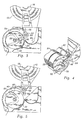
- Fig. 3 discloses the cutter blade 40 in its first condition. Counter clockwise rotation of the toweling support roller 22 to the position shown in Fig. 5 causes partial pivotal movement of the cutter blade to the second condition wherein the cutter blade projects outwardly from the external surface and is disposed at an acute angle with respect thereto, projecting outwardly in a direction generally opposed to the direction of rotation of the toweling support roller.
- the operation of the cutter blade and roller is as disclosed in U.S. Patent No. 6,314,850 . That is to say, action of the cutter blade during rotation of the toweling support roller will sever the toweling to create a toweling sheet severed from the remainder of the paper toweling due to the manual pulling force and tensioning of the toweling between the cutting edge of the cutter blade and the location on the toweling where the pulling force is applied.
- the toweling support roller continues rotation under influence of the associated springs 32, 34 after severing of the toweling to position a lead end of the remainder of the toweling for subsequent manual access and pulling.
- Fig. 6 shows the trailing end of a severed towel sheet 54 and the resulting lead end 56 of the remainder of the toweling.
- Fig. 7 shows the new lead end exiting the bottom opening of the housing which is partially defined by the curved lower end of a closed front cover of the dispenser apparatus upon further rotation of the toweling support roller.
- the paper towel dispenser apparatus differs from the paper towel dispenser of U.S. Patent No. 6,314,850 in a number of respects, one of which is the incorporation with the structure just defined of damping structure including a damping element engaging a portion of a toweling between the roll of paper toweling 12 and the toweling support roller 22 to dampen forces applied to the roll of paper toweling resulting from taking up of toweling slack between the roll of paper toweling and the toweling support roller caused by manual pulling of the remainder of the toweling at a location externally of the housing and resultant overspin of the roll of paper toweling caused thereby.
- Fig. 3 shows a slack portion 60 which exists due to prior dispensing of a severed towel sheet. It has been found that tabbing occurs when overspin slack such as that shown in Fig. 3 is taken up and/or when the blade tries to cut the paper. A "shock" is present at the moment the overspin slack is exhausted.
- the damping structure includes a damping element in the form of a rotatable damping roller 62 which is displaceably mounted relative to the housing.
- stub axles 64 project from the ends of the damping roller, the stub axles being positioned in generally upwardly extending, curved slots 66 formed in housing 10.
- tension springs 67 extending between the stub axles and the housing continuously urge the damping roller downwardly and into engagement with the toweling support roller to form a nip therewith.
- Another aspect of the present invention addressing the tabbing problem which results in the reduction of peak pull force during operation involves modifications relating to blade operation timing. With such modifications the cut is started earlier than in the arrangement shown in U.S. Patent No. 6,314,850 and the cut occurs over a larger amount of drum rotation. With the arrangement disclosed, the rotatable damping roller 62 forms its nip with the toweling support roller at a predetermined location enabling the toweling support roller to rotate at least about 180 degrees from passage of the cutter blade under the rotatable damping roller with the cutter blade in the first condition to a subsequent location wherein the cutter blade is in its third condition.
- the toweling support roller rotates 190 degrees from passage of the cutter blade under the rotatable damping roller with the cutter blade in the first condition A to the location wherein the cutter blade is in the third condition C.
- the nip between the rotatable damping roller and the toweling support roller is located at the rear upper quadrant of the toweling support roller and the axis of rotation of the rotatable damping roller is disposed in a plane passing through the axis of rotation of the toweling support roller forming an angle of 55 degrees with a vertical plane.
- the channel 50 of the cam 52 has been modified from the arrangement shown in U.S. Patent No. 6,314,850 to accomplish the desired end result.
- Fig. 8 shows a second embodiment of the invention which conforms in essentially all respects to the first embodiment just discussed except that a roller 68 is positioned between roll of toweling 12 and damping roller 62 to create additional towel wrap around the damping roller, creating a geometrical condition that gives additional damping action.
Landscapes
- Health & Medical Sciences (AREA)
- Public Health (AREA)
- Life Sciences & Earth Sciences (AREA)
- Forests & Forestry (AREA)
- Engineering & Computer Science (AREA)
- Mechanical Engineering (AREA)
- Unwinding Webs (AREA)
- Replacement Of Web Rolls (AREA)
Claims (6)
- Appareil distributeur d'essuie-tout pour distribuer du papier essuie-tout d'un rouleau (12) de papier essuie-tout en réponse à une force de traction appliquée audit essuie-tout,
comprenant :un logement (10) ;un support de rouleau (14, 16, 18) associé en fonctionnement audit logement (10) pour supporter de manière rotative le rouleau (12) de papier essuie-tout ;un rouleau de support d'essuie-tout rotatif (22) dans ledit logement (10) espacé dudit support de rouleau (14, 16, 18) pour recevoir l'essuie-tout du rouleau (12) de papier essuie-tout et supporter l'essuie-tout, ledit rouleau de support d'essuie-tout (22) présentant une partie périphérique extérieure cylindrique avec une surface externe (24) et étant rotative dans une direction prédéterminée de rotation lorsqu'une force de traction manuelle est appliquée à l'essuie-tout supporté par ici-même ;une lame de coupe (40) située sur la partie périphérique extérieure cylindrique et présentant une arête de coupe (42), ladite lame de coupe (40) étant mobile et pivotable entre une première condition, dans lequel ladite lame de coupe (40) ne fait sensiblement pas saillie vers l'extérieur de la surface externe (24) de ladite partie périphérique extérieure cylindrique et une deuxième condition, dans lequel ladite lame de coupe (40) fait saillie vers l'extérieur de la surface externe (24) de ladite partie périphérique extérieure cylindrique avec l'arête de coupe (42) de celle-ci espacée de la surface externe (24) de ladite partie périphérique extérieure cylindrique ;ladite lame de coupe (40) pivotant autour d'un pivot situé sur ladite surface externe (24) ;des moyens actionneurs de lame (46, 48) pour pivoter ladite lame de coupe (40) entre lesdites première et deuxième conditions en réponse à la rotation dudit rouleau de support d'essuie-tout (22) due à la force de traction manuelle appliquée audit essuie-tout à un endroit externe dudit logement (10) et à la mise sous tension dudit essuie-tout, l'arête de coupe (42) de la lame de coupe (40) lorsque ladite lame de coupe (40) est dans ladite deuxième condition engageant l'essuie-tout sur le rouleau de support d'essuie-tout (22) pendant la rotation du rouleau de support d'essuie-tout (22) pour couper l'essuie-tout pour créer une feuille d'essuie-tout coupée du reste dudit papier essuie-tout dû à ladite force de traction manuelle et à la mise sous tension dudit essuie-tout entre l'arête de coupe de la lame de coupe (40) et l'endroit sur ledit essuie-tout où la force de traction est appliquée, et ledit rouleau de support d'essuie-tout (22) étant rotatif après coupage dudit essuie-tout pour positionner une extrémité avant (56) du reste dudit essuie-tout pour la traction manuelle ultérieure ;caractérisé par
une structure d'amortissement incluant un élément d'amortissement (62) engageant une partie dudit essuie-tout entre ledit rouleau (12) de papier essuie-tout et ledit rouleau de support d'essuie-tout (22) pour amortir des forces appliquées audit rouleau (12) de papier essuie-tout résultant de la prise d'essuie-tout détendu entre ledit rouleau (12) de papier essuie-tout et ledit rouleau de support d'essuie-tout (22) causée par la traction manuelle du reste dudit essuie-tout à un endroit externe dudit logement (10) ;
ledit élément d'amortissement comprenant un rouleau d'amortissement rotatif (62) monté de manière déplaçable par rapport audit logement (10), ledit rouleau (12) de papier essuie-tout et ledit rouleau de support d'essuie-tout (22), ledit rouleau d'amortissement rotatif (62) déplaçable par ladite partie d'essuie-tout s'étendant entre ledit rouleau (12) de papier essuie-tout et ledit rouleau de support d'essuie-tout (22) pour se déplacer dans une direction généralement vers le haut dudit rouleau de support d'essuie-tout (22) lorsque le reste dudit essuie-tout est manuellement tiré et la partie d'essuie-tout s'étendant entre ledit rouleau (12) de papier essuie-tout et ledit rouleau de support d'essuie-tout (22) passe d'une condition détendue à une condition tendue ;
ladite lame de coupe (40) étant sensiblement plate contre le rouleau de support d'essuie-tout (22) avec l'arête de coupe (42) de celle-ci positionnée de manière étroitement adjacente à la surface externe (24) de ladite partie périphérique extérieure cylindrique lorsqu'elle est dans ladite première condition et ladite lame de coupe (40) lorsqu'elle est dans ladite deuxième condition faisant saillie vers l'extérieur depuis la surface externe (24) et agencée selon un angle aigu par rapport à celle-ci, et faisant saillie vers l'extérieur dans une direction généralement en regard de la direction de rotation dudit rouleau de support d'essuie-tout (22) ;
ledit rouleau d'amortissement rotatif (62) étant incliné vers ledit rouleau de support d'essuie-tout (22) pour former alternativement un point de contact avec lui exerçant des forces opposées sur le reste dudit essuie-tout ou déplaçable par la partie d'essuie-tout s'étendant entre ledit rouleau (12) de papier essuie-tout et ledit rouleau de support d'essuie-tout (22) lorsque le reste dudit essuie-tout est manuellement tiré et la partie d'essuie-tout entre ledit rouleau (12) de papier essuie-tout et ledit rouleau de support d'essuie-tout (22) passe d'une condition détendue à une condition tendue ; et
ladite lame de coupe (40) pendant la rotation dudit rouleau de support d'essuie-tout (22) étant mobile de ladite première condition en passant par ladite deuxième condition à une troisième condition, dans lequel ladite lame de coupe (40) est agencée généralement orthogonalement à ladite surface externe (24), ledit rouleau d'amortissement rotatif (62) formant ledit point de contact avec ledit rouleau de support d'essuie-tout (22) à un endroit prédéterminé permettant audit rouleau de support d'essuie-tout (22) de tourner au moins d'environ 180 degrés depuis le passage de ladite lame de coupe (40) sous ledit rouleau d'amortissement rotatif (62) avec ladite lame de coupe (40) dans ladite première condition vers un endroit ultérieur, dans lequel ladite lame de coupe (40) est dans ladite troisième condition. - Appareil distributeur d'essuie-tout selon la revendication 1, dans lequel ledit rouleau d'amortissement rotatif (62) forme ledit point de contact avec ledit rouleau de support d'essuie-tout (22), ledit point de contact étant situé sur le quadrant supérieur arrière dudit rouleau de support d'essuie-tout (22).
- Appareil distributeur d'essuie-tout selon la revendication 1 ou 2, dans lequel ladite structure d'amortissement comprend en outre une structure d'inclinaison associée en fonctionnement audit rouleau d'amortissement rotatif (62) pour incliner ledit rouleau d'amortissement rotatif (62) vers l'essuie-tout s'étendant entre ledit rouleau (12) du papier essuie-tout et ledit rouleau de support d'essuie-tout (22).
- Appareil distributeur d'essuie-tout selon la revendication 3, dans lequel ladite structure d'inclinaison comprend au moins un ressort (67) relié en fonctionnement audit rouleau d'amortissement rotatif (62).
- Appareil distributeur d'essuie-tout selon la revendication 4, dans lequel ladite structure d'amortissement comporte en outre une structure de montage de rouleau d'amortissement dans ledit logement (10) recevant des extrémités en regard dudit rouleau d'amortissement rotatif (62).
- Appareil distributeur d'essuie-tout selon la revendication 5, dans lequel ladite structure de montage de rouleau d'amortissement définit des fentes (66) recevant des extrémités en regard dudit rouleau d'amortissement rotatif (62) et guidant le mouvement desdites extrémités en regard lorsque l'essuie-tout s'étendant entre ledit rouleau (12) de papier essuie-tout et ledit rouleau de support d'essuie-tout (22) change entre la condition détendue et la condition tendue.
Applications Claiming Priority (2)
| Application Number | Priority Date | Filing Date | Title |
|---|---|---|---|
| US11/114,860 US7500420B2 (en) | 2005-04-25 | 2005-04-25 | Paper towel dispenser apparatus |
| PCT/US2006/014796 WO2006115952A2 (fr) | 2005-04-25 | 2006-04-19 | Appareil distributeur d'essuie-tout |
Publications (3)
| Publication Number | Publication Date |
|---|---|
| EP1877230A2 EP1877230A2 (fr) | 2008-01-16 |
| EP1877230A4 EP1877230A4 (fr) | 2013-01-16 |
| EP1877230B1 true EP1877230B1 (fr) | 2016-10-26 |
Family
ID=37185478
Family Applications (1)
| Application Number | Title | Priority Date | Filing Date |
|---|---|---|---|
| EP06750760.8A Expired - Lifetime EP1877230B1 (fr) | 2005-04-25 | 2006-04-19 | Appareil distributeur d'essuie-tout |
Country Status (4)
| Country | Link |
|---|---|
| US (1) | US7500420B2 (fr) |
| EP (1) | EP1877230B1 (fr) |
| CA (1) | CA2605411C (fr) |
| WO (1) | WO2006115952A2 (fr) |
Cited By (1)
| Publication number | Priority date | Publication date | Assignee | Title |
|---|---|---|---|---|
| US11479431B2 (en) | 2019-07-19 | 2022-10-25 | Dispensing Dynamics International, Inc. | Dispensing systems with floating support rollers |
Families Citing this family (35)
| Publication number | Priority date | Publication date | Assignee | Title |
|---|---|---|---|---|
| US7987756B2 (en) * | 2007-12-03 | 2011-08-02 | Kimberly-Clark Worldwide Inc. | Electro-manual dispenser |
| US20100102101A1 (en) * | 2008-10-28 | 2010-04-29 | Perrin Manufacturing Company | Paper toweling dispenser apparatus |
| US8382026B2 (en) * | 2009-05-27 | 2013-02-26 | Dispensing Dynamics International | Multi-function paper toweling dispenser |
| AT508112B1 (de) * | 2009-06-23 | 2010-11-15 | Hagleitner Hans Georg | Messerführung für eine vorrichtung zur ausgabe von papierabschnitten |
| CN103068289A (zh) * | 2010-07-07 | 2013-04-24 | Sca卫生用品公司 | 分配器 |
| EP2760773A4 (fr) | 2011-09-26 | 2015-03-04 | Cascades Canada Ulc | Distributeur de produit enroulé doté de multiples lames de coupe et ensemble de coupe pour distributeur de produit enroulé |
| MX370885B (es) * | 2012-05-08 | 2020-01-09 | Dispensing Dynamics Int Llc | Aparato dispensador de material de hoja de papel. |
| CN202654043U (zh) * | 2012-07-11 | 2013-01-09 | 济南爱德机器有限公司 | 自动切纸机 |
| US20140374434A1 (en) * | 2013-06-19 | 2014-12-25 | David C.T. Jour | Notepaper Dispensing Box |
| US9795258B2 (en) | 2013-09-05 | 2017-10-24 | Dispensing Dynamics International, Llc | Dispenser apparatus with damper for dispensing paper toweling |
| US9730559B2 (en) | 2014-04-10 | 2017-08-15 | Dispensing Dynamics International, Llc | Electro-mechanical paper sheet material dispenser with tail sensor |
| MX383288B (es) | 2014-08-08 | 2025-03-13 | Gpcp Ip Holdings Llc | Dispensadores de producto de hoja y metodos relacionados para reducir el uso del producto de hoja. |
| US9895033B2 (en) | 2014-12-05 | 2018-02-20 | Dispensing Dynamics International, Llc | Dispenser apparatus with damper for dispensing paper toweling |
| US9907442B2 (en) | 2015-02-24 | 2018-03-06 | Dispensing Dynamics International, Llc | Paper toweling or tissue dispensing apparatus including roll overspin control |
| US9854948B1 (en) | 2015-03-31 | 2018-01-02 | Wisconsin Plastics, Inc. | Paper towel dispenser |
| US11109722B2 (en) * | 2015-06-04 | 2021-09-07 | Charles Agnew Osborne, Jr. | Dispenser for rolled sheet materials |
| CA2903189A1 (fr) * | 2015-08-31 | 2017-02-28 | Wal-Mart Stores, Inc. | Distributeur de sac |
| US10271695B2 (en) * | 2015-10-16 | 2019-04-30 | Dispensing Dynamics International, Llc | Paper towel dispenser damping system |
| USD790872S1 (en) | 2015-12-28 | 2017-07-04 | Kimberly-Clark Worldwide, Inc. | Paper product dispenser |
| RU2018128380A (ru) | 2016-01-06 | 2020-02-06 | ЭССИТИ ОПЕРЕЙШНС УОСО ЭлЭлСИ | Выдачное устройство для рулонного материала |
| EP3525643B1 (fr) | 2016-10-13 | 2024-02-28 | Dispensing Dynamics International, LLC | Système d'amortissement pour distributeur de serviettes en papier |
| US10517445B2 (en) | 2016-10-13 | 2019-12-31 | Dispensing Dynamics International, Llc | Roll paper towel or tissue dispenser with spring dampening roll support |
| US12358750B2 (en) | 2016-12-20 | 2025-07-15 | Charles Agnew Osborne, Jr. | Cutting system for a dispenser |
| US10850938B2 (en) | 2017-10-09 | 2020-12-01 | Gpcp Ip Holdings Llc | Mechanical sheet product dispenser |
| US10362909B2 (en) * | 2017-11-20 | 2019-07-30 | Guangzhou Faner Aroma Product Co., Ltd. | Paper dispensing device |
| CA3036158C (fr) | 2018-03-09 | 2026-03-03 | Cascades Canada Ulc | Distributeur de rouleau de materiau en bande et mecanisme de support de rouleau destine a un distributeur de rouleau de materiau en bande |
| US11154166B2 (en) | 2018-05-24 | 2021-10-26 | Charles Agnew Osborne, Jr. | Dispenser for rolled sheet materials |
| US12268341B2 (en) | 2018-05-24 | 2025-04-08 | Charles Agnew Osborne, Jr. | Sheet material dispensing assembly with integrated gear clutch |
| CA3101354C (fr) | 2018-05-24 | 2023-10-03 | Charles Agnew Osborne, Jr. | Distributeur pour materiaux en feuille roules |
| WO2020025837A1 (fr) * | 2018-08-03 | 2020-02-06 | Jofel Industrial, S.A. | Distributeur de papier à mécanisme d'auto-découpe |
| WO2020123491A1 (fr) | 2018-12-12 | 2020-06-18 | Osborne Charles Agnew Jr | Ensemble de distribution destiné à distribuer sélectivement une pluralité de réserves de matériau en feuille roulé |
| BR112021022484A2 (pt) * | 2019-07-05 | 2022-01-25 | Essity Hygiene & Health Ab | Dispensador e método de carregamento de um dispensador |
| US12507839B2 (en) | 2019-11-22 | 2025-12-30 | Gpcp Ip Holdings Llc | Frictional features for rolled sheet product dispensers |
| US12329327B2 (en) | 2022-02-08 | 2025-06-17 | Vsi Health And Hygiene Group, Llc | Sheet material dispenser assembly for selectively dispensing sheet material from a plurality of supplies of rolled sheet material |
| CN115379934B (zh) * | 2022-04-26 | 2023-06-20 | 广州凡而芳香日用品有限公司 | 一种切割辊及纸张分配器 |
Family Cites Families (32)
| Publication number | Priority date | Publication date | Assignee | Title |
|---|---|---|---|---|
| US1543299A (en) | 1922-07-21 | 1925-06-23 | Economy Paper Company | Paper-towel-vending machine |
| US2051242A (en) | 1935-04-08 | 1936-08-18 | Steiner Sales Co | Paper towel dispensing apparatus |
| US2560061A (en) | 1946-03-06 | 1951-07-10 | Fort Howard Paper Co | Paper dispenser |
| US3575328A (en) | 1969-01-24 | 1971-04-20 | Georgia Pacific Corp | Dispenser for flexible sheet material and a perforating mechanism adapted to be used therein |
| US3739965A (en) | 1969-01-24 | 1973-06-19 | Georgia Pacific Corp | Dispenser for flexible sheet material and a perforating mechanism adapted to be used therein |
| USRE28911E (en) | 1971-01-06 | 1976-07-20 | Georgia-Pacific Corporation | Dispenser for flexible sheet material and a perforating mechanism adapted to be used therein |
| OA04528A (fr) | 1972-04-27 | 1980-03-30 | Granger Maurice | Dispositif de distribution et coupe simultannées de bandes de matériaux enroulés. |
| US3998120A (en) | 1974-04-05 | 1976-12-21 | Sebas S.A. Societe D'exploitation D'appareils Sanitaires | Apparatus for the simultaneous distribution and cutting of strips of rolled materials |
| US4213363A (en) | 1975-11-19 | 1980-07-22 | Maurice Granger | Apparatus for the cutting and simultaneous dispensing of a web of roll material |
| FR2332215A1 (fr) | 1975-11-19 | 1977-06-17 | Granger Maurice | Appareil de coupe et de distribution simultanees de bandes de materiaux enroules |
| US4188363A (en) * | 1976-08-19 | 1980-02-12 | Bayer Aktiengesellschaft | Recovery of rhodium complex catalysts homogeneously dissolved in organic media |
| CH615817A5 (fr) | 1977-04-19 | 1980-02-29 | Apura Gmbh | |
| US4404880A (en) * | 1977-10-14 | 1983-09-20 | Georgia-Pacific Corporation | Method for web cutting in rolled sheet material dispensers |
| US4188844A (en) | 1977-10-14 | 1980-02-19 | Georgia-Pacific Corporation | Dispenser for rolls of flexible sheet material and cutter mechanism for use therein |
| US4307639A (en) | 1978-04-18 | 1981-12-29 | Georgia-Pacific Corporation | Multiple wound roll dispenser for flexible sheet material |
| US4441392A (en) | 1981-11-04 | 1984-04-10 | Georgia-Pacific Corporation | Cut web material dispenser with web centering and tension control |
| US4432261A (en) | 1981-12-23 | 1984-02-21 | Georgia-Pacific Corporation | Severing web plies in multiple roll material dispensers |
| FR2555975B1 (fr) | 1983-12-06 | 1986-11-21 | Granger Maurice | Appareil de distribution et de coupe simultanee de bandes de materiaux enroules, avec au moins un rouleau de materiau en service |
| FR2561633B1 (fr) | 1984-03-21 | 1986-08-22 | Granger Maurice | Appareil de distribution et de coupe simultanees de bandes de materiaux enroules |
| US4712461A (en) * | 1985-10-18 | 1987-12-15 | Georgia-Pacific Corporation | Rolled material dispenser with feed roller containing a sliding cutter |
| FR2599726B1 (fr) | 1986-06-09 | 1989-04-21 | Granger Maurice | Appareil distributeur de longueurs de materiaux enroules sur un noyau, avec dispositif de remplacement automatique du rouleau en service, par un rouleau de reserve |
| FR2609010B1 (fr) | 1986-12-30 | 1990-04-27 | Granger Maurice | Dispositif de coupe perfectionne pour un appareil de distribution et de coupe simultanees de bandes de materiaux enroules |
| FR2632292B2 (fr) | 1988-04-26 | 1991-10-04 | Granger Maurice | |
| US4807824A (en) | 1988-06-27 | 1989-02-28 | James River Ii, Inc. | Paper roll towel dispenser |
| US5207633A (en) * | 1989-03-03 | 1993-05-04 | Maurice Granger | Apparatus to dispense discrete portions of corrugated wiping materials |
| FR2643807B1 (fr) | 1989-03-03 | 1991-07-12 | Granger Maurice | Dispositif de coupe de materiaux d'essuyage stockes dans un appareil assurant leur distribution automatique sous la forme d'une bande etroite pliee en accordeon |
| FR2647048B1 (fr) | 1989-05-16 | 1991-08-30 | Granger Maurice | Dispositif de coupe de materiaux d'essuyage stockes dans un appareil assurant leur distribution automatique sous la forme d'une bande etroite pliee en accordeon |
| US5048386A (en) * | 1989-10-27 | 1991-09-17 | Georgia-Pacific Corporation | Feed mechanism for flexible sheet material dispensers |
| FR2656601B1 (fr) | 1989-12-28 | 1992-04-24 | Maurice Granger | Appareil de distribution et de coupe simultanees de bandes de materiaux enroules. |
| US5078033A (en) | 1990-11-13 | 1992-01-07 | Georgia-Pacific Corporation | Flexible sheet material dispenser |
| US6314850B1 (en) * | 1998-01-22 | 2001-11-13 | Perrin Manufacturing Company | Paper toweling dispensing system |
| US5979822A (en) * | 1998-09-30 | 1999-11-09 | Perrin Manufacturing Company | Apparatus for dispensing sheet material from a roll of sheet material |
-
2005
- 2005-04-25 US US11/114,860 patent/US7500420B2/en active Active
-
2006
- 2006-04-19 EP EP06750760.8A patent/EP1877230B1/fr not_active Expired - Lifetime
- 2006-04-19 CA CA2605411A patent/CA2605411C/fr not_active Expired - Lifetime
- 2006-04-19 WO PCT/US2006/014796 patent/WO2006115952A2/fr not_active Ceased
Non-Patent Citations (1)
| Title |
|---|
| None * |
Cited By (1)
| Publication number | Priority date | Publication date | Assignee | Title |
|---|---|---|---|---|
| US11479431B2 (en) | 2019-07-19 | 2022-10-25 | Dispensing Dynamics International, Inc. | Dispensing systems with floating support rollers |
Also Published As
| Publication number | Publication date |
|---|---|
| EP1877230A4 (fr) | 2013-01-16 |
| US20060236832A1 (en) | 2006-10-26 |
| US7500420B2 (en) | 2009-03-10 |
| WO2006115952A3 (fr) | 2007-09-13 |
| CA2605411C (fr) | 2013-06-25 |
| WO2006115952A2 (fr) | 2006-11-02 |
| CA2605411A1 (fr) | 2006-11-02 |
| EP1877230A2 (fr) | 2008-01-16 |
Similar Documents
| Publication | Publication Date | Title |
|---|---|---|
| EP1877230B1 (fr) | Appareil distributeur d'essuie-tout | |
| KR100342791B1 (ko) | 두루마리 웨브 분배기 및 절단장치 | |
| US6553879B2 (en) | Paper toweling dispensing system | |
| CA2205152C (fr) | Systeme de distribution d'un materiau en feuille | |
| AU2002245729B2 (en) | Easy loading dispenser | |
| US4846412A (en) | Two roll sheet material dispenser | |
| EP0573558B1 (fr) | Procede et appareil pour distribuer un materiau en feuille souple | |
| US5400982A (en) | Dispenser for multiple rolls of sheet material | |
| EP3226735B1 (fr) | Appareil distributeur avec amortisseur pour la distribution papier essuie-mains | |
| WO2010062327A1 (fr) | Appareil de distribution de papier essuie-tout | |
| WO2016032627A1 (fr) | Appareil distributeur avec amortisseur pour distribution de papier essuie-tout | |
| US20180325331A1 (en) | Device for separating paper sections from a paper web wound onto a paper roll, as well as a knife for separating the paper sections | |
| US20180325330A1 (en) | Device for dispensing paper sections of predetermined length | |
| EP0693268A1 (fr) | Dispositif pour découpage et distribution de serviettes individuelles en papier | |
| EP1412143B1 (fr) | Systeme de distribution de papier serviette | |
| EP3525643B1 (fr) | Système d'amortissement pour distributeur de serviettes en papier | |
| JP3571683B2 (ja) | ロール紙巻取切断機 | |
| EP3694383B1 (fr) | Distributeur de serviettes ou de mouchoirs en papier à rouleaux avec support de rouleau à amortisseur à ressort | |
| NZ742164A (en) | A device for separating paper sections from a paper web wound onto a paper roll, as well as a knife for separating the paper sections. | |
| NZ742173A (en) | Device for dispensing paper sections of predetermined length |
Legal Events
| Date | Code | Title | Description |
|---|---|---|---|
| PUAI | Public reference made under article 153(3) epc to a published international application that has entered the european phase |
Free format text: ORIGINAL CODE: 0009012 |
|
| 17P | Request for examination filed |
Effective date: 20071120 |
|
| AK | Designated contracting states |
Kind code of ref document: A2 Designated state(s): AT BE BG CH CY CZ DE DK EE ES FI FR GB GR HU IE IS IT LI LT LU LV MC NL PL PT RO SE SI SK TR |
|
| AX | Request for extension of the european patent |
Extension state: AL BA HR MK YU |
|
| DAX | Request for extension of the european patent (deleted) | ||
| RAP1 | Party data changed (applicant data changed or rights of an application transferred) |
Owner name: DISPENSING DYNAMICS INTERNATIONAL |
|
| A4 | Supplementary search report drawn up and despatched |
Effective date: 20121213 |
|
| RIC1 | Information provided on ipc code assigned before grant |
Ipc: A47K 10/38 20060101ALI20121207BHEP Ipc: B26D 1/62 20060101AFI20121207BHEP |
|
| 17Q | First examination report despatched |
Effective date: 20150708 |
|
| GRAP | Despatch of communication of intention to grant a patent |
Free format text: ORIGINAL CODE: EPIDOSNIGR1 |
|
| RIC1 | Information provided on ipc code assigned before grant |
Ipc: B26D 1/62 20060101AFI20160428BHEP Ipc: B26F 3/02 20060101ALI20160428BHEP Ipc: A47K 10/38 20060101ALI20160428BHEP |
|
| INTG | Intention to grant announced |
Effective date: 20160602 |
|
| GRAS | Grant fee paid |
Free format text: ORIGINAL CODE: EPIDOSNIGR3 |
|
| GRAA | (expected) grant |
Free format text: ORIGINAL CODE: 0009210 |
|
| AK | Designated contracting states |
Kind code of ref document: B1 Designated state(s): AT BE BG CH CY CZ DE DK EE ES FI FR GB GR HU IE IS IT LI LT LU LV MC NL PL PT RO SE SI SK TR |
|
| REG | Reference to a national code |
Ref country code: GB Ref legal event code: FG4D |
|
| REG | Reference to a national code |
Ref country code: CH Ref legal event code: EP |
|
| REG | Reference to a national code |
Ref country code: AT Ref legal event code: REF Ref document number: 839670 Country of ref document: AT Kind code of ref document: T Effective date: 20161115 |
|
| REG | Reference to a national code |
Ref country code: IE Ref legal event code: FG4D |
|
| REG | Reference to a national code |
Ref country code: DE Ref legal event code: R096 Ref document number: 602006050701 Country of ref document: DE |
|
| REG | Reference to a national code |
Ref country code: LT Ref legal event code: MG4D |
|
| PG25 | Lapsed in a contracting state [announced via postgrant information from national office to epo] |
Ref country code: LV Free format text: LAPSE BECAUSE OF FAILURE TO SUBMIT A TRANSLATION OF THE DESCRIPTION OR TO PAY THE FEE WITHIN THE PRESCRIBED TIME-LIMIT Effective date: 20161026 |
|
| REG | Reference to a national code |
Ref country code: NL Ref legal event code: MP Effective date: 20161026 |
|
| REG | Reference to a national code |
Ref country code: AT Ref legal event code: MK05 Ref document number: 839670 Country of ref document: AT Kind code of ref document: T Effective date: 20161026 |
|
| REG | Reference to a national code |
Ref country code: FR Ref legal event code: PLFP Year of fee payment: 12 |
|
| PG25 | Lapsed in a contracting state [announced via postgrant information from national office to epo] |
Ref country code: LT Free format text: LAPSE BECAUSE OF FAILURE TO SUBMIT A TRANSLATION OF THE DESCRIPTION OR TO PAY THE FEE WITHIN THE PRESCRIBED TIME-LIMIT Effective date: 20161026 Ref country code: GR Free format text: LAPSE BECAUSE OF FAILURE TO SUBMIT A TRANSLATION OF THE DESCRIPTION OR TO PAY THE FEE WITHIN THE PRESCRIBED TIME-LIMIT Effective date: 20170127 Ref country code: SE Free format text: LAPSE BECAUSE OF FAILURE TO SUBMIT A TRANSLATION OF THE DESCRIPTION OR TO PAY THE FEE WITHIN THE PRESCRIBED TIME-LIMIT Effective date: 20161026 |
|
| PG25 | Lapsed in a contracting state [announced via postgrant information from national office to epo] |
Ref country code: NL Free format text: LAPSE BECAUSE OF FAILURE TO SUBMIT A TRANSLATION OF THE DESCRIPTION OR TO PAY THE FEE WITHIN THE PRESCRIBED TIME-LIMIT Effective date: 20161026 Ref country code: BE Free format text: LAPSE BECAUSE OF FAILURE TO SUBMIT A TRANSLATION OF THE DESCRIPTION OR TO PAY THE FEE WITHIN THE PRESCRIBED TIME-LIMIT Effective date: 20161026 Ref country code: AT Free format text: LAPSE BECAUSE OF FAILURE TO SUBMIT A TRANSLATION OF THE DESCRIPTION OR TO PAY THE FEE WITHIN THE PRESCRIBED TIME-LIMIT Effective date: 20161026 Ref country code: PL Free format text: LAPSE BECAUSE OF FAILURE TO SUBMIT A TRANSLATION OF THE DESCRIPTION OR TO PAY THE FEE WITHIN THE PRESCRIBED TIME-LIMIT Effective date: 20161026 Ref country code: ES Free format text: LAPSE BECAUSE OF FAILURE TO SUBMIT A TRANSLATION OF THE DESCRIPTION OR TO PAY THE FEE WITHIN THE PRESCRIBED TIME-LIMIT Effective date: 20161026 Ref country code: PT Free format text: LAPSE BECAUSE OF FAILURE TO SUBMIT A TRANSLATION OF THE DESCRIPTION OR TO PAY THE FEE WITHIN THE PRESCRIBED TIME-LIMIT Effective date: 20170227 Ref country code: FI Free format text: LAPSE BECAUSE OF FAILURE TO SUBMIT A TRANSLATION OF THE DESCRIPTION OR TO PAY THE FEE WITHIN THE PRESCRIBED TIME-LIMIT Effective date: 20161026 Ref country code: IS Free format text: LAPSE BECAUSE OF FAILURE TO SUBMIT A TRANSLATION OF THE DESCRIPTION OR TO PAY THE FEE WITHIN THE PRESCRIBED TIME-LIMIT Effective date: 20170226 |
|
| REG | Reference to a national code |
Ref country code: DE Ref legal event code: R082 Ref document number: 602006050701 Country of ref document: DE Representative=s name: PATENTANWAELTE EINSEL & KOLLEGEN, DE Ref country code: DE Ref legal event code: R081 Ref document number: 602006050701 Country of ref document: DE Owner name: DISPENSING DYNAMICS INTERNATIONAL, LLC, CITY O, US Free format text: FORMER OWNER: DISPENSING DYNAMICS INTERNATIONAL, CITY OF INDUSTRY, CALIF., US |
|
| REG | Reference to a national code |
Ref country code: DE Ref legal event code: R097 Ref document number: 602006050701 Country of ref document: DE |
|
| PG25 | Lapsed in a contracting state [announced via postgrant information from national office to epo] |
Ref country code: CZ Free format text: LAPSE BECAUSE OF FAILURE TO SUBMIT A TRANSLATION OF THE DESCRIPTION OR TO PAY THE FEE WITHIN THE PRESCRIBED TIME-LIMIT Effective date: 20161026 Ref country code: SK Free format text: LAPSE BECAUSE OF FAILURE TO SUBMIT A TRANSLATION OF THE DESCRIPTION OR TO PAY THE FEE WITHIN THE PRESCRIBED TIME-LIMIT Effective date: 20161026 Ref country code: RO Free format text: LAPSE BECAUSE OF FAILURE TO SUBMIT A TRANSLATION OF THE DESCRIPTION OR TO PAY THE FEE WITHIN THE PRESCRIBED TIME-LIMIT Effective date: 20161026 Ref country code: EE Free format text: LAPSE BECAUSE OF FAILURE TO SUBMIT A TRANSLATION OF THE DESCRIPTION OR TO PAY THE FEE WITHIN THE PRESCRIBED TIME-LIMIT Effective date: 20161026 Ref country code: DK Free format text: LAPSE BECAUSE OF FAILURE TO SUBMIT A TRANSLATION OF THE DESCRIPTION OR TO PAY THE FEE WITHIN THE PRESCRIBED TIME-LIMIT Effective date: 20161026 |
|
| REG | Reference to a national code |
Ref country code: FR Ref legal event code: CD Owner name: DISPENSING DYNAMICS INTERNATIONAL, LLC, US Effective date: 20170703 |
|
| PG25 | Lapsed in a contracting state [announced via postgrant information from national office to epo] |
Ref country code: BG Free format text: LAPSE BECAUSE OF FAILURE TO SUBMIT A TRANSLATION OF THE DESCRIPTION OR TO PAY THE FEE WITHIN THE PRESCRIBED TIME-LIMIT Effective date: 20170126 |
|
| PLBE | No opposition filed within time limit |
Free format text: ORIGINAL CODE: 0009261 |
|
| STAA | Information on the status of an ep patent application or granted ep patent |
Free format text: STATUS: NO OPPOSITION FILED WITHIN TIME LIMIT |
|
| 26N | No opposition filed |
Effective date: 20170727 |
|
| PG25 | Lapsed in a contracting state [announced via postgrant information from national office to epo] |
Ref country code: SI Free format text: LAPSE BECAUSE OF FAILURE TO SUBMIT A TRANSLATION OF THE DESCRIPTION OR TO PAY THE FEE WITHIN THE PRESCRIBED TIME-LIMIT Effective date: 20161026 |
|
| REG | Reference to a national code |
Ref country code: CH Ref legal event code: PL |
|
| REG | Reference to a national code |
Ref country code: IE Ref legal event code: MM4A |
|
| PG25 | Lapsed in a contracting state [announced via postgrant information from national office to epo] |
Ref country code: MC Free format text: LAPSE BECAUSE OF FAILURE TO SUBMIT A TRANSLATION OF THE DESCRIPTION OR TO PAY THE FEE WITHIN THE PRESCRIBED TIME-LIMIT Effective date: 20161026 |
|
| PG25 | Lapsed in a contracting state [announced via postgrant information from national office to epo] |
Ref country code: CH Free format text: LAPSE BECAUSE OF NON-PAYMENT OF DUE FEES Effective date: 20170430 Ref country code: LU Free format text: LAPSE BECAUSE OF NON-PAYMENT OF DUE FEES Effective date: 20170419 Ref country code: LI Free format text: LAPSE BECAUSE OF NON-PAYMENT OF DUE FEES Effective date: 20170430 |
|
| REG | Reference to a national code |
Ref country code: FR Ref legal event code: PLFP Year of fee payment: 13 |
|
| PG25 | Lapsed in a contracting state [announced via postgrant information from national office to epo] |
Ref country code: IE Free format text: LAPSE BECAUSE OF NON-PAYMENT OF DUE FEES Effective date: 20170419 |
|
| PG25 | Lapsed in a contracting state [announced via postgrant information from national office to epo] |
Ref country code: HU Free format text: LAPSE BECAUSE OF FAILURE TO SUBMIT A TRANSLATION OF THE DESCRIPTION OR TO PAY THE FEE WITHIN THE PRESCRIBED TIME-LIMIT; INVALID AB INITIO Effective date: 20060419 |
|
| PG25 | Lapsed in a contracting state [announced via postgrant information from national office to epo] |
Ref country code: CY Free format text: LAPSE BECAUSE OF NON-PAYMENT OF DUE FEES Effective date: 20161026 |
|
| PG25 | Lapsed in a contracting state [announced via postgrant information from national office to epo] |
Ref country code: TR Free format text: LAPSE BECAUSE OF FAILURE TO SUBMIT A TRANSLATION OF THE DESCRIPTION OR TO PAY THE FEE WITHIN THE PRESCRIBED TIME-LIMIT Effective date: 20161026 |
|
| PGFP | Annual fee paid to national office [announced via postgrant information from national office to epo] |
Ref country code: FR Payment date: 20230309 Year of fee payment: 18 |
|
| PGFP | Annual fee paid to national office [announced via postgrant information from national office to epo] |
Ref country code: IT Payment date: 20230310 Year of fee payment: 18 Ref country code: GB Payment date: 20230302 Year of fee payment: 18 |
|
| PGFP | Annual fee paid to national office [announced via postgrant information from national office to epo] |
Ref country code: DE Payment date: 20230307 Year of fee payment: 18 |
|
| REG | Reference to a national code |
Ref country code: DE Ref legal event code: R119 Ref document number: 602006050701 Country of ref document: DE |
|
| GBPC | Gb: european patent ceased through non-payment of renewal fee |
Effective date: 20240419 |
|
| PG25 | Lapsed in a contracting state [announced via postgrant information from national office to epo] |
Ref country code: DE Free format text: LAPSE BECAUSE OF NON-PAYMENT OF DUE FEES Effective date: 20241105 |
|
| PG25 | Lapsed in a contracting state [announced via postgrant information from national office to epo] |
Ref country code: GB Free format text: LAPSE BECAUSE OF NON-PAYMENT OF DUE FEES Effective date: 20240419 |
|
| PG25 | Lapsed in a contracting state [announced via postgrant information from national office to epo] |
Ref country code: FR Free format text: LAPSE BECAUSE OF NON-PAYMENT OF DUE FEES Effective date: 20240430 |
|
| PG25 | Lapsed in a contracting state [announced via postgrant information from national office to epo] |
Ref country code: GB Free format text: LAPSE BECAUSE OF NON-PAYMENT OF DUE FEES Effective date: 20240419 Ref country code: FR Free format text: LAPSE BECAUSE OF NON-PAYMENT OF DUE FEES Effective date: 20240430 Ref country code: DE Free format text: LAPSE BECAUSE OF NON-PAYMENT OF DUE FEES Effective date: 20241105 |
|
| PG25 | Lapsed in a contracting state [announced via postgrant information from national office to epo] |
Ref country code: IT Free format text: LAPSE BECAUSE OF NON-PAYMENT OF DUE FEES Effective date: 20240419 |