EP1878366A2 - Récipient, en particulier saladier pour cuisson, présentation, garde et/ou service et couvercle pour un tel récipient - Google Patents
Récipient, en particulier saladier pour cuisson, présentation, garde et/ou service et couvercle pour un tel récipient Download PDFInfo
- Publication number
- EP1878366A2 EP1878366A2 EP07010295A EP07010295A EP1878366A2 EP 1878366 A2 EP1878366 A2 EP 1878366A2 EP 07010295 A EP07010295 A EP 07010295A EP 07010295 A EP07010295 A EP 07010295A EP 1878366 A2 EP1878366 A2 EP 1878366A2
- Authority
- EP
- European Patent Office
- Prior art keywords
- vessel
- zone
- lid
- closing element
- ventilation
- Prior art date
- Legal status (The legal status is an assumption and is not a legal conclusion. Google has not performed a legal analysis and makes no representation as to the accuracy of the status listed.)
- Withdrawn
Links
Images
Classifications
-
- A—HUMAN NECESSITIES
- A47—FURNITURE; DOMESTIC ARTICLES OR APPLIANCES; COFFEE MILLS; SPICE MILLS; SUCTION CLEANERS IN GENERAL
- A47G—HOUSEHOLD OR TABLE EQUIPMENT
- A47G19/00—Table service
- A47G19/02—Plates, dishes or the like
-
- A—HUMAN NECESSITIES
- A47—FURNITURE; DOMESTIC ARTICLES OR APPLIANCES; COFFEE MILLS; SPICE MILLS; SUCTION CLEANERS IN GENERAL
- A47J—KITCHEN EQUIPMENT; COFFEE MILLS; SPICE MILLS; APPARATUS FOR MAKING BEVERAGES
- A47J36/00—Parts, details or accessories of cooking-vessels
- A47J36/06—Lids or covers for cooking-vessels
-
- A—HUMAN NECESSITIES
- A47—FURNITURE; DOMESTIC ARTICLES OR APPLIANCES; COFFEE MILLS; SPICE MILLS; SUCTION CLEANERS IN GENERAL
- A47J—KITCHEN EQUIPMENT; COFFEE MILLS; SPICE MILLS; APPARATUS FOR MAKING BEVERAGES
- A47J27/00—Cooking-vessels
-
- A—HUMAN NECESSITIES
- A47—FURNITURE; DOMESTIC ARTICLES OR APPLIANCES; COFFEE MILLS; SPICE MILLS; SUCTION CLEANERS IN GENERAL
- A47J—KITCHEN EQUIPMENT; COFFEE MILLS; SPICE MILLS; APPARATUS FOR MAKING BEVERAGES
- A47J36/00—Parts, details or accessories of cooking-vessels
- A47J36/36—Shields or jackets for cooking utensils minimising the radiation of heat, fastened or movably mounted
-
- A—HUMAN NECESSITIES
- A47—FURNITURE; DOMESTIC ARTICLES OR APPLIANCES; COFFEE MILLS; SPICE MILLS; SUCTION CLEANERS IN GENERAL
- A47J—KITCHEN EQUIPMENT; COFFEE MILLS; SPICE MILLS; APPARATUS FOR MAKING BEVERAGES
- A47J45/00—Devices for fastening or gripping kitchen utensils or crockery
- A47J45/06—Handles for hollow-ware articles
- A47J45/062—Bowl handles
Definitions
- the invention relates to a vessel, in particular a bowl for cooking, Anricht-, storage and / or Servier inclusivee, with a steep peripheral wall, which merges in the region of the upper edge of the vessel having an outwardly flared zone of less steepness.
- Vessels of this kind are widespread and z. B. as bowls or pots everyday objects in the household.
- Such vessels may consist of different materials or combinations of materials, such as stainless steel, ceramic or plastic.
- the invention has for its object to provide a vessel of the type mentioned, which is well suited as a dispensing dosing for liquid materials of different viscosities, but also as a storage vessel and has an attractive design.
- the size of the outwardly flared zone in particular its radial width considered in plan view from above, varies along the circumference of the vessel.
- the term "outwardly crimped" in the terminology of this application is to be understood as meaning the edge shape of the upper vessel region that transitions from a zone of greater steepness into a zone of less steepness, and it is not absolutely necessary to derive a protection range limitation on the crimping as a shaping method used for the production.
- the outwardly flared zone is produced by a deep-drawing process.
- the outwardly flared zone of varying size in the circumferential direction of the vessel extends over more than half of the circumferential length of the vessel, in particular over the whole Circumferential length of the vessel, wherein the size of the outwardly flared zone, in particular their - viewed in plan view from above - radial width, continuously varies continuously along the circumference of the vessel.
- the outwardly flared zone forms a pouring edge of varying width.
- the vessel can be used depending on the orientation for an optimized, rapid and targeted pouring of materials of different viscosities.
- the edge of the outwardly flared zone is designed to form a tear-off edge for the liquid in question during pouring.
- the vessel preferably has a round, in particular circular base shape below the outwardly flared zone.
- the outwardly flanged zone - viewed in each vertical radial longitudinal section - extends approximately rectilinearly or with at most slight curvature to the outside.
- the steepness or the degree of inclination of the radially outwardly flanged zone may vary in one embodiment and in another embodiment - as viewed in each vertical radial longitudinal section - be substantially the same.
- the vessel and hence the outwardly flared zone, is symmetrical with respect to a vertical center plane of the vessel, with the vertical center plane intersecting the outwardly flared zone, as seen in plan view from above, at their radially widest point and at their radially narrowest point ,
- the radial width of the outwardly flared zone increases continuously from the narrowest point to the widest point along the circumference of the vessel.
- the vessel below the outwardly flanged zone is rotationally symmetric with respect to a central axis, as already indicated above, wherein the outer edge contour of the outwardly flared zone is rotationally symmetric and in plan view describes a circle, the center of which laterally offset relative to the center axis is.
- a design is manufacturing technology and advantageous from a design point of view.
- the outer edge contour of the outwardly flared zone describes an ellipse or an oval.
- the zone which is crimped outwards is large enough at its radially widest point to form a grip section which can be grasped comfortably with the thumb and forefinger or middle finger of one hand, so that the vessel can be gripped with only one Hand can be held securely, such as pouring a liquid or when moving from one place to another place.
- the vessel is made of stainless steel.
- the invention further relates to a lid for a vessel, in particular a lid for a vessel according to one of the claims 1-11, wherein the lid has a cover plate and an adjustable Beflcommunungsventil on the cover plate.
- the ventilation valve has a valve closing element, which is movably guided between a closed position and a maximum opening position in a closing element receptacle, which has at least one perforated ventilation zone, the valve closing element sealing the ventilation zone in its closed position overlaps, and wherein the valve closing element from the closed position is movable with decrease in the degree of overlap in its maximum opening position in which it largely releases the perforated ventilation zone.
- the ventilation valve works reliably and can be produced with simple means.
- the closing element receptacle preferably represents a sliding displacement guide for the valve closing element.
- valve closure member is rotatably supported about a rotation axis in the closing element receiving, wherein it is movable by rotating about the axis of rotation between the closed position and the maximum opening position in a preferably constant plane to vary the degree of overlap between valve closing element and ventilation zone accordingly.
- the closing element receptacle according to a preferred embodiment of the lid according to the invention comprises a recess, in particular embossing in the cover plate, wherein in this recess the valve closing element is received so that it does not project beyond the upper edge of the recess to the outside.
- a design has the advantage that on the cover plate z. B. placed bottom flat object and so a stack can be formed. In such a flat object, it may, for. B. to act on a relevant vessel.
- the perforation of the ventilation zone is preferably realized by a plurality of small holes whose diameter is smaller than 1.7 mm, preferably smaller than 1 mm.
- the holes should be so small that insects, such as small fruit flies / flies can not get through the holes in the container closed with the lid.
- the holes can be z. B. act around round holes.
- the desired Effect can also be achieved if the perforation of the ventilation zone is formed by elongated ventilation slots whose slot width is selected to be correspondingly small.
- the ventilation zone has subregions of different degrees of perforation, which are sealingly overlapped in the closed position of the valve closing element and which are released successively when the valve closing element moves into the maximum opening position.
- the different degrees of perforation can be realized by different hole sizes and / or by different number of holes.
- the valve closing element has at least one elastomeric sealing element in order to seal the ventilation zone in the closed position of the valve closing element largely airtight to the outside.
- the cover plate has on its side defining the lid underside a seal holder and a particular interchangeable arranged elastomeric sealing ring, which is dimensioned so that it rests sealingly on the inner peripheral surface of the vessel when the lid is disposed on the vessel.
- a replaceably arranged silicone gasket is used as the sealing ring.
- the lid has a ventilation valve containing the radially inner cover plate area and a relative thereto upwardly offset, radially outer rim area, with which it rests on the vessel rim on the vessel edge when the lid is arranged as intended.
- the radially outer edge area limited circumferentially surrounding the radially inner lid portion containing recess which is dimensioned so that a variable, slip-proof and space-saving and seals gentle stacking similar lid is possible.
- the invention further relates to a set of a vessel according to one of the claims 1 - 11 and a lid according to one of the claims 12 - 19.
- the vessel for the purpose of stacking on the lid can be placed and thereby with its bottom in the radial from her outer edge band of the lid circumferentially limited, the radially inner cover plate area containing depression used, so that a non-slip stacking several similar sets of vessel and lid is possible, in this stack a covered by its lid vessel rests on the lid of another similar vessel.
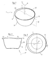
- the bowl 1 in Fig. 1 has a curved, relatively steep peripheral wall 3, which merges in the region of its upper bowl edge 6 end having in an outwardly flared zone 7 of less steepness. Below this outwardly flanged zone 7, the bowl 1 is rotationally symmetric with respect to the central axis 9, so that their cross-sections orthogonal to the axis 9 form circles.
- the center 11 is laterally offset relative to the bowl center axis 9.
- the bowl is constructed symmetrically with respect to the vertical center plane II, wherein the vertical center plane II intersects the outwardly flanged zone 7 at 13 at its radially widest point - and at 15 at its radially narrowest point (compare the sectional contour in FIG ).
- the outwardly flanged zone 7 forms an asymmetrically flared discharge rim with a spoiler lip with respect to the center axis 9, with the radial width of the outwardly flared zone continuously increasing from the narrowest point 15 to the widest point 13 along the circumference of the bowl 1.
- the wider area 13 of the issued pouring rim 7 is dimensioned so that it can be used as a handle portion for one-handed operation of the bowl.
- the pouring rim of varying width also allows a convenient metered pouring of liquids of different viscosities, with viscous media preferably via the wider area should be distributed at 13, as this area 13 offers favorable conditions for this, whereas low-viscosity media should be distributed over the narrow area 15, since this area 15 offers optimal conditions for this purpose.
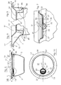
- the bowl 1 can be combined with a lid 17 according to FIGS. 4-10, as can be seen in the vertical sectional view according to FIG.
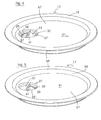
- the cover 17 comprises a cover plate 19 with an adjustable venting valve 21.
- the venting valve 21 has an indentation or recess 23 in the cover plate 19.
- This recess 23 is circular in plan view, with a circular half (in the figures at the left at 27) is perforated and thus has a plurality of small through-holes 25.
- the other circular half (in the figures at 29) of the recess 23 has no perforation.
- the recess 23 forms a receptacle for a about the central axis 31 of the recess rotatable valve closing element 33, which is rotatably supported by a sealed pivot bearing assembly 35 in the closing element receptacle 23.
- the pivot bearing assembly 35 is designed to allow easy disassembly of the vent valve 21 for cleaning purposes.
- the valve closing element 33 comprises a circular disk 37 which has at least one relatively large hole 39 in a circular half. This perforated circular half of the disc 37 adjoins approximately to an upwardly projecting handle bar 41, which extends over the diameter of the circular disc 37. The other circular half of the disc 37 has no perforation.
- the perforated half of the circular disc 37 can be brought into alignment with the perforated region 27 of the valve closing element receptacle 23, as can be seen in FIGS. 4 and 10.
- the valve closing member 33 is in the maximum open position and air exchange between the inside of the bowl 1 and the outside of the bowl 1 through the perforation holes 25 done.
- valve closing element 33 can be rotated into the closed position according to FIG. 5, in which the disc 37 sealingly overlaps the perforated region 27 of the closing element receptacle 23.
- the interior of the lid 1 covered bowl 1 is then sealed substantially airtight to the outside.
- at least one elastomeric seal 38 can be provided on the valve closing element 33, which still increases the sealing effect.
- cut-free areas are provided, which are provided for reducing friction.
- the grip portion 41 is not above the upper edge of the recess 23 from above, so that it can not form a disturbing contour when stacking.
- the cover plate 19 has a seal holder 49 in the form of a retaining ring on its plate side 47 defining the underside of the cover, on which an elastomer sealing ring 51 is held exchangeably.
- the sealing ring 51 is dimensioned such that in the intended arrangement of the cover 17 shown in FIGS. 6-9 it rests on the bowl 1 on the inner peripheral surface 53 of the bowl 1 in a circumferentially sealing manner.
- the elastomer seal ring 51 has a radially outwardly projecting seal lip 55 which circumferentially conforms to the inner peripheral surface 53 of the bowl 1 in the manner seen in Figs. 8 and 9.
- the lid 17 has a radially inner cover plate portion 57 containing the venting valve 21 and a radially outward edge portion 59, which is offset upwardly relative thereto, with which it rests on the bowl 1 on the upper edge of the bowl 6, as shown in FIGS. 6-9.
- the radially outer rim area 59 thus forms with the radially inner cover plate portion 57 a trough 61 which can receive the bottom of a similar further bowl when stacking.
- edge seam area 59 of the lid 17 is circumferentially bent downwards to overlap the upper edge 6 of the bowl 1 radially outward.
Landscapes
- Engineering & Computer Science (AREA)
- Food Science & Technology (AREA)
- Closures For Containers (AREA)
Applications Claiming Priority (1)
| Application Number | Priority Date | Filing Date | Title |
|---|---|---|---|
| DE102006028980A DE102006028980A1 (de) | 2006-06-23 | 2006-06-23 | Gefäß, insbesondere Schüssel für Koch-, Anricht-, Aufbewahrungs- oder/und Servierzwecke und Deckel für ein solches Gefäß |
Publications (2)
| Publication Number | Publication Date |
|---|---|
| EP1878366A2 true EP1878366A2 (fr) | 2008-01-16 |
| EP1878366A3 EP1878366A3 (fr) | 2009-03-11 |
Family
ID=38721169
Family Applications (1)
| Application Number | Title | Priority Date | Filing Date |
|---|---|---|---|
| EP07010295A Withdrawn EP1878366A3 (fr) | 2006-06-23 | 2007-05-23 | Récipient, en particulier saladier pour cuisson, présentation, garde et/ou service et couvercle pour un tel récipient |
Country Status (2)
| Country | Link |
|---|---|
| EP (1) | EP1878366A3 (fr) |
| DE (1) | DE102006028980A1 (fr) |
Cited By (3)
| Publication number | Priority date | Publication date | Assignee | Title |
|---|---|---|---|---|
| EP2103543A1 (fr) * | 2008-03-20 | 2009-09-23 | Adamo S.R.L. | Récipient alimentaire hermétique |
| EP2298144A1 (fr) * | 2009-09-16 | 2011-03-23 | Vorwerk & Co. Interholding GmbH | Récipient, notamment récipient de mélange pour une machine de cuisine |
| FR3029762A1 (fr) * | 2014-12-16 | 2016-06-17 | Bretagne Ceram Ind (B C I ) | Couvercle pour plat en ceramique |
Families Citing this family (1)
| Publication number | Priority date | Publication date | Assignee | Title |
|---|---|---|---|---|
| DE102009006817A1 (de) * | 2009-01-30 | 2010-08-05 | Hans Heidolph Gmbh & Co. Kg | Rotationsverdampfer |
Family Cites Families (8)
| Publication number | Priority date | Publication date | Assignee | Title |
|---|---|---|---|---|
| DE115482C (fr) * | ||||
| US1328001A (en) * | 1919-04-08 | 1920-01-13 | Hermon H Kinsman | Perforated utensil-cover |
| DE1837693U (de) * | 1957-03-04 | 1961-09-14 | Schuppener Siegwerk | Hohlkoerper, wie koch- oder bratgeschirr. |
| DE3905002A1 (de) * | 1989-02-18 | 1990-08-23 | Fissler Gmbh | Kochgefaess |
| US5203836A (en) * | 1992-01-10 | 1993-04-20 | Rubbermaid Incorporated | Nestable mixing bowl with integral handle |
| AT409078B (de) * | 1997-04-10 | 2002-05-27 | Linser Peter | Schale |
| DE29724514U1 (de) * | 1997-06-20 | 2001-09-06 | Sieger, Dieter, 48336 Sassenberg | Deckel aus Kunststoff zum luftdichten Verschließen von Behältnissen |
| US20040079755A1 (en) * | 2002-10-25 | 2004-04-29 | Richard Graus | Multi-functional lid for cookware |
-
2006
- 2006-06-23 DE DE102006028980A patent/DE102006028980A1/de not_active Ceased
-
2007
- 2007-05-23 EP EP07010295A patent/EP1878366A3/fr not_active Withdrawn
Cited By (5)
| Publication number | Priority date | Publication date | Assignee | Title |
|---|---|---|---|---|
| EP2103543A1 (fr) * | 2008-03-20 | 2009-09-23 | Adamo S.R.L. | Récipient alimentaire hermétique |
| EP2298144A1 (fr) * | 2009-09-16 | 2011-03-23 | Vorwerk & Co. Interholding GmbH | Récipient, notamment récipient de mélange pour une machine de cuisine |
| CN102018458A (zh) * | 2009-09-16 | 2011-04-20 | 德国福维克控股公司 | 容器,尤其是用于食品加工机的搅拌容器 |
| CN102018458B (zh) * | 2009-09-16 | 2014-12-24 | 德国福维克控股公司 | 一种用于食品加工机的容器 |
| FR3029762A1 (fr) * | 2014-12-16 | 2016-06-17 | Bretagne Ceram Ind (B C I ) | Couvercle pour plat en ceramique |
Also Published As
| Publication number | Publication date |
|---|---|
| EP1878366A3 (fr) | 2009-03-11 |
| DE102006028980A1 (de) | 2007-12-27 |
Similar Documents
| Publication | Publication Date | Title |
|---|---|---|
| DE10018685C2 (de) | Drehbarer, scheibenförmiger Schutzdeckel für ein Getränkebehältnis | |
| DE60223126T2 (de) | Deckel für Einweggetränkebehälter | |
| DE69911533T2 (de) | Vorratsbehälter | |
| CH662259A5 (de) | Streueinrichtung fuer aufnahme und abgabe einer wuerze. | |
| DE60219045T2 (de) | Wiederverschliessbarer behälterdeckel | |
| EP1878366A2 (fr) | Récipient, en particulier saladier pour cuisson, présentation, garde et/ou service et couvercle pour un tel récipient | |
| EP1812305B1 (fr) | Bouchon de fermeture | |
| DE69410547T2 (de) | Verabreichungsvorrichtung für feinspeisesalz | |
| DE102012107862A1 (de) | Küchengerät zum Aufsetzen auf ein Gefäß; Küchengeräte-Set, umfassend Küchengerät und verschiedene Funktionseinheiten | |
| EP1670692B1 (fr) | Contenant | |
| DE3201469A1 (de) | Wiederverschliessbarer metalldeckel fuer eine dose fuer fluessige fuellgueter | |
| DE69931264T2 (de) | Auslaufgeschütztes trinkbecher | |
| DE102010049727A1 (de) | Einstellbarer Trinkflaschenverschluß mit Trinkhalmfunktion | |
| DE102021129087B3 (de) | Gefäßdeckel | |
| WO2015096825A1 (fr) | Récipient de mélange pour mélanger des composants de produit d'éléments de récipients aptes à tourner et/ou coulisser | |
| DE4417037C2 (de) | Verfahren zum Herstellen eines Eßwerkzeugs | |
| DE19607691A1 (de) | Schaumkopf | |
| DE102005038673B4 (de) | Behälter | |
| DE102023132791B4 (de) | Verschlusseinheit zur Verbindung mit einer Trinkflasche | |
| DE29600164U1 (de) | Vorrichtung zum Öffnen von Glasampullen | |
| DE69701287T2 (de) | Bausatz für einen behälterverschluss | |
| EP3825284B1 (fr) | Filtre, en particulier filtre pour gourdes | |
| WO2019101779A1 (fr) | Couvercle de récipient, en particulier pour un mélangeur | |
| DE102020125048A1 (de) | Deckeldrücker und ein Verfahren zum Verschließen eines Bechers | |
| WO2025046499A1 (fr) | Couvercle de canette avec dispositif de fermeture refermable |
Legal Events
| Date | Code | Title | Description |
|---|---|---|---|
| PUAI | Public reference made under article 153(3) epc to a published international application that has entered the european phase |
Free format text: ORIGINAL CODE: 0009012 |
|
| AK | Designated contracting states |
Kind code of ref document: A2 Designated state(s): AT BE BG CH CY CZ DE DK EE ES FI FR GB GR HU IE IS IT LI LT LU LV MC MT NL PL PT RO SE SI SK TR |
|
| AX | Request for extension of the european patent |
Extension state: AL BA HR MK YU |
|
| PUAL | Search report despatched |
Free format text: ORIGINAL CODE: 0009013 |
|
| AK | Designated contracting states |
Kind code of ref document: A3 Designated state(s): AT BE BG CH CY CZ DE DK EE ES FI FR GB GR HU IE IS IT LI LT LU LV MC MT NL PL PT RO SE SI SK TR |
|
| AX | Request for extension of the european patent |
Extension state: AL BA HR MK RS |
|
| AKX | Designation fees paid |
Designated state(s): AT BE BG CH CY CZ DE DK EE ES FI FR GB GR HU IE IS IT LI LT LU LV MC MT NL PL PT RO SE SI SK TR |
|
| STAA | Information on the status of an ep patent application or granted ep patent |
Free format text: STATUS: THE APPLICATION IS DEEMED TO BE WITHDRAWN |
|
| 18D | Application deemed to be withdrawn |
Effective date: 20090912 |