EP1878519A1 - Tauchrohr - Google Patents
Tauchrohr Download PDFInfo
- Publication number
- EP1878519A1 EP1878519A1 EP06014520A EP06014520A EP1878519A1 EP 1878519 A1 EP1878519 A1 EP 1878519A1 EP 06014520 A EP06014520 A EP 06014520A EP 06014520 A EP06014520 A EP 06014520A EP 1878519 A1 EP1878519 A1 EP 1878519A1
- Authority
- EP
- European Patent Office
- Prior art keywords
- plate
- pouring nozzle
- nozzle according
- stiffening element
- pouring
- Prior art date
- Legal status (The legal status is an assumption and is not a legal conclusion. Google has not performed a legal analysis and makes no representation as to the accuracy of the status listed.)
- Granted
Links
- 239000011819 refractory material Substances 0.000 claims description 15
- 230000035939 shock Effects 0.000 claims description 4
- 239000000919 ceramic Substances 0.000 claims description 2
- 239000002184 metal Substances 0.000 abstract description 7
- 239000000161 steel melt Substances 0.000 abstract description 2
- 239000011214 refractory ceramic Substances 0.000 description 6
- 229910010293 ceramic material Inorganic materials 0.000 description 5
- 239000000463 material Substances 0.000 description 4
- 230000002787 reinforcement Effects 0.000 description 3
- 238000005452 bending Methods 0.000 description 2
- 230000000694 effects Effects 0.000 description 2
- 238000005058 metal casting Methods 0.000 description 2
- 230000002093 peripheral effect Effects 0.000 description 2
- 230000007704 transition Effects 0.000 description 2
- 230000015572 biosynthetic process Effects 0.000 description 1
- 238000005094 computer simulation Methods 0.000 description 1
- 238000005538 encapsulation Methods 0.000 description 1
- 238000009434 installation Methods 0.000 description 1
- 238000004519 manufacturing process Methods 0.000 description 1
- 230000008018 melting Effects 0.000 description 1
- 238000002844 melting Methods 0.000 description 1
- 230000000930 thermomechanical effect Effects 0.000 description 1
Images
Classifications
-
- B—PERFORMING OPERATIONS; TRANSPORTING
- B22—CASTING; POWDER METALLURGY
- B22D—CASTING OF METALS; CASTING OF OTHER SUBSTANCES BY THE SAME PROCESSES OR DEVICES
- B22D41/00—Casting melt-holding vessels, e.g. ladles, tundishes, cups or the like
- B22D41/50—Pouring-nozzles
Definitions
- the invention relates to a pouring nozzle.
- Such pouring nozzle may be used for the transfer of a metal melt from one (upper) metallurgical vessel to a second (lower) metallurgical vessel, for example for the transfer of a steel melt from a ladle to a tundish.
- Such pouring nozzles are made of at least one refractory material (to withstand the high melt temperatures) and comprise a tubular region, defining a first part of a pouring channel, and a plate like region with an orifice defining a second part of said (common) pouring channel. Said plate like region which usually is integral with said tubular region is arranged at one end of the tubular member. This leads to a T-like design of the total pouring nozzle.
- two of said pouring nozzles are arranged in the outflow area of a metallurgical melting vessel.
- One of said two nozzles being mostly arranged within the refractory lining of the vessel, e.g. within a well block.
- This so called inner nozzle is mounted with its tubular region at its upper end and the plate like region at its lower end.
- the plate like region may be used as one part of a sliding gate valve.
- the plate like region has a flat surface at its free (lower) end, which flat surface running perpendicular to a longitudinal axis of the pouring channel, i. e. more or less horizontal in the mounted position of the pouring nozzle.
- a second nozzle (often called outer nozzle or exchange nozzle) may be installed below said inner nozzle, e.g. mounted vice versa with its plate like part at its upper end and the tubular part at its lower end.
- This nozzle often may be moved after installation.
- the free surface of the plate like region should be flat so as it may be used as a sliding surface within a 2 or 3 plates sliding mechanism.
- a metallic envelope metal casing
- This casing stabilizes the nozzle and facilitates the exchange of the nozzle.
- the metallic can further provides the necessary geometrical accuracy for effective fit with a corresponding operational or exchange mechanism and mechanical support to the relatively brittle refractory ceramic nozzle components.
- thermo-mechanical forces established during preheat of the nozzle Due to a combination of thermo-mechanical forces established during preheat of the nozzle, exchange motion and/or cast operation stresses are created within the nozzle which may result in cracks through its wall, especially at the transition area where the plate and tubular portions meet.
- the inventors have analyzed by computer simulation studies the origins of said crack formation. It was noted that for the lower (moving) element the highest stresses occur over the support mechanism for said nozzle and being greatest at the central transverse axis over the loading mechanism. In the classical "T" form of a pouring nozzle these support forces create a highly stressed zone between the support surface and the pouring channel along which a crack may propagate from the exterior to the bore (pouring channel) of the tube section under the support flange (the plate like member).
- the invention in its most general embodiment relates to a pouring nozzle made of at least one refractory material and comprising a tubular member defining a first part of a pouring channel and a plate like member integral with said tubular member and projecting from the tubular member along its periphery at the one end, said plate like member having an orifice defining a second part of said pouring channel and a flat surface at its free end, which flat surface running perpendicular to a longitudinal axis of said pouring channel, at least part of the plate like member and/or of the tubular member being encapsulated by a metallic envelope, wherein at least one stiffening element is arranged within the refractory material of said plate like member, between said plate like member and the metallic envelope or protruding from said metallic envelope into the said plate like member.
- the design configuration of the external encapsulation facilitates introduction of integral stiffening within the support can.
- the extra rigidity provided by such integral, internal stiffening elements introduces the potential to absorb the point loading forces from a corresponding support mechanism and distribute any such forces evenly across a wide area of the encapsulated refractory ceramic material and thereby onto the head and tubular regions of the nozzle.
- the pouring nozzle comprises two stiffening elements, arranged at opposite ends of said plate like member.
- the plate like member is shaped as a parallelepiped, especially when used within a sliding gate arrangement. It then comprises two (of four) opposite support flanges against which the support mechanism acts.
- the stiffening elements may have various shapes. They can be shaped as a rod, as a helical spring, as a bar or the like.
- the plate like member may have the shape of a ring.
- the stiffening element may be fully surrounded by refractory ceramic material (first alternative). It may also be arranged between the refractory ceramic material and the metallic envelope (alternative 2). In alternative 3 the reinforcement member is part of the metallic envelope and arranged like a flange along the inner wall of said envelope. All these three embodiments will be further disclosed by examples hereinafter.
- the stiffening element may be arranged such that one of its surfaces forms part of the flat surface of the plate like member. It is then preferably arranged at the outer periphery of the flat surface of the plate like member. This minimizes the risk of any deflection in the outer peripheral region of the plate like member according to figure 1.
- a shock absorbing interface zone may be arranged between the basic (inner) refractory material and the stiffening element(s) and/or the (outer) metallic envelope.
- Said shock absorbing interface zone may be made of a second refractory material which becomes deformable at temperatures experienced during use of said pouring nozzle in metal casting.
- the inventive concept may be applied to pouring nozzles of a strong T-shape, i. e. nozzles comprising a plate like region the supporting surfaces of which running more or less parallel to the flat surface at their free end.
- the concept may as well be applied to nozzles according to figure 3 of EP 1 133 373 B1 (identical to nozzles according to EP 1 590 114 B1 ) comprising bearing surfaces (opposite the free flat surface) which bearing surfaces form an angle unequal 90° with the longitudinal axis of the pouring channel.
- part(s) of the stiffening element(s) form part of the chamfered surface sections (bearing surfaces).
- the stiffening element(s) may be made of any material improving the manufacturing, use or exchange of a pouring nozzle for metal casting.
- One of the most favourite materials is metal but a ceramic of high modulus of rupture may be favourite as well.
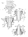
- Figure 1 shows an inner nozzle 10 and an outer nozzle 12 of a generally T-shaped design with flanges of similar geometric design but both nozzles 10, 12 could as well be characterised by identical designs.
- Nozzle 12 of figure 2 comprises a tubular region 12t defining a first part of pouring channel 14.
- Said tubular part 12t is made from a common refractory ceramic material and is integral with a plate like region 12p following upwardly.
- Said plate like region 12p is of larger cross sectional area than part 12t and comprises an inner part 12pi made of the same refractory material as tubular member 12t and two metallic parts 12pm running alongside two opposite sides of the inner part 12pi. While the inner surfaces of the metallic parts 12pm are touching the corresponding outer surface areas of the refractory part 12pi the outer surfaces of part 12m are in contact with an envelope 16, as described hereinafter.
- Said plate like member 12p provides a flat upper surface 12s at its free end (opposite tubular part 12t) which surface 12s being defined by a combination of corresponding surfaces of the refractory part 12pi and said two metal reinforcement inserts 12pm, presenting stiffening elements.
- the said stiffening elements are characterised by an upper vertical outer surface 12pmo, followed by an inclined surface portion 12pmi while the respective inner walls are running vertical from upper surface 12s to the respective lower ends.
- a metallic can 16 encapsulates the plate like member 12p and the annexed area of tubular member 12t.
- the longitudinal axis of this nozzle 12 is marked as "L”.
- nozzle 12 of figure 1 When nozzle 12 of figure 1 is replaced by one incorporating the design shown in figure 2 with the integral stiffening members, the temperature conditions arising from service again generate a differential thermal deflection across the plate surface 12s. However the said stiffening elements 12pm bear the pressures from the closing mechanism and prevent them from establishing any bending stress moment across the refractory material of the nozzle 12.
- nozzle 12 according to figure 2 provides the further advantage that its chamfered bearing surfaces, provided by the can sections opposite surface sections 12pmi present increased mechanical stability because the stiffening elements 12pm are arranged directly behind this bearing surfaces.
- a similar effect may be achieved by a pouring nozzle 12 according to figure 4 which differs from that of figure 2 just in the arrangement of said two stiffening elements 12pm.
- Both stiffening elements 12pm are designed as rods (bars) and placed within the refractory ceramic material of plate like member 12p, i.e. they are fully surrounded by said refractory material.
- the respective cross sectional area is adapted to the outer design of plate like member 12p.
- Especially said stiffening element 12pm provides inclined lower surface sections 12pmi running parallel to corresponding inclined bearing surfaces 16b of metal can 16.
- Figure 3 represents a pouring nozzle 10 used as an inner nozzle according to inner nozzle 10 of figure 1.
- Nozzle 10 again comprises a tubular part 10t followed (here: at its lower end) by a plate like part 10p.
- the transition area between tubular part 10t and plate like part 10p is marked as "T”.
- Figure 3 shows that tubular part 10t is - at its lower end - surrounded by a sleeve 18, made of a refractory material different to that of part 10t.
- This sleeve 18 continues around the plate like member 10p and in turn is encapsulated by an outer metallic envelope 16 which ends shortly before the free and flat surface area 10s at the lower end of nozzle 10.
- a shock absorbing interface layer "S" made from a material which becomes deformable at the temperatures experienced during use of said pouring nozzle, may be introduced between the refractory pouring nozzle element 10p and the second surrounding refractory sleeve 18.
- can 16 Following the shape of sleeve 18 can 16 is characterised by a cylindrical part at its upper end, followed by an inclined (outwardly extending) portion 16b and an outwardly extending horizontal part 16h followed by a final vertically running portion 16v.
- That part of envelope 16 provided by horizontal part 16h and vertical portion 16v is mechanically reinforced by two stiffening elements 10pm, protruding from opposing inner wall of envelope 16.
- Both of said stiffening elements are designed as rods with a rectangular square section. They are replacing part of encapsulating material of sleeve 18.
- the refractory material of tubular part 10t extends into the area of plate like member 10p and is characterised by an outwardly tapered portion 10pi providing the inner part of surface section 10s around the pouring channel 14.
- the two metal bars 10pm again act as stiffening elements similar to stiffening elements in figures 2 and 4. According to the embodiment of figure 3 theses stiffening elements 10pm are integral part of the outer metallic envelope 16.
- the shape of the can and any adjacent stiffening means like 12pm or 10pm in any of the embodiments shown may have a profile suited to any specific mechanism configuration.
Landscapes
- Engineering & Computer Science (AREA)
- Mechanical Engineering (AREA)
- Casting Support Devices, Ladles, And Melt Control Thereby (AREA)
- Continuous Casting (AREA)
- Nozzles (AREA)
- Supply Of Fluid Materials To The Packaging Location (AREA)
- Turbine Rotor Nozzle Sealing (AREA)
- Glass Compositions (AREA)
- Resistance Heating (AREA)
- Lift Valve (AREA)
Priority Applications (13)
| Application Number | Priority Date | Filing Date | Title |
|---|---|---|---|
| ES06014520T ES2300084T3 (es) | 2006-07-13 | 2006-07-13 | Boquilla de colada. |
| EP06014520A EP1878519B1 (de) | 2006-07-13 | 2006-07-13 | Tauchrohr |
| AT06014520T ATE387276T1 (de) | 2006-07-13 | 2006-07-13 | Tauchrohr |
| DE602006000598T DE602006000598T2 (de) | 2006-07-13 | 2006-07-13 | Gießrohr |
| PL06014520T PL1878519T3 (pl) | 2006-07-13 | 2006-07-13 | Wylew kadziowy |
| PCT/EP2007/005271 WO2008006438A1 (en) | 2006-07-13 | 2007-06-15 | Pouring nozzle |
| CNA2007800263096A CN101547761A (zh) | 2006-07-13 | 2007-06-15 | 浇注喷嘴 |
| US12/305,366 US20090173757A1 (en) | 2006-07-13 | 2007-06-15 | Pouring nozzle |
| RU2008152194/02A RU2393054C1 (ru) | 2006-07-13 | 2007-06-15 | Разливочный стакан |
| BRPI0713922-5A BRPI0713922A2 (pt) | 2006-07-13 | 2007-06-15 | válvula de lingotamento |
| UAA200900173A UA93916C2 (en) | 2006-07-13 | 2007-06-15 | Pouring nozzle |
| MX2009000332A MX2009000332A (es) | 2006-07-13 | 2007-06-15 | Boquilla surtidora. |
| ZA200900015A ZA200900015B (en) | 2006-07-13 | 2009-01-05 | Pouring nozzle |
Applications Claiming Priority (1)
| Application Number | Priority Date | Filing Date | Title |
|---|---|---|---|
| EP06014520A EP1878519B1 (de) | 2006-07-13 | 2006-07-13 | Tauchrohr |
Publications (2)
| Publication Number | Publication Date |
|---|---|
| EP1878519A1 true EP1878519A1 (de) | 2008-01-16 |
| EP1878519B1 EP1878519B1 (de) | 2008-02-27 |
Family
ID=37460121
Family Applications (1)
| Application Number | Title | Priority Date | Filing Date |
|---|---|---|---|
| EP06014520A Not-in-force EP1878519B1 (de) | 2006-07-13 | 2006-07-13 | Tauchrohr |
Country Status (13)
| Country | Link |
|---|---|
| US (1) | US20090173757A1 (de) |
| EP (1) | EP1878519B1 (de) |
| CN (1) | CN101547761A (de) |
| AT (1) | ATE387276T1 (de) |
| BR (1) | BRPI0713922A2 (de) |
| DE (1) | DE602006000598T2 (de) |
| ES (1) | ES2300084T3 (de) |
| MX (1) | MX2009000332A (de) |
| PL (1) | PL1878519T3 (de) |
| RU (1) | RU2393054C1 (de) |
| UA (1) | UA93916C2 (de) |
| WO (1) | WO2008006438A1 (de) |
| ZA (1) | ZA200900015B (de) |
Cited By (3)
| Publication number | Priority date | Publication date | Assignee | Title |
|---|---|---|---|---|
| WO2014042611A1 (en) * | 2012-09-11 | 2014-03-20 | Refractory Intellectual Property Gmbh & Co. Kg | Refractory pouring device |
| WO2015171114A1 (en) * | 2014-05-05 | 2015-11-12 | Refractory Intellectual Property Gmbh & Co. Kg | Refractory ceramic casting nozzle |
| EP3112050A4 (de) * | 2014-02-25 | 2017-10-18 | Krosakiharima Corporation | Unterwasserdüse |
Families Citing this family (2)
| Publication number | Priority date | Publication date | Assignee | Title |
|---|---|---|---|---|
| CN104249210A (zh) * | 2013-06-28 | 2014-12-31 | 鸿富锦精密工业(深圳)有限公司 | 多点焊治具 |
| UA123573U (uk) * | 2017-11-10 | 2018-02-26 | Товариство З Обмеженою Відповідальністю "Шеффілд Рефракторіс Україна" | Стакан-дозатор для розливання металів і сплавів |
Citations (4)
| Publication number | Priority date | Publication date | Assignee | Title |
|---|---|---|---|---|
| JPS62124071A (ja) * | 1985-11-21 | 1987-06-05 | Nippon Steel Corp | 溶融金属注入用ノズル |
| JPH11104793A (ja) * | 1997-10-02 | 1999-04-20 | Akechi Ceramics Kk | 連続鋳造用ロングノズル |
| EP1149649A1 (de) * | 2000-04-28 | 2001-10-31 | Akechi Ceramics Kabushiki Kaisha | Auswechselbare Giessdüze zum Kontinuierlichen Giessen |
| EP1140394B1 (de) * | 1998-12-15 | 2003-04-16 | Vesuvius Crucible Company | Giessrohr |
Family Cites Families (4)
| Publication number | Priority date | Publication date | Assignee | Title |
|---|---|---|---|---|
| GB1490981A (en) * | 1974-01-15 | 1977-11-09 | Flogates Ltd | Pouring of molten metals |
| GB9222453D0 (en) * | 1992-10-26 | 1992-12-09 | Shaw Richard D | Improved device for use in continuous casting |
| US5954989A (en) * | 1997-03-20 | 1999-09-21 | Vesuvius Crucible Company | Erosion and abrasion resistant refractory composition and article made therefrom |
| GB9825986D0 (en) * | 1998-11-27 | 1999-01-20 | Didier Werke Ag | Improvements in or relating to refractory products |
-
2006
- 2006-07-13 DE DE602006000598T patent/DE602006000598T2/de active Active
- 2006-07-13 EP EP06014520A patent/EP1878519B1/de not_active Not-in-force
- 2006-07-13 ES ES06014520T patent/ES2300084T3/es active Active
- 2006-07-13 PL PL06014520T patent/PL1878519T3/pl unknown
- 2006-07-13 AT AT06014520T patent/ATE387276T1/de not_active IP Right Cessation
-
2007
- 2007-06-15 RU RU2008152194/02A patent/RU2393054C1/ru not_active IP Right Cessation
- 2007-06-15 US US12/305,366 patent/US20090173757A1/en not_active Abandoned
- 2007-06-15 MX MX2009000332A patent/MX2009000332A/es not_active Application Discontinuation
- 2007-06-15 WO PCT/EP2007/005271 patent/WO2008006438A1/en not_active Ceased
- 2007-06-15 CN CNA2007800263096A patent/CN101547761A/zh active Pending
- 2007-06-15 BR BRPI0713922-5A patent/BRPI0713922A2/pt not_active IP Right Cessation
- 2007-06-15 UA UAA200900173A patent/UA93916C2/ru unknown
-
2009
- 2009-01-05 ZA ZA200900015A patent/ZA200900015B/xx unknown
Patent Citations (4)
| Publication number | Priority date | Publication date | Assignee | Title |
|---|---|---|---|---|
| JPS62124071A (ja) * | 1985-11-21 | 1987-06-05 | Nippon Steel Corp | 溶融金属注入用ノズル |
| JPH11104793A (ja) * | 1997-10-02 | 1999-04-20 | Akechi Ceramics Kk | 連続鋳造用ロングノズル |
| EP1140394B1 (de) * | 1998-12-15 | 2003-04-16 | Vesuvius Crucible Company | Giessrohr |
| EP1149649A1 (de) * | 2000-04-28 | 2001-10-31 | Akechi Ceramics Kabushiki Kaisha | Auswechselbare Giessdüze zum Kontinuierlichen Giessen |
Cited By (5)
| Publication number | Priority date | Publication date | Assignee | Title |
|---|---|---|---|---|
| WO2014042611A1 (en) * | 2012-09-11 | 2014-03-20 | Refractory Intellectual Property Gmbh & Co. Kg | Refractory pouring device |
| EP3112050A4 (de) * | 2014-02-25 | 2017-10-18 | Krosakiharima Corporation | Unterwasserdüse |
| WO2015171114A1 (en) * | 2014-05-05 | 2015-11-12 | Refractory Intellectual Property Gmbh & Co. Kg | Refractory ceramic casting nozzle |
| JP2017514692A (ja) * | 2014-05-05 | 2017-06-08 | リフラクトリー・インテレクチュアル・プロパティー・ゲー・エム・ベー・ハー・ウント・コ・カーゲー | 耐火性セラミック鋳造ノズル |
| US10232435B2 (en) | 2014-05-05 | 2019-03-19 | Refractory Intellectual Property Gmbh & Co. Kg | Refractory ceramic casting nozzle |
Also Published As
| Publication number | Publication date |
|---|---|
| RU2393054C1 (ru) | 2010-06-27 |
| WO2008006438A1 (en) | 2008-01-17 |
| BRPI0713922A2 (pt) | 2012-11-27 |
| PL1878519T3 (pl) | 2008-06-30 |
| DE602006000598D1 (de) | 2008-04-10 |
| ES2300084T3 (es) | 2008-06-01 |
| US20090173757A1 (en) | 2009-07-09 |
| EP1878519B1 (de) | 2008-02-27 |
| ATE387276T1 (de) | 2008-03-15 |
| CN101547761A (zh) | 2009-09-30 |
| DE602006000598T2 (de) | 2009-03-26 |
| UA93916C2 (en) | 2011-03-25 |
| ZA200900015B (en) | 2009-12-30 |
| MX2009000332A (es) | 2009-01-29 |
Similar Documents
| Publication | Publication Date | Title |
|---|---|---|
| WO2008006438A1 (en) | Pouring nozzle | |
| CA2323348C (en) | Exchangeable continuous casting nozzle | |
| JP5001213B2 (ja) | 連続鋳造用浸漬ノズル | |
| JP4308288B2 (ja) | 溶解炉の出銑口構造およびその補修方法 | |
| KR20160147718A (ko) | 내화성 세라믹 캐스팅 노즐 | |
| RU2466825C2 (ru) | Разливочный стакан для непрерывного литья | |
| AU754513B2 (en) | Pouring tube | |
| AU732248B2 (en) | Pouring tube structure and assembly | |
| CA2352299C (en) | Improvements in or relating to refractory products | |
| EP2407262B1 (de) | Gussdüse | |
| SE430035B (sv) | Sjelvberande slidplatta | |
| CN104540619A (zh) | 耐火浇铸装置 | |
| EP1724036B1 (de) | Verschlussvorrichtung zur Regulierung eines Schmelzflusses | |
| EP1621270B1 (de) | Langgestreckte Stopfenstange | |
| JP3016335U (ja) | モルタル落下防止ノズル保持ケース | |
| US11117187B2 (en) | Casting nozzle | |
| GB2344304A (en) | A refractory device with a pyroplastic interface zone which deforms at high temperatures | |
| WO2006007933A1 (en) | An elongated stopper device | |
| KR20070073420A (ko) | 슬리브블럭을 구비한 버블링플러그 | |
| JPH03198959A (ja) | タンディッシュストッパー |
Legal Events
| Date | Code | Title | Description |
|---|---|---|---|
| GRAP | Despatch of communication of intention to grant a patent |
Free format text: ORIGINAL CODE: EPIDOSNIGR1 |
|
| PUAI | Public reference made under article 153(3) epc to a published international application that has entered the european phase |
Free format text: ORIGINAL CODE: 0009012 |
|
| 17P | Request for examination filed |
Effective date: 20070518 |
|
| AK | Designated contracting states |
Kind code of ref document: A1 Designated state(s): AT BE BG CH CY CZ DE DK EE ES FI FR GB GR HU IE IS IT LI LT LU LV MC NL PL PT RO SE SI SK TR |
|
| AX | Request for extension of the european patent |
Extension state: AL BA HR MK YU |
|
| GRAS | Grant fee paid |
Free format text: ORIGINAL CODE: EPIDOSNIGR3 |
|
| GRAA | (expected) grant |
Free format text: ORIGINAL CODE: 0009210 |
|
| AK | Designated contracting states |
Kind code of ref document: B1 Designated state(s): AT BE BG CH CY CZ DE DK EE ES FI FR GB GR HU IE IS IT LI LT LU LV MC NL PL PT RO SE SI SK TR |
|
| REG | Reference to a national code |
Ref country code: GB Ref legal event code: FG4D |
|
| REG | Reference to a national code |
Ref country code: CH Ref legal event code: EP |
|
| REG | Reference to a national code |
Ref country code: IE Ref legal event code: FG4D |
|
| REF | Corresponds to: |
Ref document number: 602006000598 Country of ref document: DE Date of ref document: 20080410 Kind code of ref document: P |
|
| REG | Reference to a national code |
Ref country code: RO Ref legal event code: EPE |
|
| REG | Reference to a national code |
Ref country code: SE Ref legal event code: TRGR |
|
| REG | Reference to a national code |
Ref country code: ES Ref legal event code: FG2A Ref document number: 2300084 Country of ref document: ES Kind code of ref document: T3 |
|
| REG | Reference to a national code |
Ref country code: PL Ref legal event code: T3 |
|
| PG25 | Lapsed in a contracting state [announced via postgrant information from national office to epo] |
Ref country code: FI Free format text: LAPSE BECAUSE OF FAILURE TO SUBMIT A TRANSLATION OF THE DESCRIPTION OR TO PAY THE FEE WITHIN THE PRESCRIBED TIME-LIMIT Effective date: 20080227 Ref country code: IS Free format text: LAPSE BECAUSE OF FAILURE TO SUBMIT A TRANSLATION OF THE DESCRIPTION OR TO PAY THE FEE WITHIN THE PRESCRIBED TIME-LIMIT Effective date: 20080627 |
|
| NLV1 | Nl: lapsed or annulled due to failure to fulfill the requirements of art. 29p and 29m of the patents act | ||
| PG25 | Lapsed in a contracting state [announced via postgrant information from national office to epo] |
Ref country code: AT Free format text: LAPSE BECAUSE OF FAILURE TO SUBMIT A TRANSLATION OF THE DESCRIPTION OR TO PAY THE FEE WITHIN THE PRESCRIBED TIME-LIMIT Effective date: 20080227 |
|
| AKX | Designation fees paid |
Designated state(s): AT BE BG CH CY CZ DE DK EE ES FI FR GB GR HU IE IS IT LI LT LU LV MC NL PL PT RO SE SI SK TR |
|
| PG25 | Lapsed in a contracting state [announced via postgrant information from national office to epo] |
Ref country code: LV Free format text: LAPSE BECAUSE OF FAILURE TO SUBMIT A TRANSLATION OF THE DESCRIPTION OR TO PAY THE FEE WITHIN THE PRESCRIBED TIME-LIMIT Effective date: 20080227 Ref country code: SI Free format text: LAPSE BECAUSE OF FAILURE TO SUBMIT A TRANSLATION OF THE DESCRIPTION OR TO PAY THE FEE WITHIN THE PRESCRIBED TIME-LIMIT Effective date: 20080227 Ref country code: BE Free format text: LAPSE BECAUSE OF FAILURE TO SUBMIT A TRANSLATION OF THE DESCRIPTION OR TO PAY THE FEE WITHIN THE PRESCRIBED TIME-LIMIT Effective date: 20080227 |
|
| ET | Fr: translation filed | ||
| PG25 | Lapsed in a contracting state [announced via postgrant information from national office to epo] |
Ref country code: SK Free format text: LAPSE BECAUSE OF FAILURE TO SUBMIT A TRANSLATION OF THE DESCRIPTION OR TO PAY THE FEE WITHIN THE PRESCRIBED TIME-LIMIT Effective date: 20080227 Ref country code: PT Free format text: LAPSE BECAUSE OF FAILURE TO SUBMIT A TRANSLATION OF THE DESCRIPTION OR TO PAY THE FEE WITHIN THE PRESCRIBED TIME-LIMIT Effective date: 20080721 Ref country code: NL Free format text: LAPSE BECAUSE OF FAILURE TO SUBMIT A TRANSLATION OF THE DESCRIPTION OR TO PAY THE FEE WITHIN THE PRESCRIBED TIME-LIMIT Effective date: 20080227 Ref country code: DK Free format text: LAPSE BECAUSE OF FAILURE TO SUBMIT A TRANSLATION OF THE DESCRIPTION OR TO PAY THE FEE WITHIN THE PRESCRIBED TIME-LIMIT Effective date: 20080227 Ref country code: CZ Free format text: LAPSE BECAUSE OF FAILURE TO SUBMIT A TRANSLATION OF THE DESCRIPTION OR TO PAY THE FEE WITHIN THE PRESCRIBED TIME-LIMIT Effective date: 20080227 |
|
| PLBE | No opposition filed within time limit |
Free format text: ORIGINAL CODE: 0009261 |
|
| STAA | Information on the status of an ep patent application or granted ep patent |
Free format text: STATUS: NO OPPOSITION FILED WITHIN TIME LIMIT |
|
| PG25 | Lapsed in a contracting state [announced via postgrant information from national office to epo] |
Ref country code: LT Free format text: LAPSE BECAUSE OF FAILURE TO SUBMIT A TRANSLATION OF THE DESCRIPTION OR TO PAY THE FEE WITHIN THE PRESCRIBED TIME-LIMIT Effective date: 20080227 |
|
| 26N | No opposition filed |
Effective date: 20081128 |
|
| PG25 | Lapsed in a contracting state [announced via postgrant information from national office to epo] |
Ref country code: MC Free format text: LAPSE BECAUSE OF NON-PAYMENT OF DUE FEES Effective date: 20080731 |
|
| PG25 | Lapsed in a contracting state [announced via postgrant information from national office to epo] |
Ref country code: BG Free format text: LAPSE BECAUSE OF FAILURE TO SUBMIT A TRANSLATION OF THE DESCRIPTION OR TO PAY THE FEE WITHIN THE PRESCRIBED TIME-LIMIT Effective date: 20080527 Ref country code: EE Free format text: LAPSE BECAUSE OF FAILURE TO SUBMIT A TRANSLATION OF THE DESCRIPTION OR TO PAY THE FEE WITHIN THE PRESCRIBED TIME-LIMIT Effective date: 20080227 |
|
| PG25 | Lapsed in a contracting state [announced via postgrant information from national office to epo] |
Ref country code: IE Free format text: LAPSE BECAUSE OF NON-PAYMENT OF DUE FEES Effective date: 20080714 Ref country code: CY Free format text: LAPSE BECAUSE OF FAILURE TO SUBMIT A TRANSLATION OF THE DESCRIPTION OR TO PAY THE FEE WITHIN THE PRESCRIBED TIME-LIMIT Effective date: 20080227 |
|
| PG25 | Lapsed in a contracting state [announced via postgrant information from national office to epo] |
Ref country code: HU Free format text: LAPSE BECAUSE OF FAILURE TO SUBMIT A TRANSLATION OF THE DESCRIPTION OR TO PAY THE FEE WITHIN THE PRESCRIBED TIME-LIMIT Effective date: 20080828 Ref country code: LU Free format text: LAPSE BECAUSE OF NON-PAYMENT OF DUE FEES Effective date: 20080713 |
|
| PG25 | Lapsed in a contracting state [announced via postgrant information from national office to epo] |
Ref country code: GR Free format text: LAPSE BECAUSE OF FAILURE TO SUBMIT A TRANSLATION OF THE DESCRIPTION OR TO PAY THE FEE WITHIN THE PRESCRIBED TIME-LIMIT Effective date: 20080528 |
|
| REG | Reference to a national code |
Ref country code: CH Ref legal event code: PL |
|
| PG25 | Lapsed in a contracting state [announced via postgrant information from national office to epo] |
Ref country code: LI Free format text: LAPSE BECAUSE OF NON-PAYMENT OF DUE FEES Effective date: 20100731 Ref country code: CH Free format text: LAPSE BECAUSE OF NON-PAYMENT OF DUE FEES Effective date: 20100731 |
|
| PGFP | Annual fee paid to national office [announced via postgrant information from national office to epo] |
Ref country code: TR Payment date: 20110630 Year of fee payment: 6 |
|
| PGFP | Annual fee paid to national office [announced via postgrant information from national office to epo] |
Ref country code: FR Payment date: 20110729 Year of fee payment: 6 |
|
| PGFP | Annual fee paid to national office [announced via postgrant information from national office to epo] |
Ref country code: ES Payment date: 20110728 Year of fee payment: 6 Ref country code: DE Payment date: 20110728 Year of fee payment: 6 Ref country code: PL Payment date: 20110711 Year of fee payment: 6 Ref country code: GB Payment date: 20110721 Year of fee payment: 6 Ref country code: RO Payment date: 20110704 Year of fee payment: 6 Ref country code: SE Payment date: 20110721 Year of fee payment: 6 |
|
| PGFP | Annual fee paid to national office [announced via postgrant information from national office to epo] |
Ref country code: IT Payment date: 20110726 Year of fee payment: 6 |
|
| REG | Reference to a national code |
Ref country code: SE Ref legal event code: EUG |
|
| GBPC | Gb: european patent ceased through non-payment of renewal fee |
Effective date: 20120713 |
|
| REG | Reference to a national code |
Ref country code: FR Ref legal event code: ST Effective date: 20130329 |
|
| PG25 | Lapsed in a contracting state [announced via postgrant information from national office to epo] |
Ref country code: SE Free format text: LAPSE BECAUSE OF NON-PAYMENT OF DUE FEES Effective date: 20120714 Ref country code: DE Free format text: LAPSE BECAUSE OF NON-PAYMENT OF DUE FEES Effective date: 20130201 Ref country code: GB Free format text: LAPSE BECAUSE OF NON-PAYMENT OF DUE FEES Effective date: 20120713 Ref country code: FR Free format text: LAPSE BECAUSE OF NON-PAYMENT OF DUE FEES Effective date: 20120731 |
|
| PG25 | Lapsed in a contracting state [announced via postgrant information from national office to epo] |
Ref country code: IT Free format text: LAPSE BECAUSE OF NON-PAYMENT OF DUE FEES Effective date: 20120713 |
|
| PG25 | Lapsed in a contracting state [announced via postgrant information from national office to epo] |
Ref country code: RO Free format text: LAPSE BECAUSE OF NON-PAYMENT OF DUE FEES Effective date: 20120713 |
|
| REG | Reference to a national code |
Ref country code: DE Ref legal event code: R119 Ref document number: 602006000598 Country of ref document: DE Effective date: 20130201 |
|
| REG | Reference to a national code |
Ref country code: PL Ref legal event code: LAPE |
|
| PG25 | Lapsed in a contracting state [announced via postgrant information from national office to epo] |
Ref country code: PL Free format text: LAPSE BECAUSE OF NON-PAYMENT OF DUE FEES Effective date: 20120713 |
|
| REG | Reference to a national code |
Ref country code: ES Ref legal event code: FD2A Effective date: 20140109 |
|
| PG25 | Lapsed in a contracting state [announced via postgrant information from national office to epo] |
Ref country code: ES Free format text: LAPSE BECAUSE OF NON-PAYMENT OF DUE FEES Effective date: 20120714 |
|
| PG25 | Lapsed in a contracting state [announced via postgrant information from national office to epo] |
Ref country code: TR Free format text: LAPSE BECAUSE OF NON-PAYMENT OF DUE FEES Effective date: 20120713 |