EP1878548A1 - Scie circulaire pour bois de chauffage - Google Patents
Scie circulaire pour bois de chauffage Download PDFInfo
- Publication number
- EP1878548A1 EP1878548A1 EP07013343A EP07013343A EP1878548A1 EP 1878548 A1 EP1878548 A1 EP 1878548A1 EP 07013343 A EP07013343 A EP 07013343A EP 07013343 A EP07013343 A EP 07013343A EP 1878548 A1 EP1878548 A1 EP 1878548A1
- Authority
- EP
- European Patent Office
- Prior art keywords
- saw blade
- circular saw
- firewood
- firewood circular
- saw according
- Prior art date
- Legal status (The legal status is an assumption and is not a legal conclusion. Google has not performed a legal analysis and makes no representation as to the accuracy of the status listed.)
- Granted
Links
Images

Classifications
-
- B—PERFORMING OPERATIONS; TRANSPORTING
- B27—WORKING OR PRESERVING WOOD OR SIMILAR MATERIAL; NAILING OR STAPLING MACHINES IN GENERAL
- B27B—SAWS FOR WOOD OR SIMILAR MATERIAL; COMPONENTS OR ACCESSORIES THEREFOR
- B27B5/00—Sawing machines working with circular or cylindrical saw blades; Components or equipment therefor
- B27B5/16—Saw benches
- B27B5/22—Saw benches with non-feedable circular saw blade
- B27B5/224—Saw benches with non-feedable circular saw blade the workpieces being fitted on a pivoting support
-
- B—PERFORMING OPERATIONS; TRANSPORTING
- B27—WORKING OR PRESERVING WOOD OR SIMILAR MATERIAL; NAILING OR STAPLING MACHINES IN GENERAL
- B27G—ACCESSORY MACHINES OR APPARATUS FOR WORKING WOOD OR SIMILAR MATERIALS; TOOLS FOR WORKING WOOD OR SIMILAR MATERIALS; SAFETY DEVICES FOR WOOD WORKING MACHINES OR TOOLS
- B27G19/00—Safety guards or devices specially adapted for wood saws; Auxiliary devices facilitating proper operation of wood saws
- B27G19/02—Safety guards or devices specially adapted for wood saws; Auxiliary devices facilitating proper operation of wood saws for circular saws
- B27G19/025—Safety guards or devices specially adapted for wood saws; Auxiliary devices facilitating proper operation of wood saws for circular saws with guards for tool
Definitions
- the invention relates to a firewood circular saw according to the preamble of claim 1.
- the saw blade associated, mounted on the frame protective housing is integrally formed. Accordingly, the working gap is determined in size. Logs or trunk sections whose diameters are larger than the clear opening of the working slit can not be sawn off. As a rule, however, firewood is not sorted by diameter, so that logs or rollers with a comparatively large diameter can be contained in a batch. These have to be split into shorter pieces before subdivision. The known arrangements therefore prove to be not user friendly enough.
- the pivoting of the upper part of the protective housing advantageously allows an extension of the clear input width of the working gap. It is therefore also possible to machine billets or rollers with a comparatively large diameter. Nevertheless, the return device and the stop arrangement result in a high level of occupational safety.
- the designed as an open-top box lower part in the area facing away from the entrance of the working gap edges of its opening with upwardly projecting, the upper part associated, lateral guide straps be provided. These ensure a reliable lateral guidance of the upper part, whereby the work safety is increased.
- the guide tabs for receiving the upper part associated pivot axis and elements of the stop assembly and the return device are.
- At least one guide tab can have concentric arc slots to a bearing pin associated with the upper part, in each of which a stop pin attached to the adjacent side wall of the upper part, preferably a continuous stop pin, engages.
- This design of the stop device makes it difficult in an advantageous manner unwanted interference with the stop device, whereby the security is increased.
- the stop pin can also attack the upper end of a return spring in an advantageous manner, the lower end can engage a pin bridging the guide tabs, so that there is a compact design of the return device.
- a further advantageous measure may consist in that the bearing remote end of the upper part is formed as a run-up slope. This ensures that the upper part is automatically swung up by a starting workpiece.
- the lower edge of the upper part with respect to the axis of the saw blade can be concave, which has a favorable effect on the pivoting process.
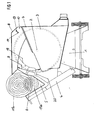
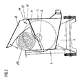
- FIG. 1 and 2 constructed according to the Wippsägenkar firewood circular saw includes a mobile machine frame 1, which is expediently constructed in the manner of a truncated pyramid.
- a shaft 2 is mounted, which cooperates on the one hand with a drive motor, not shown, and on the other hand carries a machine frame on one side flanking saw blade 3.
- a receiving channel for sawing exhibiting feed member is provided at the front of the machine frame 1 a relative to the stationary saw blade 3 movable.
- This is formed in the example shown as an axis parallel to the saw blade axis pivotable rocker 4, which has a receiving channel 5 for the pole containing, in cross-section v-shaped receiving piece 6.
- the saw blade 3 is associated with a mounted on the adjacent side edge of the machine frame 1 protective housing. This consists of a lower portion of the saw blade 3 receiving lower part 7 and a cross over this, an upper portion of the saw blade 3 associated Upper part 8.
- the upper edge of the lower part 7 is rising from front to rear.
- the lower edge of the upper part 8 is sloping from front to back.
- a working gap 9 opening towards the advancing member is limited.
- the clear input width of the working gap 9 limits the permissible thickness of the workable shegguts.
- the upper part 8 is pivotable about an axis parallel to the saw blade axis 10 from a lower, the figure 1 underlying stop position in an upper, the figure 2 underlying stop position.
- the upward pivoting movement is expediently counter to the force of a restoring device, which automatically returns the upper part 8 to the lower stop position.
- woods with a normal diameter of the type indicated at 11a in FIG. 1 can be cut.
- Firewood batches may, however, also include woods with a much larger diameter of the kind indicated in FIG. 1 at 11 b.
- the pivot axis 10 of the upper part 8 is located in the rear, that is in the area of the protective housing remote from the entrance of the working gap 9.
- the lateral guide plates 12 provided in the rear of the protective housing with its upper edge überrag-, which are expediently formed as flat sheets, which bear against the opposite inner sides of the lower part 7 forming box and are connected to the box side walls. The rear edge of said tabs may rest against the rear wall of the box.
- the upper part 8 is expediently designed as a downwardly open, in cross-section U-shaped box, in which the guide plates 12 engage. These lie on the box inside, so that there is a reliable, lateral guidance.
- a lateral guide tabs 12 bridging, indicated in Figure 4 bolt 10a is provided, which projects beyond the lateral guide tabs 12 and engages in associated, visible in Figure 4 above holes 10b of the upper part 8 forming box.
- At least one, preferably both of the bolts 10a carrying guide plates 12 are, as shown in Figure 4 further below, provided with a pin axis to the axis and thus to the pivot axis of the upper part 8 concentric arcuate slot 13.
- the upper part 8 contains the curved slot 13 of a guide plate 12 in the example shown, the aligned arcuate slots 13 both guide plates 12 associated, laterally projecting, indicated in Figure 4 above pin 14, which engage in the respective adjacent arch slot 13.
- the upper part 8 may be provided with a side projecting pin bridging its lateral walls.
- Each of the engaging in an arcuate slot 13 pin 14 acts as a stop member, which starts to limit the pivot angle of the upper part 8 at the ends of the associated arcuate slot 13. In the lower position, the stops are at the lower end, in the upper position at the upper end of the associated curved slot 13.
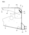
- a spring 15 shown in FIG. 3 is provided in the example illustrated. This is formed in the example shown as a tension spring, the upper end of the upper part 8 and the lower end of the lower part 7 attack.
- the upper end of the spring 15 may suitably engage the abovementioned pin 14a provided for forming the pins 14.
- the lower end of the spring 15 can engage a pin 16 bridging the guide tabs 12 or side walls of the lower part 7.
- the restoring device can also be formed by a spring arrangement containing a plurality of springs. The use of other types of springs, such as a bow spring, etc. would be conceivable.
- the bearing remote end of the upper part 8 is useful as formed with the lower edge of the upper part 8 an obtuse angle forming run-on slope 17.
- Thicker blanks of the type indicated at 11 b in Figure 1 run, as shown in Figure 1 can be seen on the run-on slope 17, whereby the upper part 8 is raised.
- the adjoining the run-on slope 17 lower edge 18 of the upper part 8 is formed concave with respect to the axis of the saw blade 3. This facilitates the sliding of the upper part 8 on a piece of wood which presses it up, as can be clearly seen from FIG.
- the recording channel 5 containing, in cross-section v-shaped receiving piece 6 is provided with a saw blade 3 associated slot into which the saw blade 3 can dive to make a cut.
- the saw blade 3 is also protected in the region of the working gap 9 in such a way that no engagement is possible from the side.
- the receiving piece 6 is flanking with the above-mentioned slot, best seen in Figure 1 visible Abdeckschilden 19 which engage in the lower part 7 and upper part 8 forming, respectively U-shaped box.
- the cover plates 19 are provided with recesses associated with the shaft 2 or the saw blade attachment.
- the receiving piece 6 is provided with covers 20 which are laterally offset with respect to the recesses mentioned and which laterally flank the lower part 7 in the lowest engagement position, as can be seen from FIG.
- the lower part 7 is provided in the region of the lower rear corner with an ejection opening 21 provided here in the lower region of the narrow rear wall, via which the airflow generated by the saw blade 3 can emerge and sawdust can be ejected.
- the outlet opening 21 may open into the environment or into an associated disposal facility.
- the ejection opening 21 is associated with a fixed to the lower part 7 connector 22 having a connection piece 23 for connecting a suction hose or a like a filter basket or the like. Trapped container. Of course, it would also be conceivable to connect such a collecting container directly to the lower part 7.
Landscapes
- Life Sciences & Earth Sciences (AREA)
- Engineering & Computer Science (AREA)
- Mechanical Engineering (AREA)
- Wood Science & Technology (AREA)
- Forests & Forestry (AREA)
- Sawing (AREA)
- Processing Of Meat And Fish (AREA)
- Debarking, Splitting, And Disintegration Of Timber (AREA)
Applications Claiming Priority (1)
| Application Number | Priority Date | Filing Date | Title |
|---|---|---|---|
| DE202006010777U DE202006010777U1 (de) | 2006-07-11 | 2006-07-11 | Brennholzkreissäge |
Publications (2)
| Publication Number | Publication Date |
|---|---|
| EP1878548A1 true EP1878548A1 (fr) | 2008-01-16 |
| EP1878548B1 EP1878548B1 (fr) | 2011-09-28 |
Family
ID=37085590
Family Applications (1)
| Application Number | Title | Priority Date | Filing Date |
|---|---|---|---|
| EP07013343A Not-in-force EP1878548B1 (fr) | 2006-07-11 | 2007-07-07 | Scie circulaire pour bois de chauffage |
Country Status (4)
| Country | Link |
|---|---|
| EP (1) | EP1878548B1 (fr) |
| CN (1) | CN101104280B (fr) |
| AT (1) | ATE526131T1 (fr) |
| DE (1) | DE202006010777U1 (fr) |
Families Citing this family (7)
| Publication number | Priority date | Publication date | Assignee | Title |
|---|---|---|---|---|
| DE102008010886A1 (de) * | 2008-02-25 | 2009-09-10 | Scheppach Fabrikation Von Holzbearbeitungsmaschinen Gmbh | Brennholzkappsäge |
| DE102008055934B4 (de) * | 2008-11-05 | 2016-05-25 | Scheppach Fabrikation Von Holzbearbeitungsmaschinen Gmbh | Brennholzkappsäge |
| DE102008012955B4 (de) * | 2008-03-06 | 2012-06-28 | Ferdinand Wagner | Sägegutauflage und Säge umfassend eine solche Sägegutauflage |
| DE202010011450U1 (de) | 2010-05-26 | 2010-12-30 | Scheppach Fabrikation Von Holzbearbeitungsmaschinen Gmbh | Wippkreissäge |
| DE102010021523B4 (de) | 2010-05-26 | 2020-07-30 | Scheppach Fabrikation Von Holzbearbeitungsmaschinen Gmbh | Wippkreissäge |
| DE202012007421U1 (de) * | 2012-08-03 | 2013-11-04 | Südharzer Maschinenbau GmbH | Vorrichtung zum Bearbeiten von Holzstücken |
| AT521147B1 (de) * | 2018-06-29 | 2019-11-15 | Posch Gmbh | Verschiebbare Schutzverkleidung |
Citations (2)
| Publication number | Priority date | Publication date | Assignee | Title |
|---|---|---|---|---|
| FR987029A (fr) | 1949-02-28 | 1951-08-08 | Dispositif de sécurité notamment applicable aux scies à bûches à chevalet | |
| EP0071902A2 (fr) | 1981-08-07 | 1983-02-16 | Alois Kober KG, Maschinenfabrik | Machine-outil pour bricoleur, notamment scie circulaire basculante avec porte-pièce |
Family Cites Families (1)
| Publication number | Priority date | Publication date | Assignee | Title |
|---|---|---|---|---|
| CN2495431Y (zh) * | 2001-09-20 | 2002-06-19 | 圣杰机器工业股份有限公司 | 一种具有改良工作台的圆锯机 |
-
2006
- 2006-07-11 DE DE202006010777U patent/DE202006010777U1/de not_active Expired - Lifetime
-
2007
- 2007-07-07 EP EP07013343A patent/EP1878548B1/fr not_active Not-in-force
- 2007-07-07 AT AT07013343T patent/ATE526131T1/de active
- 2007-07-11 CN CN2007101290514A patent/CN101104280B/zh not_active Expired - Fee Related
Patent Citations (2)
| Publication number | Priority date | Publication date | Assignee | Title |
|---|---|---|---|---|
| FR987029A (fr) | 1949-02-28 | 1951-08-08 | Dispositif de sécurité notamment applicable aux scies à bûches à chevalet | |
| EP0071902A2 (fr) | 1981-08-07 | 1983-02-16 | Alois Kober KG, Maschinenfabrik | Machine-outil pour bricoleur, notamment scie circulaire basculante avec porte-pièce |
Also Published As
| Publication number | Publication date |
|---|---|
| CN101104280A (zh) | 2008-01-16 |
| CN101104280B (zh) | 2012-04-04 |
| EP1878548B1 (fr) | 2011-09-28 |
| DE202006010777U1 (de) | 2006-09-28 |
| ATE526131T1 (de) | 2011-10-15 |
Similar Documents
| Publication | Publication Date | Title |
|---|---|---|
| EP1878548B1 (fr) | Scie circulaire pour bois de chauffage | |
| EP0956932B1 (fr) | Dispositif pour couper des pièces allongées | |
| EP1837147A1 (fr) | Fendeur de bois | |
| DE1552633A1 (de) | Vorrichtung zum Beschneiden mindestens einer Kante eines Blechbandes | |
| DE3733412A1 (de) | Papierzufuehreinrichtung und damit ausgeruesteter aktenvernichter | |
| DE102019109712B3 (de) | Vorrichtung und Verfahren zum Schneiden eines Lebensmittels in Streifen oder Würfel | |
| DE69716995T2 (de) | Elektroheftgerät | |
| EP2390070B1 (fr) | Scie pour couper du bois de chauffage | |
| EP2386391B1 (fr) | Fendeur de bois doté d'une surface de transport et d'une surface de stabilisation se déroulant dans l'intervalle de fente pour fendre des bûches de bois à partir d'un tronc | |
| DE102005032714A1 (de) | Schneidemaschine für Lebensmittel, insbesondere für Brot | |
| DE3044395A1 (de) | Fleisch- und knochenbandsaege | |
| EP2390071B1 (fr) | Scie circulaire à bascule | |
| DE3440523A1 (de) | Schneidvorrichtung | |
| DE102004049699B4 (de) | Vorrichtung zum Sägen von langgestrecktem Sägegut | |
| EP2119538A1 (fr) | Dispositif de coupe de bois selon une coupe multiple | |
| AT501975B1 (de) | Feststehendes messer für eine hackmaschine | |
| EP2357053B1 (fr) | Guidage de lime | |
| EP1716955B1 (fr) | Dispositif de sciage avec un dispositif de blocage | |
| EP2589472B1 (fr) | Scie à bascule | |
| DE2707030C2 (de) | Schneidwerk für Mähvorrichtungen | |
| DE3013375A1 (de) | Vorrichtung zum zerkleinern von holz | |
| DE2552840A1 (de) | Zerspanmaschine | |
| DE202010011450U1 (de) | Wippkreissäge | |
| DE3303280A1 (de) | Vorrichtung zum abtrennen der schwarte oder haut von fleisch oder speck | |
| DE2850294A1 (de) | Maschine zum schneiden und haeckseln von pflanzen |
Legal Events
| Date | Code | Title | Description |
|---|---|---|---|
| PUAI | Public reference made under article 153(3) epc to a published international application that has entered the european phase |
Free format text: ORIGINAL CODE: 0009012 |
|
| AK | Designated contracting states |
Kind code of ref document: A1 Designated state(s): AT BE BG CH CY CZ DE DK EE ES FI FR GB GR HU IE IS IT LI LT LU LV MC MT NL PL PT RO SE SI SK TR |
|
| AX | Request for extension of the european patent |
Extension state: AL BA HR MK YU |
|
| 17P | Request for examination filed |
Effective date: 20080325 |
|
| AKX | Designation fees paid |
Designated state(s): AT CH DE LI |
|
| 17Q | First examination report despatched |
Effective date: 20100319 |
|
| GRAP | Despatch of communication of intention to grant a patent |
Free format text: ORIGINAL CODE: EPIDOSNIGR1 |
|
| GRAS | Grant fee paid |
Free format text: ORIGINAL CODE: EPIDOSNIGR3 |
|
| GRAA | (expected) grant |
Free format text: ORIGINAL CODE: 0009210 |
|
| AK | Designated contracting states |
Kind code of ref document: B1 Designated state(s): AT CH DE LI |
|
| REG | Reference to a national code |
Ref country code: CH Ref legal event code: EP |
|
| REG | Reference to a national code |
Ref country code: DE Ref legal event code: R096 Ref document number: 502007008240 Country of ref document: DE Effective date: 20111124 |
|
| PLBE | No opposition filed within time limit |
Free format text: ORIGINAL CODE: 0009261 |
|
| STAA | Information on the status of an ep patent application or granted ep patent |
Free format text: STATUS: NO OPPOSITION FILED WITHIN TIME LIMIT |
|
| 26N | No opposition filed |
Effective date: 20120629 |
|
| REG | Reference to a national code |
Ref country code: DE Ref legal event code: R097 Ref document number: 502007008240 Country of ref document: DE Effective date: 20120629 |
|
| PGFP | Annual fee paid to national office [announced via postgrant information from national office to epo] |
Ref country code: CH Payment date: 20140722 Year of fee payment: 8 Ref country code: DE Payment date: 20140731 Year of fee payment: 8 |
|
| PGFP | Annual fee paid to national office [announced via postgrant information from national office to epo] |
Ref country code: AT Payment date: 20140620 Year of fee payment: 8 |
|
| REG | Reference to a national code |
Ref country code: DE Ref legal event code: R119 Ref document number: 502007008240 Country of ref document: DE |
|
| REG | Reference to a national code |
Ref country code: CH Ref legal event code: PL |
|
| REG | Reference to a national code |
Ref country code: AT Ref legal event code: MM01 Ref document number: 526131 Country of ref document: AT Kind code of ref document: T Effective date: 20150707 |
|
| PG25 | Lapsed in a contracting state [announced via postgrant information from national office to epo] |
Ref country code: LI Free format text: LAPSE BECAUSE OF NON-PAYMENT OF DUE FEES Effective date: 20150731 Ref country code: CH Free format text: LAPSE BECAUSE OF NON-PAYMENT OF DUE FEES Effective date: 20150731 Ref country code: DE Free format text: LAPSE BECAUSE OF NON-PAYMENT OF DUE FEES Effective date: 20160202 |
|
| PG25 | Lapsed in a contracting state [announced via postgrant information from national office to epo] |
Ref country code: AT Free format text: LAPSE BECAUSE OF NON-PAYMENT OF DUE FEES Effective date: 20150707 |