EP1878569A2 - Dispositif pour supporter le guidage des feuilles dans des machines d'impression - Google Patents
Dispositif pour supporter le guidage des feuilles dans des machines d'impression Download PDFInfo
- Publication number
- EP1878569A2 EP1878569A2 EP07112412A EP07112412A EP1878569A2 EP 1878569 A2 EP1878569 A2 EP 1878569A2 EP 07112412 A EP07112412 A EP 07112412A EP 07112412 A EP07112412 A EP 07112412A EP 1878569 A2 EP1878569 A2 EP 1878569A2
- Authority
- EP
- European Patent Office
- Prior art keywords
- sheet
- cylinder
- bogenabstreifeinrichtung
- bogenabstreifelement
- traction means
- Prior art date
- Legal status (The legal status is an assumption and is not a legal conclusion. Google has not performed a legal analysis and makes no representation as to the accuracy of the status listed.)
- Granted
Links
Images


Classifications
-
- B—PERFORMING OPERATIONS; TRANSPORTING
- B41—PRINTING; LINING MACHINES; TYPEWRITERS; STAMPS
- B41F—PRINTING MACHINES OR PRESSES
- B41F21/00—Devices for conveying sheets through printing apparatus or machines
-
- B—PERFORMING OPERATIONS; TRANSPORTING
- B41—PRINTING; LINING MACHINES; TYPEWRITERS; STAMPS
- B41F—PRINTING MACHINES OR PRESSES
- B41F21/00—Devices for conveying sheets through printing apparatus or machines
- B41F21/10—Combinations of transfer drums and grippers
- B41F21/106—Combinations of transfer drums and grippers for reversing sheets, e.g. for perfecting machine
- B41F21/108—Combinations of transfer drums and grippers for reversing sheets, e.g. for perfecting machine with pneumatic means
Definitions
- the invention relates to a device for supporting the sheet guide in printing presses, which can be used either in straight printing or perfecting and with which the sheet can be turned in the perfecting method according to the principle of trailing edge application, wherein the on a cylinder with grippers guided sheet is detected and continued by a sheet transfer system of a turning drum.
- the feed level e.g. the surface of the storage drum (three-drum turn) or the surface of the printing cylinder (single-drum turn) or the surface of a Leitrakel (also single-drum turn)
- the following sheet is through the storage drum, impression cylinder or paradox of the Leitrakel itself and the one-stroke advancing, from the reversal of motion opposite moving turn arc brought by the inertia effect and aerodynamic forces of the rotating drum body and the paradox on the Leitrakel.
- Another reason for the sheet encounter in the feed level is the use of air cushions against the greasing on the underside of the arch. The force acting in the direction of the turning arc of the air cushion can lead to pressing the turning arc to the next in the feed plane and thus for greasing between the two sheets.
- a sheet guiding device in which the subsequent and the withdrawing sheet are separated from each other by mechanical means by the withdrawing sheet is pressed after its reversal by a rake from the feed plane of the Leitrakel in the effective range of the baffle.
- the withdrawing sheet is directed at the leading edge, which has now become the trailing edge of the sheet, by means of a rake.
- the length of the rake is limited by the condition that the foremost point of the rake must have taken the starting position behind the feeding plane of the sheet before the arrival of the subsequent sheet. Again, the leadership of the subtending bow is not enough to displace the volume of air from the forming bow wave and avoid contact of the turned with the following arc safely.
- the object is achieved by a device having the features of the first claim.
- the invention has the advantage that the turned sheet is pressed out of the path of the following sheet in the direction of the sheet withdrawal plane by the sheet stripping device.
- a suction device is provided on the sheet wiper, with which the turned arc is temporarily sucked. This streamlines this bow.
- the volume of air under the sheet to be turned is displaced, so that the formation of a bow wave is largely avoided.
- the streamed away from the Leitrakel, streamlined bow is kept away from the action of the blow-suction air from the Leitrakler.
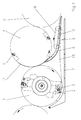
- a pressure cylinder 4 which in turn is a sheet guiding cylinder 5 downstream.
- the direction of rotation of the cylinders is indicated by directional arrows.
- the Leitrakel 6 is disposed over the width of the printing cylinder 4 and it is associated with the front part at a small distance from the periphery of the printing cylinder 4.
- a baffle 7 is provided below the Leitrakel 6 at a distance from this. The baffle 7 has holes through which the turned-off sheet can be pneumatically acted upon.
- the Bogenabstreif driving 8 consists of a circulating belt 9 on which a wedge-shaped Bogenabstreifelement 10 is arranged.
- the drive of the belt 9 is not shown.
- the sheet stripping device 8 can be lowered directly below the cylinder 4 in the gripper channel and intermittently below the cylinder surface.
- the control of Bogenabstreif sexual 8 is effected by a cam gear 15.
- the cam gear 15 is associated with a fixed curve on the machine frame.
- a plurality of shafts are provided which are spaced apart from one another and on which disk segments 14 serving as bow scraping elements 10 are provided are provided.
- the disk segments 14 are driven by the traction means 9 rotating in the direction of movement of the sheet 12 to be turned.
- a further embodiment of the variant of the assignment of Bogenabstreifetti 10 is shown to a plurality of rotating shafts, which are driven by a traction means 9.
- the Bogenabstreifimplantation 10 are connected in parallel here via a parallel crank mechanism 18 with two shafts.
- the bow to be turned 12 is applied in the operating mode perfecting on the printing cylinder 4 of the recto printing. Thereafter, the sheet 12 to be reversed passes through the tangent point of the printing cylinder 4 and turning drum 1, where the sheet 12 to be turned sucked in the rear of the suction system 2, guided under the periphery of the turning drum 1, passed to the gripper system 3 and turned to the following pressure cylinder, not shown is supplied, where the counterpressure takes place.
- the sheet 12 to be turned is held by the gripper 11 of the printing cylinder 4.
- the gripper 11 opens shortly before reaching the Leitrakel 6, the sheet to be turned 12 is released with its leading edge from the printing cylinder 4 in a known manner and guided along the Leitrakel 6.
- the system of the sheet 12 to be turned on the Leitrakel 6 can be supported by emerging from blowing nozzles, between Leitrakel 6 and 12 to be turned arc blown air.
- the wedge-shaped sheet scraping element 10 pivots in its orbit in front of the leading edge of the following sheet 12 to be deflected into the doctor blade plane and is transported in the sheet conveying direction with sheet speed to the sheet reversal point and constantly presses the turned arc 13 from the area of the Leitrakel 6 in the effective range of the baffle. 7
- the Bogenabstreifelement 10 is moved by the rotation of the cylinder 4 in front of the leading edge of the subsequent sheet to be turned 12. Since the Bogenabstreifelement 10 is in the passage of the turning drum 1 whose cap opposite and thus can collide with her, it is necessary at least in this moment the Bogenabstreifelement 10 lower below the periphery of the cylinder 4.
Landscapes
- Feeding Of Articles By Means Other Than Belts Or Rollers (AREA)
- Discharge By Other Means (AREA)
Applications Claiming Priority (1)
| Application Number | Priority Date | Filing Date | Title |
|---|---|---|---|
| DE200610032922 DE102006032922B3 (de) | 2006-07-15 | 2006-07-15 | Einrichtung zur Unterstützung der Bogenführung in Druckmaschinen |
Publications (3)
| Publication Number | Publication Date |
|---|---|
| EP1878569A2 true EP1878569A2 (fr) | 2008-01-16 |
| EP1878569A3 EP1878569A3 (fr) | 2008-09-17 |
| EP1878569B1 EP1878569B1 (fr) | 2010-10-13 |
Family
ID=38438645
Family Applications (1)
| Application Number | Title | Priority Date | Filing Date |
|---|---|---|---|
| EP20070112412 Ceased EP1878569B1 (fr) | 2006-07-15 | 2007-07-13 | Dispositif pour supporter le guidage des feuilles dans des machines d'impression |
Country Status (2)
| Country | Link |
|---|---|
| EP (1) | EP1878569B1 (fr) |
| DE (2) | DE102006032922B3 (fr) |
Families Citing this family (9)
| Publication number | Priority date | Publication date | Assignee | Title |
|---|---|---|---|---|
| DE102008051093B4 (de) | 2008-10-09 | 2021-10-21 | Heidelberger Druckmaschinen Ag | Vorrichtung zum Umstülpen eines Bogens um eine Querachse während eines Förderns zwischen zwei Druckwerken einer Druckmaschine |
| DE102015209689B4 (de) | 2014-06-18 | 2021-03-25 | Koenig & Bauer Ag | Wendevorrichtung für eine bogenverarbeitende Maschine und Verfahren zum Wenden von Bogen |
| DE102015209690C5 (de) | 2014-06-18 | 2025-08-21 | Koenig & Bauer Ag | Wendevorrichtung und Verfahren zum Wenden von Bogen |
| DE102015209687B4 (de) | 2014-06-18 | 2020-07-02 | Koenig & Bauer Ag | Wendevorrichtung und Verfahren zum Wenden von Bogen |
| DE102015209700B4 (de) | 2015-05-27 | 2018-06-07 | Koenig & Bauer Ag | Bogenführungszylinder und Verfahren zum Fördern eines Bogens in einer bogenverarbeitenden Maschine |
| DE102015209699B4 (de) * | 2015-05-27 | 2018-06-07 | Koenig & Bauer Ag | Wendevorrichtung und Verfahren zum Wenden eines Bogens mit einem Bogenführungszylinder und einer an den Bogenführungszylinder angestellten Ablöseeinrichtung |
| DE102015209697B4 (de) | 2015-05-27 | 2018-04-05 | Koenig & Bauer Ag | Bogenführungszylinder und Verfahren zum Fördern eines Bogens in einer bogenverarbeitenden Maschine |
| DE102018215386A1 (de) | 2017-10-06 | 2019-04-11 | Heidelberger Druckmaschinen Ag | Druckmaschine mit einer Wendeeinrichtung und einer Leiteinrichtung |
| DE102024103991A1 (de) * | 2024-02-13 | 2025-08-14 | Koenig & Bauer Ag | Bogentransporttrommel und Verfahren zum Betreiben einer bogenverarbeitenden Maschine mit einer Bogentransporttrommel |
Citations (2)
| Publication number | Priority date | Publication date | Assignee | Title |
|---|---|---|---|---|
| DE4424970A1 (de) | 1994-07-15 | 1996-01-18 | Kba Planeta Ag | Pneumatisch arbeitende Leiteinrichtung zum Wenden von Bogen |
| DE4424971A1 (de) | 1994-07-15 | 1996-01-18 | Kba Planeta Ag | Leiteinrichtung an Bogenrotationsdruckmaschinen |
Family Cites Families (10)
| Publication number | Priority date | Publication date | Assignee | Title |
|---|---|---|---|---|
| DD101336A1 (fr) * | 1972-12-27 | 1973-11-12 | ||
| DE2724621A1 (de) * | 1977-06-01 | 1978-12-14 | Maschf Augsburg Nuernberg Ag | Bogenwendevorrichtung einer bogen- rotations-druckmaschine in reihenbauart |
| DE4030070C2 (de) * | 1990-09-22 | 1997-04-17 | Kba Planeta Ag | Bogenspeichereinheit an Rotationsdruckmaschinen |
| DE4210327A1 (de) * | 1992-03-30 | 1993-10-07 | Koenig & Bauer Ag | Bogenwendeeinrichtung in einer Rotationsdruckmaschine |
| DE4424977C2 (de) * | 1994-07-15 | 2000-08-10 | Koenig & Bauer Ag | Bogenabweiser |
| DE9411462U1 (de) * | 1994-07-15 | 1994-09-08 | Kba-Planeta Ag, 01445 Radebeul | Blaseinrichtung zur Unterstützung der Bogenführung |
| DE4424968C2 (de) * | 1994-07-15 | 1997-12-11 | Kba Planeta Ag | Verfahren und Einrichtung zur Bogenführung und Bogenleitung beim Wendevorgang |
| DE4424972C2 (de) * | 1994-07-15 | 1998-03-19 | Kba Planeta Ag | Einrichtung an bogenführenden Zylindern |
| DE19940214B4 (de) * | 1998-03-28 | 2014-03-06 | Koenig & Bauer Aktiengesellschaft | Leitrakel zur Bogenführung in Druckmaschinen |
| DE10152875B4 (de) * | 2000-11-21 | 2014-08-07 | Heidelberger Druckmaschinen Ag | Wendeeinrichtung mit Speicher für flächiges Material |
-
2006
- 2006-07-15 DE DE200610032922 patent/DE102006032922B3/de not_active Expired - Fee Related
-
2007
- 2007-07-13 EP EP20070112412 patent/EP1878569B1/fr not_active Ceased
- 2007-07-13 DE DE200750005317 patent/DE502007005317D1/de active Active
Patent Citations (2)
| Publication number | Priority date | Publication date | Assignee | Title |
|---|---|---|---|---|
| DE4424970A1 (de) | 1994-07-15 | 1996-01-18 | Kba Planeta Ag | Pneumatisch arbeitende Leiteinrichtung zum Wenden von Bogen |
| DE4424971A1 (de) | 1994-07-15 | 1996-01-18 | Kba Planeta Ag | Leiteinrichtung an Bogenrotationsdruckmaschinen |
Also Published As
| Publication number | Publication date |
|---|---|
| EP1878569A3 (fr) | 2008-09-17 |
| DE102006032922B3 (de) | 2007-09-27 |
| DE502007005317D1 (de) | 2010-11-25 |
| EP1878569B1 (fr) | 2010-10-13 |
Similar Documents
| Publication | Publication Date | Title |
|---|---|---|
| EP1878569B1 (fr) | Dispositif pour supporter le guidage des feuilles dans des machines d'impression | |
| DE102015209695B4 (de) | Bogenführungszylinder und Verfahren zur Formatverstellung eines Bogenführungszylinders | |
| EP3224049B1 (fr) | Machine de traitement de feuilles avec un tambour de guidage de feuilles comportant un système de pinces et procédé de fabrication d'un système de pinces | |
| EP0000011B2 (fr) | Machine rotative pour imprimer des feuilles. | |
| DE102015226325B4 (de) | Bogenverarbeitende Maschine mit einem einer Doppelgreiferauslage vorgeordneten Bogenführungszylinder und Verfahren zum Ablegen von Bogen | |
| DE2756507A1 (de) | Verfahren und vorrichtung zum wenden eines bogens in einer bogendruckmaschine, buchbindemaschine o.dgl. | |
| DE19940214B4 (de) | Leitrakel zur Bogenführung in Druckmaschinen | |
| DE102015209700B4 (de) | Bogenführungszylinder und Verfahren zum Fördern eines Bogens in einer bogenverarbeitenden Maschine | |
| EP1864799B1 (fr) | Dispositif destiné à la conduite de feuilles dans des machines d'impression | |
| EP0257366A2 (fr) | Dispositif pour marger en position correcte une feuille sur la table de marge d'une presse rotative | |
| DE19814320C1 (de) | Verfahren und Vorrichtung zum Wenden eines Bogens in einer Druckmaschine | |
| DE102008051094B4 (de) | Vorrichtung zum Umstülpen eines Bogens um eine Querachse während eines Förderns zwischen zwei Druckwerken einer Druckmaschine | |
| DE102015209697B4 (de) | Bogenführungszylinder und Verfahren zum Fördern eines Bogens in einer bogenverarbeitenden Maschine | |
| DE102009001189A1 (de) | Auslagevorrichtung einer bogenverarbeitenden Maschine mit einem Bogenfördersystem zum Fördern der Bogen | |
| DE102015209687B4 (de) | Wendevorrichtung und Verfahren zum Wenden von Bogen | |
| DE102006032924B3 (de) | Bogenleiteinrichtung an Rotationsdruckmaschinen | |
| DE102011011119A1 (de) | Vorrichtung zum Wenden eines Bogens während des Förderns durch eine Druckmaschine | |
| DE102008051095B4 (de) | Bogendruckmaschine mit einer Reihenanordnung von Druckwerken | |
| DE4230568C2 (de) | Vorgreifer | |
| DE102006032923B3 (de) | Leiteinrichtung an Bogenrotationsdruckmaschinen | |
| DE102015209699B4 (de) | Wendevorrichtung und Verfahren zum Wenden eines Bogens mit einem Bogenführungszylinder und einer an den Bogenführungszylinder angestellten Ablöseeinrichtung | |
| DE102014116009A1 (de) | Überformatwendung | |
| DE102024103991A1 (de) | Bogentransporttrommel und Verfahren zum Betreiben einer bogenverarbeitenden Maschine mit einer Bogentransporttrommel | |
| DE102015226330B4 (de) | Auslage für eine bogenverarbeitende Maschine | |
| DE102015204556B4 (de) | Bogengreifersystem |
Legal Events
| Date | Code | Title | Description |
|---|---|---|---|
| PUAI | Public reference made under article 153(3) epc to a published international application that has entered the european phase |
Free format text: ORIGINAL CODE: 0009012 |
|
| AK | Designated contracting states |
Kind code of ref document: A2 Designated state(s): AT BE BG CH CY CZ DE DK EE ES FI FR GB GR HU IE IS IT LI LT LU LV MC MT NL PL PT RO SE SI SK TR |
|
| AX | Request for extension of the european patent |
Extension state: AL BA HR MK YU |
|
| PUAL | Search report despatched |
Free format text: ORIGINAL CODE: 0009013 |
|
| AK | Designated contracting states |
Kind code of ref document: A3 Designated state(s): AT BE BG CH CY CZ DE DK EE ES FI FR GB GR HU IE IS IT LI LT LU LV MC MT NL PL PT RO SE SI SK TR |
|
| AX | Request for extension of the european patent |
Extension state: AL BA HR MK RS |
|
| 17P | Request for examination filed |
Effective date: 20080904 |
|
| AKX | Designation fees paid |
Designated state(s): DE FR GB IT |
|
| GRAP | Despatch of communication of intention to grant a patent |
Free format text: ORIGINAL CODE: EPIDOSNIGR1 |
|
| GRAC | Information related to communication of intention to grant a patent modified |
Free format text: ORIGINAL CODE: EPIDOSCIGR1 |
|
| GRAS | Grant fee paid |
Free format text: ORIGINAL CODE: EPIDOSNIGR3 |
|
| GRAA | (expected) grant |
Free format text: ORIGINAL CODE: 0009210 |
|
| AK | Designated contracting states |
Kind code of ref document: B1 Designated state(s): DE FR GB IT |
|
| REG | Reference to a national code |
Ref country code: GB Ref legal event code: FG4D Free format text: NOT ENGLISH |
|
| REF | Corresponds to: |
Ref document number: 502007005317 Country of ref document: DE Date of ref document: 20101125 Kind code of ref document: P |
|
| RAP2 | Party data changed (patent owner data changed or rights of a patent transferred) |
Owner name: KOENIG & BAUER AKTIENGESELLSCHAFT |
|
| PLBE | No opposition filed within time limit |
Free format text: ORIGINAL CODE: 0009261 |
|
| STAA | Information on the status of an ep patent application or granted ep patent |
Free format text: STATUS: NO OPPOSITION FILED WITHIN TIME LIMIT |
|
| 26N | No opposition filed |
Effective date: 20110714 |
|
| REG | Reference to a national code |
Ref country code: DE Ref legal event code: R097 Ref document number: 502007005317 Country of ref document: DE Effective date: 20110714 |
|
| REG | Reference to a national code |
Ref country code: DE Ref legal event code: R081 Ref document number: 502007005317 Country of ref document: DE Owner name: KOENIG BAUER AG, DE Free format text: FORMER OWNER: KOENIG BAUER AKTIENGESELLSCHAFT, 97080 WUERZBURG, DE Ref country code: DE Ref legal event code: R081 Ref document number: 502007005317 Country of ref document: DE Owner name: KOENIG & BAUER AG, DE Free format text: FORMER OWNER: KOENIG & BAUER AKTIENGESELLSCHAFT, 97080 WUERZBURG, DE |
|
| REG | Reference to a national code |
Ref country code: FR Ref legal event code: PLFP Year of fee payment: 10 |
|
| REG | Reference to a national code |
Ref country code: FR Ref legal event code: PLFP Year of fee payment: 11 |
|
| REG | Reference to a national code |
Ref country code: FR Ref legal event code: PLFP Year of fee payment: 12 |
|
| PGFP | Annual fee paid to national office [announced via postgrant information from national office to epo] |
Ref country code: IT Payment date: 20190731 Year of fee payment: 13 Ref country code: FR Payment date: 20190725 Year of fee payment: 13 |
|
| PGFP | Annual fee paid to national office [announced via postgrant information from national office to epo] |
Ref country code: GB Payment date: 20190724 Year of fee payment: 13 |
|
| GBPC | Gb: european patent ceased through non-payment of renewal fee |
Effective date: 20200713 |
|
| PG25 | Lapsed in a contracting state [announced via postgrant information from national office to epo] |
Ref country code: GB Free format text: LAPSE BECAUSE OF NON-PAYMENT OF DUE FEES Effective date: 20200713 Ref country code: FR Free format text: LAPSE BECAUSE OF NON-PAYMENT OF DUE FEES Effective date: 20200731 |
|
| PG25 | Lapsed in a contracting state [announced via postgrant information from national office to epo] |
Ref country code: IT Free format text: LAPSE BECAUSE OF NON-PAYMENT OF DUE FEES Effective date: 20200713 |
|
| PGFP | Annual fee paid to national office [announced via postgrant information from national office to epo] |
Ref country code: DE Payment date: 20240903 Year of fee payment: 18 |
|
| REG | Reference to a national code |
Ref country code: DE Ref legal event code: R119 Ref document number: 502007005317 Country of ref document: DE |
|
| PG25 | Lapsed in a contracting state [announced via postgrant information from national office to epo] |
Ref country code: DE Free format text: LAPSE BECAUSE OF NON-PAYMENT OF DUE FEES Effective date: 20260203 |