EP1878956A1 - Valve device - Google Patents
Valve device Download PDFInfo
- Publication number
- EP1878956A1 EP1878956A1 EP06731461A EP06731461A EP1878956A1 EP 1878956 A1 EP1878956 A1 EP 1878956A1 EP 06731461 A EP06731461 A EP 06731461A EP 06731461 A EP06731461 A EP 06731461A EP 1878956 A1 EP1878956 A1 EP 1878956A1
- Authority
- EP
- European Patent Office
- Prior art keywords
- valve
- valve plates
- plates
- seats
- closing
- Prior art date
- Legal status (The legal status is an assumption and is not a legal conclusion. Google has not performed a legal analysis and makes no representation as to the accuracy of the status listed.)
- Granted
Links
- 238000005096 rolling process Methods 0.000 claims description 12
- 230000002411 adverse Effects 0.000 abstract description 2
- 238000009434 installation Methods 0.000 abstract 1
- 230000033001 locomotion Effects 0.000 description 31
- 239000002344 surface layer Substances 0.000 description 5
- 230000007246 mechanism Effects 0.000 description 4
- 230000004048 modification Effects 0.000 description 3
- 238000012986 modification Methods 0.000 description 3
- 230000000694 effects Effects 0.000 description 2
- 239000012530 fluid Substances 0.000 description 2
- 238000000034 method Methods 0.000 description 2
- 238000004381 surface treatment Methods 0.000 description 2
- 230000000903 blocking effect Effects 0.000 description 1
- 230000006835 compression Effects 0.000 description 1
- 238000007906 compression Methods 0.000 description 1
- 238000010276 construction Methods 0.000 description 1
- 238000010586 diagram Methods 0.000 description 1
- 230000006872 improvement Effects 0.000 description 1
- 230000001939 inductive effect Effects 0.000 description 1
- 238000004519 manufacturing process Methods 0.000 description 1
- 230000008569 process Effects 0.000 description 1
- 238000007789 sealing Methods 0.000 description 1
Images


Classifications
-
- F—MECHANICAL ENGINEERING; LIGHTING; HEATING; WEAPONS; BLASTING
- F16—ENGINEERING ELEMENTS AND UNITS; GENERAL MEASURES FOR PRODUCING AND MAINTAINING EFFECTIVE FUNCTIONING OF MACHINES OR INSTALLATIONS; THERMAL INSULATION IN GENERAL
- F16K—VALVES; TAPS; COCKS; ACTUATING-FLOATS; DEVICES FOR VENTING OR AERATING
- F16K31/00—Actuating devices; Operating means; Releasing devices
- F16K31/44—Mechanical actuating means
- F16K31/53—Mechanical actuating means with toothed gearing
- F16K31/535—Mechanical actuating means with toothed gearing for rotating valves
-
- F—MECHANICAL ENGINEERING; LIGHTING; HEATING; WEAPONS; BLASTING
- F16—ENGINEERING ELEMENTS AND UNITS; GENERAL MEASURES FOR PRODUCING AND MAINTAINING EFFECTIVE FUNCTIONING OF MACHINES OR INSTALLATIONS; THERMAL INSULATION IN GENERAL
- F16K—VALVES; TAPS; COCKS; ACTUATING-FLOATS; DEVICES FOR VENTING OR AERATING
- F16K3/00—Gate valves or sliding valves, i.e. cut-off apparatus with closing members having a sliding movement along the seat for opening and closing
- F16K3/02—Gate valves or sliding valves, i.e. cut-off apparatus with closing members having a sliding movement along the seat for opening and closing with flat sealing faces; Packings therefor
- F16K3/04—Gate valves or sliding valves, i.e. cut-off apparatus with closing members having a sliding movement along the seat for opening and closing with flat sealing faces; Packings therefor with pivoted closure members
- F16K3/06—Gate valves or sliding valves, i.e. cut-off apparatus with closing members having a sliding movement along the seat for opening and closing with flat sealing faces; Packings therefor with pivoted closure members in the form of closure plates arranged between supply and discharge passages
-
- F—MECHANICAL ENGINEERING; LIGHTING; HEATING; WEAPONS; BLASTING
- F16—ENGINEERING ELEMENTS AND UNITS; GENERAL MEASURES FOR PRODUCING AND MAINTAINING EFFECTIVE FUNCTIONING OF MACHINES OR INSTALLATIONS; THERMAL INSULATION IN GENERAL
- F16K—VALVES; TAPS; COCKS; ACTUATING-FLOATS; DEVICES FOR VENTING OR AERATING
- F16K3/00—Gate valves or sliding valves, i.e. cut-off apparatus with closing members having a sliding movement along the seat for opening and closing
- F16K3/02—Gate valves or sliding valves, i.e. cut-off apparatus with closing members having a sliding movement along the seat for opening and closing with flat sealing faces; Packings therefor
- F16K3/04—Gate valves or sliding valves, i.e. cut-off apparatus with closing members having a sliding movement along the seat for opening and closing with flat sealing faces; Packings therefor with pivoted closure members
- F16K3/10—Gate valves or sliding valves, i.e. cut-off apparatus with closing members having a sliding movement along the seat for opening and closing with flat sealing faces; Packings therefor with pivoted closure members with special arrangements for separating the sealing faces or for pressing them together
Definitions
- the present invention relates to a valve device using a planetary component for opening and closing a valve plate.
- a sluice valve As an embedded valve device embedding valve plates between opposite valve seats, a sluice valve is known to the prior art (referring to FIG. 1 of Patent Reference 1).
- a handle 30 In order to open and close a valve, it is necessary to turn a handle 30. Hence, a relatively long time is required for the opening and the closing of the valve.
- the height of the valve is relatively large, and a relatively great thrust is required to open and to close the valve.
- an adjustment processing
- Patent Reference 1 Japanese Patent Utility Model Publication No. JP 56-76773U , the current Gazette of the sluice valve
- Patent Reference 2 Japanese Patent Publication No. JP 61-59435B Gazette
- Patent Reference 3 Japanese Patent Publication No.JP 63-46309B Gazette
- valve plates are in sliding contact with the guide portions of the valve plates when the planetary gear is used in constituting the valve plate. Further, due to the tolerances or mutual friction of the teeth of the planetary gear, the sun gear, and the internal gear, the degree of freedom of the valve plate becomes limited. Therefore, the valve function of closing the valve plates and the valve seats, i.e. the closing capability, is inadequate.
- seal faces of the valve seats are in sliding contact with the moving valve plates, such that the seal faces are damaged, inducing an adverse effect on the closing function of the valve.
- valve plates are inserted between a pair of valve seats that are disposed in a flow path and are opposite to each other, or the valve plates are removed so as to open or to close the flow path.
- the valve device is characterized by including an arc-shaped internal gear formed in a frame body of the valve device; a sun gear disposed on a center of the arc-shaped internal gear; a driving shaft connected on the sun gear; a planetary component engaged with the internal gear and the sun gear; and a pair of valve plates disposed on both sides of the planetary component. Further, a central portion of the valve plate is embedded in the planetary component in a manner that the central portion of the valve plate is capable of rolling freely.
- the pair of the valve plates By turning of the driving shaft, the pair of the valve plates is inserted between the valve seats or is detached from the valve seats for constituting an opening and closing the flow path.
- protrusion portions are disposed on the centers of inner sides of seal faces of the pair of the valve plates.
- an inner diameter side of the planetary component is in rolling contact with the protrusion portions of the valve plates, such that a turning driving force of the planetary component used as a tightening force of the valve plates is transmitted to the pair of valve seats.
- the pair of valve plates moves towards the pair of valve seats, and seal faces of the valve seats tilt towards the moving direction of the valve plates.
- the present invention is characterized by configuring the protrusion portions of the valve plates opposite to the inner diameter side of the planetary component, and by providing the inner periphery of the planetary component be taper surfaces or curved surfaces, such that the valve plate is embedded in a hole portion of the planetary component in a manner that the valve plate swings freely.
- the present invention is characterized by disposing guide members supporting outer peripheries of the valve plates on the driving shaft in a manner that the guide members supporting outer peripheries of the valve plates spin freely, so as to prevent sides of the sun gear of the pair of valve plates from separating.
- the present invention is characterized by providing the contact portions of the guide members and the inner face of the frame body be taper surfaces or curved surfaces, and by providing the outer peripheries of the valve plates be curved surfaces or taper surfaces, so as to allow the contact portions and the outer peripheries of the valve plates be in point contact.
- the present invention is characterized by forming guide portions on the inner peripheries of the valve seats.
- the guide portions guide the outer peripheries of the valve plates.
- the section of the guide portions has an arc shape.
- the present invention is characterized by using components with low friction to constitute the outer peripheries of the valve plates and end surfaces of the inner diameters of the valve seats, and to promote the outer peripheries of the valve plates in slidable contact with the end surfaces of the inner diameters of the valve seats. Hence, the contact portions of the outer peripheries of the valve plates and the end surfaces of the inner diameters of the valve seats are protected.
- FIG. 1 is a structural diagram of a current sluice valve.
- FIG. 2 is an exterior view of a valve device according to an embodiment of the present invention, and the closed state of the valve is illustrated.
- FIG. 3 shows a section view of FIG. 2, along the line A-A.
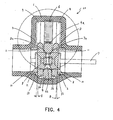
- FIG. 4 shows a section view of FIG. 2, along the line B-B.
- FIG. 5 shows the opening and closing states of a valve in FIG. 2.
- FIG. 6 shows the completely open state of the valve in FIG. 2.
- FIG. 2 is an exterior view of a valve device 20 according to an embodiment of the present invention, and the closed state of the valve is illustrated.
- FIG. 3 shows a section view of FIG. 2, along the line A-A.
- FIG. 4 shows a section view of FIG. 2, along the line B-B.
- FIG. 5 shows the opening and closing state of a valve in FIG. 2.
- FIG. 6 shows the completely open state of the valve in FIG. 2.
- FIG. 3 is used to illustrate the construction of the valve.
- a planetary mechanism 21 and valve plates 3 and 3 are accommodated in a frame body 1.
- the planetary mechanism 21 is composed with a sun gear 5 and a planetary component 4.
- a cavity is formed in the frame body 1, so as to provide an area for the opening and closing motion tracks of the planetary component 4 and for disposing components, such as the sun gear 5, that are used to drive the valve to perform the opening and closing motions in the cavity.
- Two opening portions, used as pipe end portions and connected to pipe components, are formed on the left and right sides of the valve device 20.
- an internal gear 6 constituting a part of the planetary gear mechanism is formed, and the internal gear 6 regulates an area for revolution motion track of the planetary component 4.
- Two opposite guide pieces 9 and 9 are formed in the frame body 1 at two positions.
- the guide pieces 9 have taper surfaces, and the guide pieces 9 constitute the guide faces when the valve plates 3 on the two sides of the planetary component 4 perform the revolution motion of opening and closing.
- a pair of shoulders 13 is disposed on the left and the right sides.
- Ring shaped valve seats 2 pass through the shoulders 13.
- closing faces 11 of the valve seats 2 tilted by an angle ⁇ are formed along the direction of the revolution motion of the valve plates 3.
- Curved protrusions 3a are disposed on the centers of the inner sides of the seal faces of two valve plates 3.
- outer periphery portions 3b of the valve plates 3 are curved surfaces.
- a planetary gear 4a is formed on the periphery of the planetary component 4, and the inner diameter surface of the hole portion 4b of the planetary component 4 is a curved surface.
- a sun gear 5 is connected with a driving shaft 7 to form an integrated component.
- the driving shaft 7 is connected to a handle or a turning driving device which is not shown in the figure, and is used as an external operating portion of the valve to transmit the turning motion of the handle or the turning driving device to the sun gear 5.
- the two independent valve plates 3 approximately and synchronously roll with the rotation motion of the planetary component 4 to perform the revolution motion.
- the contacting faces of the guide members 8 and the outer periphery portions of the valve plates 3 are taper surfaces.
- the guide pieces 9 carries out the guidance for the valve plates 3 and the planetary component 4 performing the revolution motion move towards the valve seats 2 together, during the opening and the closing of the valve.
- Two guide pieces 9 are formed neighboring the area for the revolution motion track of the planetary component 4 in the frame body 1.
- the guide faces of the guide pieces 9 are taper surfaces.
- the outer periphery portions 3b of the valve plates 3 are in rolling contact with the guide members 8 and the guide pieces 9, such that the valve plates 3 can smoothly move during the opening and the closing of the valve.
- the outer periphery portions 3b of the valve plates 3 are in sliding contact with the end surfaces 10 of the inner diameters of the valve seats 2. Concurrently, the outer periphery portions 3b of the valve plates 3 enter into the inner diameters of the valve seats 2. In order not to obstruct the opening and closing motions of the valve plates 3 because the outer periphery portions 3b are pressed toward the inner diameter parts of the valve seats 2, the outer periphery portions 3b of the valve plates 3 are provided as curved surfaces. More desirably, the outer periphery portions 3b of the valve plates 3 have the following surface layers, and a surface treatment for reducing friction is performed on the surface layers.
- the opening and closing motions of the valve plates 3 become smooth.
- the outer periphery portions 3b of the valve plates 3 are in sliding contact with the end surfaces 10 of the inner diameters of the valve seats 2.
- the outer periphery portions 3b of the valves plates 3 enter into the inner diameters of the valve seats 2.
- the end surfaces 10 of the inner diameters of the valve seats 2 are provided as curved surfaces relative to the flow path center. More desirably, the end surfaces 10 of the inner diameters of the valve seats 2 have the following surface layers, and a surface treatment for reducing friction is performed on the surface layer. In this manner, the opening and closing motions of the valve plates 3 become smooth.
- valve device of the present invention is illustrated according to FIG. 3.
- the sun gear 5, the planetary component 4, and the internal gear 6 form the planetary gear mechanism. After the handle or the external driving device connected to the driving shaft 7 is driven, causing the driving shaft 7 to turn, the sun gear 5 is turned, and the planetary component 4 engaged with the sun gear 5 is turned and starts to rotate.
- the planetary component 4 is engaged with the internal gear 6, so the planetary component 4 revolves in an arc manner along the internal gear 6.
- the protrusion portions 3a of the valve plates 3 are disposed in the inner diameter of the hole of the planetary component 4.
- the motion of the valve plates 3 is limited, so the valve plates 3 move with the revolution motion of the planetary component 4 towards the direction of the valve seats 2.
- valve plates 3 which are in rolling contact with the guide pieces 9 and the guide members 8, move with the revolution motion of the planetary component 4 towards the direction of the valve seats 2. However, the valve plates 3 rotate together with the rotation motion of the planetary component 4. The valve plates 3 are in rolling contact with the guide pieces 9. Further, the valve plates 3 are also in rolling contact with the guide members 8, wherein the guide members 8 is disposed on the driving shaft 7 and spin freely, to greatly reduce the friction, which obstruct the valve plates 3 from moving, between the valve plates 3 and the guide pieces 9 and the guide members 8.
- the other contact portion P2 is in sliding contact, but the outer peripheries 3b of the valve plates 3 and the end surfaces 10 of the inner diameters of the valve seats 2 are curved surfaces. Therefore, the sliding contact is relatively smooth, and a relatively small driving force is required for - the valve plates 3 to successively perform the opening and the closing motions.
- the outer peripheries 3b of the valve plates 3 are also provided as curved surfaces in a manner opposite to the end surfaces 10 of the inner diameters of the valve seats 2, wherein the valve seats 2 form the curved surface relative to the center of the flow path.
- the end surfaces 10 of the inner diameters of the valve seats 2 are provided to have the surface layers with relatively low friction, such that the outer peripheries 3b of the valve plates 3 are in sliding contact with the curved surfaces of the end surfaces 10 of the inner diameters of the valve seats 2.
- valve plates 3 move towards the direction of closing the valve seats 2.
- the downstream side valve plates 3 reach the position for blocking the entire inner diameter of the valve seats 2 disposed at the exit side, in the outer peripheries 3b of the valve plates 3, the moving direction portion of the valve plates 3 leaves the end surfaces 10 of the inner diameters of the valve seats 2, and the seal faces of the valve plates 3 and the seal faces of the valve seats 2 become in agreement.
- the valve plates 3 at the downstream side rotate along the seal face of the tilted valve seats 2, and the valve plates 3 slide.
- the planetary component 4 and the two valve plates 3 reach the seal faces of the valve seats 2.
- the combination of the two valve plates 3 and the planetary component 4 moves till the position held by the two valve seats 2 to complete the closing motion of the valve.
- the two valve plates 3 generate a closing force of the valve at the seal faces of the opposite valve seats 2 through the planetary component 4, so as to fully prevent the fluid from flowing.
- the planetary component 4 is not limited to be ring shape, even if the both positions of the central portion of the planetary component 4 are the indented portions, the planetary component 4 can still function normally.
- the present invention provides the valve device as follows.
- the valve plate having degrees of freedom can effectively demonstrate the degrees of freedom by the rolling motion.
- the seal faces of the valve plates can easily follow the seal faces of the two opposite valve seats, and are tightly seal with the seal faces of the two valve seats. Therefore, the closing function of the valve is greatly improved, the adjustment process is reduced, and the manufacturing is more cost-effective because of the relatively large degrees of freedom.
- the thrust required by the valve plates is transmitted from the driving gear and through the planetary component. As a result, the driving force applied on the driving shaft is one half of the thrust required for the opening and closing of the valve under leverage effect.
- the rolling motion of the valve plates can reduce the friction loss of driving transmitting force. Hence, the operating force for the opening and the close of the valve is reduced. Further, the opening and the closing speeds are relatively high to achieve quick opening and closing, and the space occupied is reduced.
Landscapes
- Engineering & Computer Science (AREA)
- General Engineering & Computer Science (AREA)
- Mechanical Engineering (AREA)
- Sliding Valves (AREA)
- Mechanically-Actuated Valves (AREA)
Abstract
Description
- The present invention relates to a valve device using a planetary component for opening and closing a valve plate.
- As an embedded valve device embedding valve plates between opposite valve seats, a sluice valve is known to the prior art (referring to FIG. 1 of Patent Reference 1). However, in order to open and close a valve, it is necessary to turn a
handle 30. Hence, a relatively long time is required for the opening and the closing of the valve. In addition, the height of the valve is relatively large, and a relatively great thrust is required to open and to close the valve. Further, in order to ensure that thevalve plate 31 is closed, it is necessary to perform an adjustment (processing), so as to assure the tight sealing of the seal faces of thevalve plates 31 and thevalve seats 32. - In view of the problems that the time for the opening and closing of the valve becomes longer and the height of the valve device becomes larger, a following method is considered, in which a planetary gear is used in constituting the valve plates to solve the problems (
Patent Reference 2 and Patent Reference 3). - [Patent Reference 1]
Japanese Patent Utility Model Publication No. JP 56-76773U - [Patent Reference 2]
Japanese Patent Publication No. JP 61-59435B - [Patent Reference 3]
Japanese Patent Publication No.JP 63-46309B - However, the valve plates are in sliding contact with the guide portions of the valve plates when the planetary gear is used in constituting the valve plate. Further, due to the tolerances or mutual friction of the teeth of the planetary gear, the sun gear, and the internal gear, the degree of freedom of the valve plate becomes limited. Therefore, the valve function of closing the valve plates and the valve seats, i.e. the closing capability, is inadequate.
- In addition, the following aspects still require improvement. The seal faces of the valve seats are in sliding contact with the moving valve plates, such that the seal faces are damaged, inducing an adverse effect on the closing function of the valve.
- In another aspect, when the planetary gear is used in constituting the valve plates, the following problem is still unsolved. That is, it is necessary to reduce the current operating force on the sluice valve; or in order to assure the closing function of the valve, it is necessary to perform the adjustment (processing).
- In order to solve the above problems, in the valve device of the present invention, valve plates are inserted between a pair of valve seats that are disposed in a flow path and are opposite to each other, or the valve plates are removed so as to open or to close the flow path. The valve device is characterized by including an arc-shaped internal gear formed in a frame body of the valve device; a sun gear disposed on a center of the arc-shaped internal gear; a driving shaft connected on the sun gear; a planetary component engaged with the internal gear and the sun gear; and a pair of valve plates disposed on both sides of the planetary component. Further, a central portion of the valve plate is embedded in the planetary component in a manner that the central portion of the valve plate is capable of rolling freely. By turning of the driving shaft, the pair of the valve plates is inserted between the valve seats or is detached from the valve seats for constituting an opening and closing the flow path. In such an opening and closing assembly, protrusion portions are disposed on the centers of inner sides of seal faces of the pair of the valve plates. In another aspect, an inner diameter side of the planetary component is in rolling contact with the protrusion portions of the valve plates, such that a turning driving force of the planetary component used as a tightening force of the valve plates is transmitted to the pair of valve seats. Ultimately, the pair of valve plates moves towards the pair of valve seats, and seal faces of the valve seats tilt towards the moving direction of the valve plates.
- Also, the present invention is characterized by configuring the protrusion portions of the valve plates opposite to the inner diameter side of the planetary component, and by providing the inner periphery of the planetary component be taper surfaces or curved surfaces, such that the valve plate is embedded in a hole portion of the planetary component in a manner that the valve plate swings freely.
- Further, the present invention is characterized by disposing guide members supporting outer peripheries of the valve plates on the driving shaft in a manner that the guide members supporting outer peripheries of the valve plates spin freely, so as to prevent sides of the sun gear of the pair of valve plates from separating.
- In addition, the present invention is characterized by providing the contact portions of the guide members and the inner face of the frame body be taper surfaces or curved surfaces, and by providing the outer peripheries of the valve plates be curved surfaces or taper surfaces, so as to allow the contact portions and the outer peripheries of the valve plates be in point contact.
- Also, the present invention is characterized by forming guide portions on the inner peripheries of the valve seats. When the valve plates are moved towards a direction to block the flow path, the guide portions guide the outer peripheries of the valve plates. Further, the section of the guide portions has an arc shape.
- In addition, the present invention is characterized by using components with low friction to constitute the outer peripheries of the valve plates and end surfaces of the inner diameters of the valve seats, and to promote the outer peripheries of the valve plates in slidable contact with the end surfaces of the inner diameters of the valve seats. Hence, the contact portions of the outer peripheries of the valve plates and the end surfaces of the inner diameters of the valve seats are protected.
- In order to achieve the aforementioned and other objects, features and advantages of the present invention comprehensible, preferred embodiments accompanied with figures are described in detail below.
- It is to be understood that both the foregoing general description and the following detailed description are exemplary, and are intended to provide further explanation of the invention as claimed.
- The accompanying drawings are included to provide a further understanding of the invention, and are incorporated in and constitute a part of this specification. The drawings illustrate embodiments of the invention and, together with the description, serve to explain the principles of the invention.
- FIG. 1 is a structural diagram of a current sluice valve.
- FIG. 2 is an exterior view of a valve device according to an embodiment of the present invention, and the closed state of the valve is illustrated.
- FIG. 3 shows a section view of FIG. 2, along the line A-A.
- FIG. 4 shows a section view of FIG. 2, along the line B-B.
- FIG. 5 shows the opening and closing states of a valve in FIG. 2.
- FIG. 6 shows the completely open state of the valve in FIG. 2.
- In order to describe the present invention in detail, the illustration is provided with reference to the accompanying drawings. FIG. 2 is an exterior view of a
valve device 20 according to an embodiment of the present invention, and the closed state of the valve is illustrated. FIG. 3 shows a section view of FIG. 2, along the line A-A. FIG. 4 shows a section view of FIG. 2, along the line B-B. FIG. 5 shows the opening and closing state of a valve in FIG. 2. FIG. 6 shows the completely open state of the valve in FIG. 2. FIG. 3 is used to illustrate the construction of the valve. - A
planetary mechanism 21 andvalve plates planetary mechanism 21 is composed with asun gear 5 and a planetary component 4. A cavity is formed in the frame body 1, so as to provide an area for the opening and closing motion tracks of the planetary component 4 and for disposing components, such as thesun gear 5, that are used to drive the valve to perform the opening and closing motions in the cavity. Two opening portions, used as pipe end portions and connected to pipe components, are formed on the left and right sides of thevalve device 20. In the frame body 1, aninternal gear 6 constituting a part of the planetary gear mechanism is formed, and theinternal gear 6 regulates an area for revolution motion track of the planetary component 4. Twoopposite guide pieces guide pieces 9 have taper surfaces, and theguide pieces 9 constitute the guide faces when thevalve plates 3 on the two sides of the planetary component 4 perform the revolution motion of opening and closing. At the position connecting to the pipe component connected to the frame body 1 of thevalve device 20, a pair ofshoulders 13 is disposed on the left and the right sides. Ringshaped valve seats 2 pass through theshoulders 13. As shown in FIG. 4, closing faces 11 of thevalve seats 2 tilted by an angle θ are formed along the direction of the revolution motion of thevalve plates 3.Curved protrusions 3a are disposed on the centers of the inner sides of the seal faces of twovalve plates 3. Also, outer periphery portions 3b of thevalve plates 3 are curved surfaces. Aplanetary gear 4a is formed on the periphery of the planetary component 4, and the inner diameter surface of the hole portion 4b of the planetary component 4 is a curved surface. Asun gear 5 is connected with a drivingshaft 7 to form an integrated component. The drivingshaft 7 is connected to a handle or a turning driving device which is not shown in the figure, and is used as an external operating portion of the valve to transmit the turning motion of the handle or the turning driving device to thesun gear 5. Twoguide members 8, disposed on two positions of a shaft same as the drivingshaft 7 in a manner that the twoguide members 8 spin freely and guide twoindependent valve plates 3 during the opening and the closing of the valve. The twoindependent valve plates 3 approximately and synchronously roll with the rotation motion of the planetary component 4 to perform the revolution motion. The contacting faces of theguide members 8 and the outer periphery portions of thevalve plates 3 are taper surfaces. Theguide pieces 9 carries out the guidance for thevalve plates 3 and the planetary component 4 performing the revolution motion move towards thevalve seats 2 together, during the opening and the closing of the valve. Twoguide pieces 9 are formed neighboring the area for the revolution motion track of the planetary component 4 in the frame body 1. The guide faces of theguide pieces 9 are taper surfaces. During the opening and closing of the valve, the outer periphery portions 3b of thevalve plates 3 are in rolling contact with theguide members 8 and theguide pieces 9, such that thevalve plates 3 can smoothly move during the opening and the closing of the valve. Also, during the rolling motion of thevalve plates 3, the outer periphery portions 3b of thevalve plates 3 are in sliding contact with the end surfaces 10 of the inner diameters of the valve seats 2. Concurrently, the outer periphery portions 3b of thevalve plates 3 enter into the inner diameters of the valve seats 2. In order not to obstruct the opening and closing motions of thevalve plates 3 because the outer periphery portions 3b are pressed toward the inner diameter parts of thevalve seats 2, the outer periphery portions 3b of thevalve plates 3 are provided as curved surfaces. More desirably, the outer periphery portions 3b of thevalve plates 3 have the following surface layers, and a surface treatment for reducing friction is performed on the surface layers. In this manner, the opening and closing motions of thevalve plates 3 become smooth. When thevalve plates 3 perform the rolling motion, the outer periphery portions 3b of thevalve plates 3 are in sliding contact with the end surfaces 10 of the inner diameters of the valve seats 2. Concurrently, the outer periphery portions 3b of thevalves plates 3 enter into the inner diameters of the valve seats 2. Instantly, in order not to obstruct the opening and closing motions of thevalve plates 3 due to the compression on the inner diameter parts of thevalve seats 2 by the outer periphery portions 3b of thevalve plates 3, the end surfaces 10 of the inner diameters of thevalve seats 2 are provided as curved surfaces relative to the flow path center. More desirably, the end surfaces 10 of the inner diameters of thevalve seats 2 have the following surface layers, and a surface treatment for reducing friction is performed on the surface layer. In this manner, the opening and closing motions of thevalve plates 3 become smooth. - In the followings, the actuation of the valve device of the present invention is illustrated according to FIG. 3.
- The
sun gear 5, the planetary component 4, and theinternal gear 6 form the planetary gear mechanism. After the handle or the external driving device connected to the drivingshaft 7 is driven, causing the drivingshaft 7 to turn, thesun gear 5 is turned, and the planetary component 4 engaged with thesun gear 5 is turned and starts to rotate. - Also, the planetary component 4 is engaged with the
internal gear 6, so the planetary component 4 revolves in an arc manner along theinternal gear 6. Theprotrusion portions 3a of thevalve plates 3 are disposed in the inner diameter of the hole of the planetary component 4. On theguide pieces 9 or theguide members 8, and the inner diameter face of the hole portion 4b of the planetary component 4, the motion of thevalve plates 3 is limited, so thevalve plates 3 move with the revolution motion of the planetary component 4 towards the direction of the valve seats 2. - The
valve plates 3, which are in rolling contact with theguide pieces 9 and theguide members 8, move with the revolution motion of the planetary component 4 towards the direction of the valve seats 2. However, thevalve plates 3 rotate together with the rotation motion of the planetary component 4. Thevalve plates 3 are in rolling contact with theguide pieces 9. Further, thevalve plates 3 are also in rolling contact with theguide members 8, wherein theguide members 8 is disposed on the drivingshaft 7 and spin freely, to greatly reduce the friction, which obstruct thevalve plates 3 from moving, between thevalve plates 3 and theguide pieces 9 and theguide members 8. - As the
valve plates 3 approach thevalve seats 2, the dynamic pressure generated due to the flowing of the fluid pushes thevalve plates 3 to the exit side of the valve seats 2. Instantly, in the above-mentioned revolution motion, the outer peripheries 3b of thevalve plates 3 enter into the inner diameters of thevalve seats 2, and the outer peripheries 3b of thevalve plates 3 contact with the end surfaces 10 of the inner diameters of the valve seats 2. However, as shown in FIG. 5, at the contact portions P1 and P2 corresponding to the end surfaces 10 of the inner diameters of thevalve seats 2, the contact portion P1 of the outer side is in rolling contact because of the tendency of the rotation motion of thevalve plates 3. The other contact portion P2 is in sliding contact, but the outer peripheries 3b of thevalve plates 3 and the end surfaces 10 of the inner diameters of thevalve seats 2 are curved surfaces. Therefore, the sliding contact is relatively smooth, and a relatively small driving force is required for - thevalve plates 3 to successively perform the opening and the closing motions. - In addition, the outer peripheries 3b of the
valve plates 3 are also provided as curved surfaces in a manner opposite to the end surfaces 10 of the inner diameters of thevalve seats 2, wherein thevalve seats 2 form the curved surface relative to the center of the flow path. Also, in order to protect the contact portions, the end surfaces 10 of the inner diameters of thevalve seats 2 are provided to have the surface layers with relatively low friction, such that the outer peripheries 3b of thevalve plates 3 are in sliding contact with the curved surfaces of the end surfaces 10 of the inner diameters of the valve seats 2. - With the revolution motion of the planetary component 4, the
valve plates 3 move towards the direction of closing the valve seats 2. After the downstreamside valve plates 3 reach the position for blocking the entire inner diameter of thevalve seats 2 disposed at the exit side, in the outer peripheries 3b of thevalve plates 3, the moving direction portion of thevalve plates 3 leaves the end surfaces 10 of the inner diameters of thevalve seats 2, and the seal faces of thevalve plates 3 and the seal faces of thevalve seats 2 become in agreement. Instantly, thevalve plates 3 at the downstream side rotate along the seal face of the tiltedvalve seats 2, and thevalve plates 3 slide. - Next, the planetary component 4 and the two
valve plates 3 reach the seal faces of the valve seats 2. The combination of the twovalve plates 3 and the planetary component 4 moves till the position held by the twovalve seats 2 to complete the closing motion of the valve. Under such a condition, the twovalve plates 3 generate a closing force of the valve at the seal faces of theopposite valve seats 2 through the planetary component 4, so as to fully prevent the fluid from flowing. - In the above disclosure, the closing motion of the valve is illustrated. Since the motion that the valve changes from a closing state to an opening state is a reverse of the closing motion of the valve, detail description thereof will not be reiterated herein.
- In the above description, one embodiment of the present invention is illustrated. However it is to be understood that the embodiment is presented by way of example and not by way of limitation. The above description is intended to cover all modification, alternatives and equivalents of the invention. For example, the planetary component 4 is not limited to be ring shape, even if the both positions of the central portion of the planetary component 4 are the indented portions, the planetary component 4 can still function normally.
- [Industrial Applicability]
- As described above, the present invention provides the valve device as follows. During the opening and closing motions of the valve, the valve plate having degrees of freedom can effectively demonstrate the degrees of freedom by the rolling motion. In this manner, the seal faces of the valve plates can easily follow the seal faces of the two opposite valve seats, and are tightly seal with the seal faces of the two valve seats. Therefore, the closing function of the valve is greatly improved, the adjustment process is reduced, and the manufacturing is more cost-effective because of the relatively large degrees of freedom. In another aspect, the thrust required by the valve plates is transmitted from the driving gear and through the planetary component. As a result, the driving force applied on the driving shaft is one half of the thrust required for the opening and closing of the valve under leverage effect. Further, the rolling motion of the valve plates can reduce the friction loss of driving transmitting force. Hence, the operating force for the opening and the close of the valve is reduced. Further, the opening and the closing speeds are relatively high to achieve quick opening and closing, and the space occupied is reduced.
- It will be apparent to those skilled in the art that various modifications and variations can be made to the structure of the present invention without departing from the scope or spirit of the invention. In view of the foregoing, it is intended that the present invention cover modifications and variations of this invention provided they fall within the scope of the following claims and their equivalents.
Claims (6)
- A valve device, wherein valve plates are inserted between or detached from a pair of valve seats opposite to each other disposed in a flow path to open or to close the flow path,
the valve device comprising:an arc shaped internal gear, formed in a frame body of the valve device;a sun gear, disposed on a center of the arc shaped internal gear;a driving shaft, connecting on the sun gear, wherein the driving shaft is capable of turning freely;a planetary component, engaged with the internal gear and the sun gear; anda pair of valve plates, disposed on both sides of the planetary component, wherein a central portion of the valve plate is embedded in the planetary component in a manner that the central portion of the valve plate spins freely,wherein by turning of the driving shaft forward and backward, the pair of the valve plates is inserted between the valve seats or detached from the valve seats to constitute an opening and a closing assembly of the flow path;
a protrusion portion of the valve plates is disposed on a center of an inner side of a seal face of the pair of the valve plates in the assembly, and
an inner diameter side of the planetary component is in rolling contact with the protrusion portion of the valve plates, such that a turning driving force of the planetary component, used as a tightening force of the valve plates, is transmitted to the pair of valve seats, and the pair of valve plates moves towards the pair of valve seats, and the valve seats tilt towards a moving direction of the valve plates. - The valve device as claimed in claim 1, wherein:the protrusion portion of the valve plates opposite to the inner diameter side of the planetary component, and an inner periphery of the planetary component are provided as taper surfaces or curved surfaces, such that the valve plates are embedded into a hole portion of the planetary component in a manner that the valve plates swing freely.
- The valve device as claimed in claim 1~2, wherein:guide members supporting outer peripheries of the valve plates are disposed on the driving shaft in a manner that the guide members supporting outer peripheries of the valve plates spin freely to prevent sides of the sun gear of the pair of valve plates from separating.
- The valve device as claimed in claim 1~3, wherein:contact portions of the guide members toward the outer peripheries of the valve plates and contact portions of the inner face of the frame body are provided as taper surfaces or curved surfaces, andouter peripheries of the valve plates are provided as curved surfaces or taper surfaces for the contact portions be in point contact with the outer peripheries of the valve plates.
- The valve device as claimed in claim 1~4, wherein:guide portions are formed on inner peripheries of the valve seats, when the valve plates are moved towards a direction to block a flow path, the guide portions guide the outer peripheries of the valve plates, and sections of the guide portions are arc shape.
- The valve device as claimed in claim 1~5, wherein:components with low friction are used to form the guide portions having the arc shape sections and disposed on the inner peripheries of the valve seats and the outer peripheries of the valve plates.
Applications Claiming Priority (2)
| Application Number | Priority Date | Filing Date | Title |
|---|---|---|---|
| JP2005160419A JP3793974B1 (en) | 2005-04-28 | 2005-04-28 | Valve device |
| PCT/JP2006/307514 WO2006117978A1 (en) | 2005-04-28 | 2006-04-03 | Valve device |
Publications (3)
| Publication Number | Publication Date |
|---|---|
| EP1878956A1 true EP1878956A1 (en) | 2008-01-16 |
| EP1878956A4 EP1878956A4 (en) | 2010-01-06 |
| EP1878956B1 EP1878956B1 (en) | 2010-09-01 |
Family
ID=36739882
Family Applications (1)
| Application Number | Title | Priority Date | Filing Date |
|---|---|---|---|
| EP06731461A Expired - Lifetime EP1878956B1 (en) | 2005-04-28 | 2006-04-03 | Valve device |
Country Status (4)
| Country | Link |
|---|---|
| US (1) | US7543797B2 (en) |
| EP (1) | EP1878956B1 (en) |
| JP (1) | JP3793974B1 (en) |
| WO (1) | WO2006117978A1 (en) |
Families Citing this family (2)
| Publication number | Priority date | Publication date | Assignee | Title |
|---|---|---|---|---|
| CN107514910A (en) * | 2017-08-16 | 2017-12-26 | 阿尔赛(苏州)无机材料有限公司 | Sintering furnace exhaust baffle mechanism with precise and adjustable opening |
| CN109027284B (en) * | 2018-10-22 | 2020-02-14 | 哈尔滨工程大学 | Flow linear regulating valve controlled by PLC (programmable logic controller) by utilizing inlet incoming flow parameters |
Family Cites Families (19)
| Publication number | Priority date | Publication date | Assignee | Title |
|---|---|---|---|---|
| US284122A (en) * | 1883-08-28 | Straightaway valve | ||
| US88934A (en) * | 1869-04-13 | Improvement in stop-valves for steam and other enginery | ||
| US450588A (en) * | 1891-04-14 | Heimee | ||
| US711262A (en) * | 1902-05-03 | 1902-10-14 | Leo A Riegler | Expanding gate-valve. |
| US1437426A (en) * | 1919-07-23 | 1922-12-05 | Jr Willard A Kitts | Blow-off valve |
| US1421687A (en) * | 1920-12-15 | 1922-07-04 | George P Haynes | Valve |
| US1574959A (en) * | 1922-06-21 | 1926-03-02 | Springfield Lumber Company | Valve-mechanism control |
| US2611575A (en) * | 1938-02-28 | 1952-09-23 | Jenkins Bros | Quick-acting gate valve |
| US2272110A (en) * | 1940-07-17 | 1942-02-03 | James W Childress | Hydraulic valve |
| US2895709A (en) * | 1955-03-22 | 1959-07-21 | Rattigan A Frieda | Gate valve |
| US3325141A (en) * | 1964-09-24 | 1967-06-13 | Skendrovic Lawrence | Full flow valve |
| JPS54153325A (en) | 1978-05-24 | 1979-12-03 | Hitachi Ltd | Nonnshock fluid path changeeover controlling method |
| JPS54153328A (en) * | 1978-05-25 | 1979-12-03 | Nakamura Kinzoku Kogyosho | Sluice valve device |
| JPS6027871B2 (en) | 1979-11-26 | 1985-07-01 | 株式会社ターダ | Gas main valve with electric outlet |
| JPS5923170A (en) * | 1982-07-30 | 1984-02-06 | Shimadzu Corp | Valve device |
| JPS6159435A (en) | 1984-08-31 | 1986-03-26 | Canon Inc | camera photometry device |
| JPS6346309A (en) | 1986-08-12 | 1988-02-27 | Mitsubishi Electric Corp | Liquid fuel fired device |
| US5284320A (en) * | 1992-08-12 | 1994-02-08 | Halliburton Company | Surface valve with pressure energized seal and gear actuation |
| JP2005160419A (en) | 2003-12-04 | 2005-06-23 | Ezaki Glico Co Ltd | Foamed chocolate with characteristic shape and method for producing the same |
-
2005
- 2005-04-28 JP JP2005160419A patent/JP3793974B1/en not_active Expired - Fee Related
-
2006
- 2006-04-03 WO PCT/JP2006/307514 patent/WO2006117978A1/en not_active Ceased
- 2006-04-03 US US11/910,209 patent/US7543797B2/en not_active Expired - Fee Related
- 2006-04-03 EP EP06731461A patent/EP1878956B1/en not_active Expired - Lifetime
Also Published As
| Publication number | Publication date |
|---|---|
| WO2006117978A1 (en) | 2006-11-09 |
| US20090072178A1 (en) | 2009-03-19 |
| JP3793974B1 (en) | 2006-07-05 |
| US7543797B2 (en) | 2009-06-09 |
| JP2006308069A (en) | 2006-11-09 |
| EP1878956A4 (en) | 2010-01-06 |
| EP1878956B1 (en) | 2010-09-01 |
Similar Documents
| Publication | Publication Date | Title |
|---|---|---|
| JP4683159B1 (en) | Rotary valve | |
| JP4192193B2 (en) | Ball valve | |
| JP3726815B2 (en) | Flow control valve | |
| EP3244104B1 (en) | Butterfly valve | |
| KR100483543B1 (en) | Valve driver and series of the same | |
| US20030150495A1 (en) | Valve driving device | |
| JP2010185464A (en) | Check valve | |
| KR101804249B1 (en) | triple offset butterfly valve | |
| EP1878956B1 (en) | Valve device | |
| US20070144854A1 (en) | Two-way clutch | |
| JP3550513B2 (en) | Butterfly valve body with double eccentric structure | |
| US4482128A (en) | High pressure cam seal valve | |
| JP2000314456A (en) | Planetary gear reducer | |
| TW202018205A (en) | Spline structure, decelerating or accelerating device, and constant-speed joint | |
| EP4677250B1 (en) | Low operating torque non-contact valve | |
| JP5736064B1 (en) | A clutch transmission that converts the input of a non-continuously rotating power input shaft into two coaxial outputs that are not driven simultaneously | |
| WO2016136643A1 (en) | Flow passage opening/closing valve | |
| KR101139789B1 (en) | Butterfly valve having moving disc | |
| KR101404656B1 (en) | Ball valve for waterworks | |
| CN223270636U (en) | Side-drive butterfly valve mechanism for flow control | |
| JPH11344136A (en) | Rotor valve | |
| JP2007040213A (en) | Exhaust brake valve device | |
| KR20250160568A (en) | Multi port ball valve for preventing leakage | |
| KR100512919B1 (en) | A valve | |
| KR100509237B1 (en) | Trunk seat ball style metal seat butter fly valve |
Legal Events
| Date | Code | Title | Description |
|---|---|---|---|
| PUAI | Public reference made under article 153(3) epc to a published international application that has entered the european phase |
Free format text: ORIGINAL CODE: 0009012 |
|
| 17P | Request for examination filed |
Effective date: 20071119 |
|
| AK | Designated contracting states |
Kind code of ref document: A1 Designated state(s): AT BE BG CH LI |
|
| RBV | Designated contracting states (corrected) |
Designated state(s): FR GB IT NL |
|
| DAX | Request for extension of the european patent (deleted) | ||
| RBV | Designated contracting states (corrected) |
Designated state(s): FR GB IT NL |
|
| A4 | Supplementary search report drawn up and despatched |
Effective date: 20091203 |
|
| GRAP | Despatch of communication of intention to grant a patent |
Free format text: ORIGINAL CODE: EPIDOSNIGR1 |
|
| GRAS | Grant fee paid |
Free format text: ORIGINAL CODE: EPIDOSNIGR3 |
|
| GRAA | (expected) grant |
Free format text: ORIGINAL CODE: 0009210 |
|
| AK | Designated contracting states |
Kind code of ref document: B1 Designated state(s): FR GB IT NL |
|
| REG | Reference to a national code |
Ref country code: GB Ref legal event code: FG4D |
|
| REG | Reference to a national code |
Ref country code: NL Ref legal event code: T3 |
|
| PLBE | No opposition filed within time limit |
Free format text: ORIGINAL CODE: 0009261 |
|
| STAA | Information on the status of an ep patent application or granted ep patent |
Free format text: STATUS: NO OPPOSITION FILED WITHIN TIME LIMIT |
|
| 26N | No opposition filed |
Effective date: 20110606 |
|
| PGFP | Annual fee paid to national office [announced via postgrant information from national office to epo] |
Ref country code: NL Payment date: 20120404 Year of fee payment: 7 |
|
| PGFP | Annual fee paid to national office [announced via postgrant information from national office to epo] |
Ref country code: IT Payment date: 20120426 Year of fee payment: 7 |
|
| PGFP | Annual fee paid to national office [announced via postgrant information from national office to epo] |
Ref country code: GB Payment date: 20130423 Year of fee payment: 8 |
|
| PGFP | Annual fee paid to national office [announced via postgrant information from national office to epo] |
Ref country code: FR Payment date: 20130417 Year of fee payment: 8 |
|
| REG | Reference to a national code |
Ref country code: NL Ref legal event code: V1 Effective date: 20131101 |
|
| PG25 | Lapsed in a contracting state [announced via postgrant information from national office to epo] |
Ref country code: NL Free format text: LAPSE BECAUSE OF NON-PAYMENT OF DUE FEES Effective date: 20131101 Ref country code: IT Free format text: LAPSE BECAUSE OF NON-PAYMENT OF DUE FEES Effective date: 20130403 |
|
| GBPC | Gb: european patent ceased through non-payment of renewal fee |
Effective date: 20140403 |
|
| REG | Reference to a national code |
Ref country code: FR Ref legal event code: ST Effective date: 20141231 |
|
| PG25 | Lapsed in a contracting state [announced via postgrant information from national office to epo] |
Ref country code: GB Free format text: LAPSE BECAUSE OF NON-PAYMENT OF DUE FEES Effective date: 20140403 |
|
| PG25 | Lapsed in a contracting state [announced via postgrant information from national office to epo] |
Ref country code: FR Free format text: LAPSE BECAUSE OF NON-PAYMENT OF DUE FEES Effective date: 20140430 |