EP1879008A2 - Flexibles System und Verfahren zum Erkennen von Undichtigkeiten für einen Schlauch mit doppelter Karkasse - Google Patents
Flexibles System und Verfahren zum Erkennen von Undichtigkeiten für einen Schlauch mit doppelter Karkasse Download PDFInfo
- Publication number
- EP1879008A2 EP1879008A2 EP07013805A EP07013805A EP1879008A2 EP 1879008 A2 EP1879008 A2 EP 1879008A2 EP 07013805 A EP07013805 A EP 07013805A EP 07013805 A EP07013805 A EP 07013805A EP 1879008 A2 EP1879008 A2 EP 1879008A2
- Authority
- EP
- European Patent Office
- Prior art keywords
- sensor
- fluid
- hose
- housing
- leak detection
- Prior art date
- Legal status (The legal status is an assumption and is not a legal conclusion. Google has not performed a legal analysis and makes no representation as to the accuracy of the status listed.)
- Granted
Links
- 238000001514 detection method Methods 0.000 title claims abstract description 50
- 238000000034 method Methods 0.000 title claims description 5
- 239000012530 fluid Substances 0.000 claims abstract description 57
- 238000004891 communication Methods 0.000 claims abstract description 17
- 230000008878 coupling Effects 0.000 claims abstract description 14
- 238000010168 coupling process Methods 0.000 claims abstract description 14
- 238000005859 coupling reaction Methods 0.000 claims abstract description 14
- 230000003287 optical effect Effects 0.000 claims description 22
- 230000005540 biological transmission Effects 0.000 claims description 10
- 239000013307 optical fiber Substances 0.000 claims description 10
- 230000008859 change Effects 0.000 claims description 9
- 238000013500 data storage Methods 0.000 claims description 4
- 238000011156 evaluation Methods 0.000 abstract 1
- 238000012544 monitoring process Methods 0.000 description 10
- 238000010276 construction Methods 0.000 description 8
- 239000000835 fiber Substances 0.000 description 8
- XLYOFNOQVPJJNP-UHFFFAOYSA-N water Substances O XLYOFNOQVPJJNP-UHFFFAOYSA-N 0.000 description 7
- 238000007667 floating Methods 0.000 description 5
- 210000003128 head Anatomy 0.000 description 4
- 230000000712 assembly Effects 0.000 description 3
- 238000000429 assembly Methods 0.000 description 3
- 230000014759 maintenance of location Effects 0.000 description 3
- 238000004519 manufacturing process Methods 0.000 description 3
- 210000002445 nipple Anatomy 0.000 description 3
- 238000013022 venting Methods 0.000 description 3
- 239000003795 chemical substances by application Substances 0.000 description 2
- 230000006835 compression Effects 0.000 description 2
- 238000007906 compression Methods 0.000 description 2
- 238000013480 data collection Methods 0.000 description 2
- 230000000694 effects Effects 0.000 description 2
- 238000011065 in-situ storage Methods 0.000 description 2
- 238000007689 inspection Methods 0.000 description 2
- 239000000463 material Substances 0.000 description 2
- 238000007789 sealing Methods 0.000 description 2
- 230000008054 signal transmission Effects 0.000 description 2
- 230000011664 signaling Effects 0.000 description 2
- 238000003860 storage Methods 0.000 description 2
- 239000012815 thermoplastic material Substances 0.000 description 2
- 230000000007 visual effect Effects 0.000 description 2
- 229910000831 Steel Inorganic materials 0.000 description 1
- 230000009471 action Effects 0.000 description 1
- 230000004913 activation Effects 0.000 description 1
- 238000004873 anchoring Methods 0.000 description 1
- 210000002159 anterior chamber Anatomy 0.000 description 1
- 238000013473 artificial intelligence Methods 0.000 description 1
- 239000011324 bead Substances 0.000 description 1
- 230000003139 buffering effect Effects 0.000 description 1
- 239000011248 coating agent Substances 0.000 description 1
- 238000000576 coating method Methods 0.000 description 1
- 230000007547 defect Effects 0.000 description 1
- 230000007812 deficiency Effects 0.000 description 1
- 230000002950 deficient Effects 0.000 description 1
- 238000013461 design Methods 0.000 description 1
- 238000010586 diagram Methods 0.000 description 1
- 238000009826 distribution Methods 0.000 description 1
- 230000007613 environmental effect Effects 0.000 description 1
- 238000004880 explosion Methods 0.000 description 1
- 238000003780 insertion Methods 0.000 description 1
- 230000037431 insertion Effects 0.000 description 1
- 230000007257 malfunction Effects 0.000 description 1
- 238000012986 modification Methods 0.000 description 1
- 230000004048 modification Effects 0.000 description 1
- 230000008439 repair process Effects 0.000 description 1
- 239000013535 sea water Substances 0.000 description 1
- 125000006850 spacer group Chemical group 0.000 description 1
- 239000010959 steel Substances 0.000 description 1
- 238000006467 substitution reaction Methods 0.000 description 1
- 230000009897 systematic effect Effects 0.000 description 1
- 229920001169 thermoplastic Polymers 0.000 description 1
- 239000004416 thermosoftening plastic Substances 0.000 description 1
- 238000012546 transfer Methods 0.000 description 1
- 210000000707 wrist Anatomy 0.000 description 1
Images


Classifications
-
- G—PHYSICS
- G01—MEASURING; TESTING
- G01M—TESTING STATIC OR DYNAMIC BALANCE OF MACHINES OR STRUCTURES; TESTING OF STRUCTURES OR APPARATUS, NOT OTHERWISE PROVIDED FOR
- G01M3/00—Investigating fluid-tightness of structures
- G01M3/38—Investigating fluid-tightness of structures by using light
-
- G—PHYSICS
- G01—MEASURING; TESTING
- G01M—TESTING STATIC OR DYNAMIC BALANCE OF MACHINES OR STRUCTURES; TESTING OF STRUCTURES OR APPARATUS, NOT OTHERWISE PROVIDED FOR
- G01M3/00—Investigating fluid-tightness of structures
- G01M3/02—Investigating fluid-tightness of structures by using fluid or vacuum
- G01M3/04—Investigating fluid-tightness of structures by using fluid or vacuum by detecting the presence of fluid at the leakage point
- G01M3/042—Investigating fluid-tightness of structures by using fluid or vacuum by detecting the presence of fluid at the leakage point by using materials which expand, contract, disintegrate, or decompose in contact with a fluid
- G01M3/045—Investigating fluid-tightness of structures by using fluid or vacuum by detecting the presence of fluid at the leakage point by using materials which expand, contract, disintegrate, or decompose in contact with a fluid with electrical detection means
- G01M3/047—Investigating fluid-tightness of structures by using fluid or vacuum by detecting the presence of fluid at the leakage point by using materials which expand, contract, disintegrate, or decompose in contact with a fluid with electrical detection means with photo-electrical detection means, e.g. using optical fibres
-
- G—PHYSICS
- G01—MEASURING; TESTING
- G01M—TESTING STATIC OR DYNAMIC BALANCE OF MACHINES OR STRUCTURES; TESTING OF STRUCTURES OR APPARATUS, NOT OTHERWISE PROVIDED FOR
- G01M3/00—Investigating fluid-tightness of structures
- G01M3/02—Investigating fluid-tightness of structures by using fluid or vacuum
- G01M3/26—Investigating fluid-tightness of structures by using fluid or vacuum by measuring rate of loss or gain of fluid, e.g. by pressure-responsive devices, by flow detectors
- G01M3/28—Investigating fluid-tightness of structures by using fluid or vacuum by measuring rate of loss or gain of fluid, e.g. by pressure-responsive devices, by flow detectors for pipes, cables or tubes; for pipe joints or seals; for valves ; for welds
- G01M3/2807—Investigating fluid-tightness of structures by using fluid or vacuum by measuring rate of loss or gain of fluid, e.g. by pressure-responsive devices, by flow detectors for pipes, cables or tubes; for pipe joints or seals; for valves ; for welds for pipes
- G01M3/283—Investigating fluid-tightness of structures by using fluid or vacuum by measuring rate of loss or gain of fluid, e.g. by pressure-responsive devices, by flow detectors for pipes, cables or tubes; for pipe joints or seals; for valves ; for welds for pipes for double-walled pipes
Definitions
- the invention relates generally to offshore oil load and discharge terminals and, more specifically, to hose leak detection systems deployed within the context of such oil load and discharge terminals.
- a "single carcass hose” is a hose construction comprising only one carcass layer. Leakage from a single carcass hose may occur from a precipitous hose failure or a failure that materializes over time. Hose failure may result from overpressure of the system, a puncture from outside, sudden tensile break of the hose body, defects in the manufacture, construction or design of the hose, etc. In a single carcass hose construction, hose failure results in immediate oil leakage to the environment surrounding the hose. Such leakage is highly undesirable for obvious environmental and economic reasons.
- a double carcass hose construction utilizes an outer hose carcass confining an inner hose carcass as an added safeguard.
- the outer hose functions to hold any oil or fluid that leaks through the inner hose carcass for a certain designed period of time.
- a hose includes a main pressure cord or carcass layer as a primary confinement and an outer, or auxiliary, pressure cord layer formed so as to sheathe the inner carcass.
- a buffering space is defined between the carcass layers to retain fluid that leaks from the inner carcass.
- US-A- 5,244, 016 discloses a hose representative of the state of the art double carcass construction.
- a double carcass hose is generally produced and utilized in two different types: submarine or floating configurations, depending on the type of application and offshore oil load and discharge system.
- Submarine applications require that a hose extend in submerged fashion between two points whereas a floating application requires that the hose extend across the water surface. In either application, leakage from the hose results in the aforementioned undesirable consequences.
- Existing leak monitoring systems and devices may fail to provide accurate monitored data under certain other conditions.
- the leak detection devices themselves may be electrically unsafe in that they have active or power components within the oil collection space, creating a fire or explosion risk.
- the communication systems in existing systems provide, at times, unreliable communication between the sensing elements and remote receivers or visual observers.
- the positioning of the sensors may also be affected by the floating hose line torsion when deploying the hose line into the water.
- the sensors may also be positioned incorrectly during hose line segment assembly.
- hose lines move as a result of seawater and weather conditions and such movement can cause sensor position change/failure, or cause erroneous data collection by the monitoring agent.
- Additional deficiencies in existing art sensing systems are that they are relatively large, expensive to manufacture, cumbersome to deploy, and provide a less than satisfactory degree of reliability and flexibility.
- Available systems typically provide one means of communicating the leak status of a hose segment or coupling. Such systems may use a mechanical sensor that communicates visually, such as by means of a flashing LED to an on-site observer. Other systems may detect a leak and communicate by signal transmission to a remote receiver. In some applications the first, inspection based system may be preferable while in other applications a transmitter based communication may be preferable. No system affords a user the flexibility of alternatively deploying different communication devices at the preference or election of the user.
- a desired system will accurately provide leak detection data despite rough operational conditions and minimize data collection and transmission failures, Ideally, the system will be capable of communicating the leak status within a hose reliably throughout a wide range of operational conditions.
- the subject invention provides a flexible system for detecting leaks within a double carcass hose and communicating leak detection data/status by alternative means.
- Alternative leak detection devices may be deployed in the system.
- a mechanical leak detector unit with a passive ID chip; or a leak detector incorporating an LED and a passive ID chip; or a telemetry leak detector unit may be employed depending on a user's preference and application conditions.
- the alternative leak detector units may, pursuant to another aspect of the invention, be interchangeably deployed within a universal casing. A user may accordingly readily replace a defective leak detector unit or replace one type of leak detector with another type of leak detector unit in situ as required or desired.
- a fluid leak detection system includes a hose line segment of the hose type comprising at least an inner carcass and an outer containment carcass separated from the inner carcass by a collection space; a housing defined by sidewalls externally mountable to the hose line segment and having an internal housing chamber in fluid communication with the collection space; a sensor casing mounted through a sensor housing sidewall; and a plurality of alternatively configured sensor units, each interchangeably coupling with the sensor casing. Each sensor unit detects the presence of fluid within the sensor housing and communicates the fluid status of the chamber.
- identification and leak status data is stored within the sensor unit and a mobile reader unit is employed to collect the data and download the data into a computer memory for subsequent transmission to remote terminals or to provide website data access.
- the sensor units detachably couple with the sensor casing outside of the housing sidewall.
- the communication means of the one sensor unit comprises at least one externally visible light source.
- the communication means of the one sensor unit comprises at least one transmitter unit for transmitting leak detection data to at least one remote receiver.
- the one transmitter unit comprises a pulse micro-ultrasonic transmitter.
- the one transmitter unit comprises a pulse micro-radio transmitter.
- the one transmitter unit comprises a micro-ultrasonic transmitter and a micro-radio transmitter.
- At least one of the plurality of sensor units comprises an elongate piston housing; a piston slideably contained within the housing and moving from a first position to a second position responsive to fluid force moving the piston within the elongate piston housing; a magneto device mounted to the piston and moving therewith between the first and second positions.
- the communication means employed by at least one of the plurality of sensor units is from the group comprising: positional detection of the sensor unit; visible light indicia; telemetry communication.
- a method for detecting leaks in a double carcass hose includes affixing a fluid collection housing to the hose, the housing having sidewalls defining an internal housing chamber in fluid communication with the collection space; mounting a sensor casing through a sensor housing sidewall; selecting one from a plurality of alternatively configured sensor units, the plurality of sensor units each interchangeably coupling with the sensor casing; and coupling the selected one sensor unit to the sensor casing, the one sensor unit detecting the presence of fluid within the sensor housing chamber.
- an offshore oil loading and discharge terminal is depicted by way of example incorporating a double carcass hose with built-in electronic remote oil leak detection system 10 configured pursuant to the subject invention.
- the offshore oil loading and discharge terminal of FIG. 7 is but one of many applications for the invention and the invention is not intended to be limited thereto. Any application in which a double carcass hose is utilized for the transportation of a fluid can utilize the subject leak detection system and the teachings herein set forth,
- FIG. 7 schematically represents a tanker or platform 12. Extending from the tanker 12 is a network of submerged hose lines 14 comprising end to end connected hose segments 16 joined together by a coupling 18. Hose lines 14, while illustrated as submersible, may also be configured as floating lines if desired for an intended application.
- the submerged lines 14 extend to a buoy 20 and connect thereto by a coupling 21.
- Submarine hose lines 22 depend from buoy 20 and comprise hose segments 24 connected end to end by couplings 26.
- Submarine hose lines 22 terminate at a pump station 28. Oil is pumped from station 28 upward through hose lines 22 to the lines 14 and therein to the tanker 12.
- leak detection sensors are disposed within the hose lines 14 and 22 to detect fluid leakage and prevent the fluid from escaping into the sea.
- each hose segment is provided with two sensors, one at each end. More or fewer sensors per hose line or hose line segment may be deployed if desired.
- a transmitter 30 may be mounted to the buoy 20 and communicate with the sensors in each hose segment 24. Data indicating the leak status of each hose segment is communicated to the transmitter and transmitted via satellite 32 to a central data processor/receiver 36 connected to antenna 34. The receiver 34 distributes the data to one or more decentralized remote terminal locations 38 so that the status of the hose lines 14, 22 may be monitored. Alternatively, or in conjunction with the data distribution to terminals 38, data relating to leaks may be downloaded into a main computer storage and website access provided thereto as will be explained.
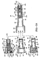
- leak detectors suitable for use in the subject system are illustrated.
- the system may utilize alternatively configured leak detectors 42, 44, 46 in conjunction with a common casing assembly 40.
- Mechanical leak detector assembly 42; optical leak detector assembly 44; and telemetry leak detector assembly 46 interchangeably couple with the casing assembly 40 to provide a flexible system that, depending on a customer's choice, different ways of monitoring oil leak through the first carcass of a double carcass hose may be achieved.
- three optional configurations for detecting leaks, assemblies 42, 44, 46, other types of leak detection devices may be employed (not shown) with the casing assembly 40 in addition thereto without departing from the invention.
- a forward pressure valve assembly 48 is disposed within a tubular rigid casing 50 of the casing assembly 40.
- the valve assembly 48 denies leaking fluid from the hose segment from accessing the leak detection assembly coupled to the casing 50 unless a prescribed pressure threshold is exceeded.
- the valve assembly 48 also prevents external water from migrating through the casing 50 and into the hose from the opposite direction.
- the casing 50 readily interchangeably couples with each variety of leak detection assembly 42, 44, 46 to meet the needs of the user as well as to facilitate replacement of malfunctioning detector components should the need arise.
- FIGS. 3B and 3C illustrate in exploded view the optical version leak detection assembly 44.
- the assembly forms a generally cylindrical device combining the leak detection assembly 44 and the casing assembly 40.
- An end plate 52 has an LED housing 54 projecting rearwardly therefrom.
- An LED circuit board 56 of a type available to the industry drives an LED 58 that fits within the housing 54,
- a long cycle battery 60 is disposed forward of the board 56 and rearward of transmitter circuit board 64.
- An O-ring seal 62 is disposed between the battery 60 and the board 64.
- the circuit board 64 is of a type commonly available and includes a micro-radio frequency transmitter and a micro-ultrasonic transmitter (in the telemetry version of the sensor assembly as shown in FIG. 2A and 2B) as well as optical signal generating circuitry (in the optical version of the sensor assembly).
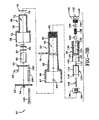
- the detection system is encapsulated into a casing 69, preferably although not necessarily formed of thermoplastic material.
- the casing 69 is generally cylindrical having a smaller diameter forward nose portion 70 and a larger diameter rearward head portion 74.
- a center axial passageway 72 projects through the casing 69 from end to end, beginning at an access orifice 76 at a forward end.
- An O-ring seal 78 is disposed forward and surrounds a forward end of the detector housing 69.
- the detector assembly 44 as well as the other two detector assembly versions 42, 46, are interchangeable, each being configured for insertion into the casing 50.
- Casing 50 is formed of a rigid material, preferably steel.
- the casing 50 is generally tubular and elongate, and includes a forward smaller diameter forward nose portion 80, an intermediate external screw threaded portion 82, a transverse assembly bore 84 adjacent the threaded portion 82, and a rearward enlarged head portion 86.
- the head portion 86 is formed to provide LED portals 88 sized to admit and retain an LED 58 as best seen in FIG. 3A.
- the casing 50 has an axial passageway 90 therethrough from end to end and an internally threaded forward end 92.
- a cylindrical optics support 94 formed of preferably thermoplastic material having a pair of rearwardly directed optics connector sockets 96, 98 and a transverse assembly bore extending therethrough.
- a pair of optics receiving passageways 102, 104 extend from a forward end of the support 94, through the support to respective sockets 96, 98.
- the passageways 102, 104 are sized to receive respective legs 108, 110 of optic fiber loop 106.
- the legs 108, 110 project through the support 94 to the sockets 96, 98. So located, the loop 106 projects forward from the support 94.
- An actuator member 112 is formed as cylindrical body 114 having central body cavity 115.
- a pair of tines 116 project rearward from the periphery of the body 114.
- a pin projection 118 is axially disposed on the central axis of body 114 and projects rearward.
- the pressure valve assembly 48 includes a generally tubular elongate body 120 formed of suitable material such as thermoplastic.
- the body 120 has a rearward enlarged cavity 122 dimensioned to receive the actuator body 114 therein.
- a forward elongate valve cavity 124 extends to an anterior chamber 126 at the forward end of the body 120.
- the valve cavity 124 communicates with the enlarged cavity 122 by means of relatively narrow passageway 128.
- External threaded portion 130 is located about the medial portion of body 120 and internal threaded surface 132 surrounds the anterior cavity 126.
- the cavity 124 is sized to seat first and second valve balls 134, 136 and a spring member 138 situated between the balls.
- An end retention screw 140 is provided and screws into the forward end of the body 120.
- the retention screw 140 has a small bore axial passageway 142 that extends into screw head 146, along the body of the screw to the cavity 124.
- the ball 136 seats against the internal opening of the passageway 142 and the ball 134 seats against the internal opening of the passageway 128.
- Spring 138 in compression nominally biases the balls 134, 136 against their respective openings with a preset level of force as will be explained below.
- An assembly pin 148 is further provided with a spacer sleeve 150 and a pin retainer 152.
- FIGS. 3B, 3C Assembly of the optical version 44 of the leak detection assembly will be readily appreciated from FIGS. 3B, 3C.
- the telemetry version of the leak detection assembly is shown in FIGS. 2A, 2B and incorporates signal transmission circuits that the optical version 44 does not require.
- the casing 69 receives the circuit board 64 therein until optical fiber sockets 66 protrude from opening 76.
- O-ring 78 mounts and seats over the forward end of the casing 69.
- Battery 60 inserts within the nose portion 70 of the body 69 followed by the LED electronics board 56.
- One or more signaling LEDs project out of board 56 and are aligned to reside within opening 75 of the casing 69.
- the end plate 52 encloses the rearward end of the body 69 and is secured by means of pin 148 extending through sleeve 150 to the retention cap 152.
- the assembly 44 is upon completion of assembly in condition for detachable coupling to the casing assembly 50.
- Casing assembly 40 is assembled by positioning the optical support body 94 within passageway 90, and securing the body 94 into position by the extension of pin 81 through the body transverse passage 100.
- the optical loop ends extend through passages 102, 104 respectively of the support body 94 to the sockets 96, 98.
- the actuation member 112 is inserted within the passage 90 and tines 114, 116 of the member 112 are positioned within the passageway 90 to abut body 94.
- the body 112 is received within chamber 122 of the pressure valve body 120 and pin projection 118 extends through passageway 128 to abut ball 134.
- the assembled optical detector assembly 44 couples to the casing assembly 40 by screw threaded attachment.
- optical connectors 66, 68 align with and enter into sockets 96, 98 respectively of the optics support body 94.
- an optical signal may be generated by electronic circuitry of board 64 and transmitted through the optical fiber loop 106.
- the forward end of the casing nose portion 70 upon reaching the terminal location within casing 80, will contact the support body 94 and push the body 94 forward. Such forward movement will cause pin projection 118 to move forward and move valve ball 134 forward. Ball 134 will thus be unseated, opening the passageway 128 between chambers 122, 124. Valve ball 136 remains seated against the passageway 142 through screw 140.
- the pressure valve by appropriate selection of screw 138, may be set to open at a low pressure, for example 90 psi. If the oil pressure exceeds the threshold, oil pressure will force ball 136 away from the internal opening of passageway 142 into an open position. Oil may then travel inside the cavity 124 through passageway 128 and cavity 122 to the internal chamber 115 of the body 112 wherein the optical loop 106 resides, Upon reaching the optical loop 106, the oil modifies the optical transmission properties of fiber. The electronic analysis of the optical transmission through the loop 106 determines an oil leak has occurred and the sensor starts the LED(s) 58.
- the occurrence and detection of a leak may further be stored as data within a passive RFID chip located on the board 56.
- Passive RFID chips that is requiring no energy source to function, are commonly available electronic devices. At the appropriate time, data stored inside the RFID chip may be retrieved as explained below.
- the sensor assembly 44 may be disconnected from the casing assembly 40 by threaded detachment. Upon disassociation of the sensor assembly 44 from the casing assembly 40, the spring 138 will release from compression to force ball 134 into sealing engagement with passageway 128. If the sensor assembly is in an underwater environment, water from outside of the sensor will thus be prevented from entering passageway 124 and proceeding therefrom out the forward end of passageway 142.
- the pressure valve assembly 48 accordingly operates to open to allow leaking oil to access the optical fiber 106 when a leak occur and to close whenever the leak detection assembly (42, 44, 46) is uncoupled from the casing assembly 40.
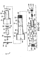
- FIGS. 3A and FIG. 5 show alternative mechanical versions of a leak detection assembly.
- the mechanical sensor assembly 154 of FIG. 5 includes a cylindrical body 156 having a sliding piston member 158 within an axial passageway 161.
- the piston 158 moves within the passageway between forward and rearward positions.
- a magneto 160 Secured to the piston is a magneto 160 that moves with the piston between the forward and rearward positions.
- a forward opening 162 extends through the forward end of body 156 and communicates with axial passage 161.
- a coil spring 164 surrounds the piston 158 within the body 156 and biases the sliding piston to the forward side of the passageway 161.
- the body 156 has external screw threads for coupling with the casing assembly 40 and a rubber end cap 168 that includes an axial air venting passageway that extends to chamber 161. If an oil leak occurs through the first carcass of a hose, the oil will move between the two carcasses until it reaches the forward end of the assembly 154. The oil forces the sliding piston 158 rearward and the magneto 160 moves rearward with the piston.
- the location of the magneto 160 may be externally determined by a reader and from the location of the magneto 160 a determination may be made that a leak has occurred. As described above with reference to the optical leak detection assembly 44, the occurrence and detection of a leak may further be stored as data within a passive RFID chip (not shown). Passive RFID chips, that is, requiring no energy source to function, are commonly available electronic devices. At the appropriate time, data stored inside the RFID chip may be retrieved as explained below.
- FIG. 3A shows an alternative configuration for a mechanical leak detector 42.
- the detector 42 includes a tubular body 170 having an axial passage 171.
- a piston 172 is slideably housed within passage 171 and moves between forward and rearward positions.
- a magneto 174 is secured to the piston 172 and moves therewith.
- An end plug 176 is located within a forward portion of passage 171 and includes a passageway 178.
- a sealing O-ring 180 is affixed about the plug 176 to seal off the passage 171.
- a coil spring 182 is situated within the passage 171 between a piston head 183 and end plate 52.
- a venting passageway 184 branches from passage 171 to a venting orifice 188 in the end plate 52.
- a valve ball 190 is positioned to seat against a lower segment 191 of the passageway 184 and is biased into a closed engagement by biasing spring 192.
- a sensor reader and data storage device 194 is shown schematically.
- the reader includes a read head 196 that is electrically connected to circuit board electronics 198 powered by batteries 200.
- the detection of movement rearward of the magneto 174 will be detected by head 196 and the electronic circuitry will cause an activation of LED indicator light 202.
- data indicative of the detection of a leak, an identification of the particular leak detection assembly detecting the leak may be stored in the device 194.
- the sensor reader and data storage device 194 provides a waterproof case, magnetic read head, electronic processor and data storage chip, long life battery and indicator LED.
- a wrist strap 204 may be provided for safely holding the unit.
- the inspector approximates the read head to the leak detector and the reader checks the RFID chip.
- the unit then reads and records the data stored in the RFID chip.
- the LED may be wired to flash to show the reading is completed.
- the data recorded in the reader may be downloaded into a computer system as part of the offshore hose line monitoring system. Such data may then be available through an internet or intranet website.
- the telemetry leak detection assembly 46 may likewise be used in conjunction with the casing assembly 40 as will be appreciated from FIGS. 3A, 2A and 2B0.
- Assembly 46 is constructed similar to assembly 44 in that optical fiber connectors 66, 68 protrude forward from optics circuit board 64.
- An O-ring seal 62 renders a storage compartment waterproof for a battery 60.
- Electronics board 56 controls the operation of micro-ultrasonic transmitter 57 and micro-radio transmitter 59.
- Sensing the presence of a leak with the telemetry assembly unit 46 is a described above with regard to the optical assembly 44.
- the presence of oil surrounding fiber 106 will cause optical properties of the fiber 106 to change. The change is detected and interpreted as evidencing a leak.
- the transmitters 57,59 may then transmit data to a remote receiver identifying by means of a passive RFID chip within the assembly 46 the location of the leak, hose identification data, etc.
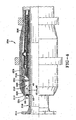
- a double carcass hose 204 is depicted consisting of an inner carcass 206, an outer carcass 208 extending to a carcass forward end 210, and a collection space 212 between the carcass layers 206,208.
- a connector 214 is affixed to each end of the hose 204 and includes a nipple or sleeve 216 that is positioned along the axial inner surface of the inner carcass 206.
- An elongate fluid collection housing 218 is positioned to extend along the outside of the connector sleeve 216 parallel with the axis of the hose 204.
- the housing 218 includes annular anchoring beads 220 that mechanically connects the duct into the outer carcass layer 208 proximate forward end 210.
- the housing 218 is shown to include a top wall 222 and a forward end wall 224.
- a sensor assembly 42, 44, 46 coupled to casing assembly 40 mounts preferably although not necessarily in the end wall 224 of the housing 218.
- the senor (42, 44, or 46) within casing assembly 40 is intended to protrude through the wall 224 of the housing 218.
- the sensor head portion 86 remains outside of the housing 218 as the sensor is affixed by means of screw threads 82 into a threaded aperture within wall 224. So positioned the transmission elements 57, 59 are outside of the mounting wall 224.
- the sensing element 42, 44, or 46 projects into the housing 224 and the optical fiber (or plural fibers) 106, within the casing assembly 40 resides within the housing 224. While one housing 224 and one sensor assembly 42, 44, 46/casing assembly 40 is shown in FIG. 4, a plurality of sensors may be positioned about the periphery of the hose, each coupling with a respective housing 224.
- fluid leakage from the inner carcass 206 or water entering the hose as a result of a breach in the outer carcass 208, will migrate into the collection space 212, eventually reaching and entering the forward end of the sensor 42, 44, 46/casing assembly 40.
- the pressure valve assembly 48 will open when the pressure of the fluid against the valve assembly exceeds a pressure threshold.
- the pressure valve assembly 48 opens fluid will enter into the axial passageway through the casing assembly 40 until reaching the optical fiber loop(s) 106.
- the escaping oil, or water will contact the fiber 106.
- Contact between the fiber outer coating and the fluid will alter the transmission properties carried by the fiber 106 and be interpreted by the optical electronics circuitry mounted on board 64 as a leak.
- the electronics will then initiate a change in communication signal to indicate a breach by means of the ultrasonic transmitter 57 and/or the RF transmitter 59.
- a visual indicator change at signaling LED 58 will occur.
- the mechanical leak detector 42 is deployed, the mechanical detector will change position and indicate the existence of a leak to the sensor reader 194.
- the optical sensing element 106 is passive, and does not have or need an active energy supply, making the element 106 intrinsically safer when contacting oil than other forms of sensing devices.
- the wall 224 through which the sensor 42, 44, or 46 mounts thus functionally isolates the passive sensing element 106 from the battery powered analysis element 56 and transmission elements 57, 59.
- the system is relatively light and occupies minimal space. The replacement of a malfunctioning sensor is readily facilitated by removing the end plate of the sensing unit. Substitution of one sensor type (42, 44, 46) for a different sensor type is also readily facilitated in like manner should a malfunction occur or the needs of the user change.
- the optical fiber operates as a contacting medium for detecting the presence of fluid and is a reliable means for detecting the presence and identity of fluid in the space 212.
- the analysis element 56 is powered by durable long duration battery 60.
- the element 56 operates continuously without need for a timer and functions preferably using artificial intelligence or neural network software.
- the transmission elements 57, 59 include built-in replaceable batteries and ID chips. When data is collected and transmitted, the identity of the sensor/hose segment is provided with the data to a remote receiver. Corrective action to repair the leaking hose can then be taken.
- the transmission elements 57,59 work under magnetic principle with no electrical contacts.
Landscapes
- Physics & Mathematics (AREA)
- General Physics & Mathematics (AREA)
- Examining Or Testing Airtightness (AREA)
Applications Claiming Priority (1)
| Application Number | Priority Date | Filing Date | Title |
|---|---|---|---|
| US11/486,583 US7509841B2 (en) | 2006-07-14 | 2006-07-14 | Flexible leak detection system and method for double carcass hose |
Publications (3)
| Publication Number | Publication Date |
|---|---|
| EP1879008A2 true EP1879008A2 (de) | 2008-01-16 |
| EP1879008A3 EP1879008A3 (de) | 2008-05-21 |
| EP1879008B1 EP1879008B1 (de) | 2009-12-30 |
Family
ID=38617421
Family Applications (1)
| Application Number | Title | Priority Date | Filing Date |
|---|---|---|---|
| EP07013805A Not-in-force EP1879008B1 (de) | 2006-07-14 | 2007-07-13 | Flexibles System und Verfahren zum Erkennen von Undichtigkeiten für einen Schlauch mit doppelter Karkasse |
Country Status (6)
| Country | Link |
|---|---|
| US (1) | US7509841B2 (de) |
| EP (1) | EP1879008B1 (de) |
| CN (1) | CN101105263B (de) |
| AT (1) | ATE453855T1 (de) |
| BR (1) | BRPI0703136A (de) |
| DE (1) | DE602007004030D1 (de) |
Cited By (3)
| Publication number | Priority date | Publication date | Assignee | Title |
|---|---|---|---|---|
| EP2270379A4 (de) * | 2008-03-28 | 2017-08-23 | The Furukawa Electric Co., Ltd. | Fluidförderrohr und fluidleckageerfassungssystem |
| GB2587444A (en) * | 2019-03-15 | 2021-03-31 | Caterpillar Inc | Device for detecting an oil leak |
| EP3940363A4 (de) * | 2019-03-12 | 2022-05-18 | The Yokohama Rubber Co., Ltd. | Flüssigkeitsleckdetektor für meeresschlauch |
Families Citing this family (26)
| Publication number | Priority date | Publication date | Assignee | Title |
|---|---|---|---|---|
| US8960071B2 (en) | 2004-08-18 | 2015-02-24 | Waters Technologies Corporation | Piston pump with leak diagnostic port |
| WO2006023526A2 (en) * | 2004-08-18 | 2006-03-02 | Waters Investments Limited | Defined leak path for high pressure seal |
| US8104327B1 (en) * | 2006-09-27 | 2012-01-31 | C.G.R.S. Inc. | Leak detection method for a primary containment system |
| US7461541B2 (en) * | 2006-09-27 | 2008-12-09 | C.G.R.S., Inc | Leak detection method for a primary containment system |
| EP1953517B1 (de) * | 2007-02-05 | 2016-07-13 | Nexans | Anordnung zur Überwachung der Dichtigkeit eines evakuierten Raums |
| US7918126B2 (en) * | 2007-09-26 | 2011-04-05 | Fmc Technologies, Inc. | Intelligent underwater leak detection system |
| WO2009120087A1 (en) * | 2008-03-27 | 2009-10-01 | Tool-Tech As | Liquid flow measuring during buoy-loading |
| US20090301778A1 (en) * | 2008-06-05 | 2009-12-10 | Baker Hughes Incorporated | Method and system for tracking lubricant leakage from downhole drilling equipment |
| GB201009042D0 (en) | 2010-06-01 | 2010-07-14 | Dunlop Oil & Marine Ltd | Leak detector |
| US9291521B2 (en) | 2010-12-30 | 2016-03-22 | Eaton Corporation | Leak detection system |
| US8528385B2 (en) | 2010-12-30 | 2013-09-10 | Eaton Corporation | Leak detection system |
| US8708554B2 (en) | 2011-05-12 | 2014-04-29 | Arrowhead Products Corporation | Leak detection apparatus for aircraft bleed air systems |
| USD694140S1 (en) * | 2012-04-27 | 2013-11-26 | Eaton Corporation | Hose and sensor assembly |
| USD712769S1 (en) * | 2012-08-22 | 2014-09-09 | Eaton Corporation | Sensor housing for hydraulic hose |
| US9341316B2 (en) * | 2012-09-19 | 2016-05-17 | Robert J. Novak | Leak detection, containment and cuttoff system for a pipeline or other conduit |
| FR3011903B1 (fr) * | 2013-10-14 | 2016-01-01 | Techlam Sas | Joint flexible pour conduites d'hydrocarbure, procede de detection de fuite dans un tel joint, et systeme de detection de fuite d'hydrocarbure dans un tel joint. |
| USD739506S1 (en) | 2014-06-27 | 2015-09-22 | Eaton Corporation | Sensor enclosure assembly for a hose |
| USD755938S1 (en) | 2014-06-27 | 2016-05-10 | Eaton Corporation | Sensor enclosure assembly for a hose |
| CN104075855B (zh) * | 2014-07-23 | 2016-04-06 | 西安优耐特容器制造有限公司 | 一种管接头泄露检测装置 |
| US10337948B2 (en) * | 2016-02-18 | 2019-07-02 | Solaredge Technologies Ltd | Method and apparatus for hermeticity test |
| CN108019621A (zh) * | 2016-10-28 | 2018-05-11 | 宁波乐惠国际工程装备股份有限公司 | 一种化学品泄漏检测装置 |
| JP7389313B2 (ja) * | 2018-12-18 | 2023-11-30 | 横浜ゴム株式会社 | マリンホースの流体漏れ検知システム |
| US11879568B2 (en) | 2019-01-04 | 2024-01-23 | Canadian Pressure Control Inc. | Pipeline-leak-containment apparatus |
| GB201913740D0 (en) * | 2019-09-24 | 2019-11-06 | Ge Oil & Gas Uk Ltd | End fitting apparatus and method |
| CN111122077B (zh) * | 2020-01-06 | 2024-08-27 | 长江勘测规划设计研究有限责任公司 | 装配在rov上的摄像与灯光的联动装置及其工作方法 |
| CN113309613B (zh) * | 2021-05-25 | 2022-06-10 | 中国商用飞机有限责任公司 | 气体泄漏探测件、气体泄漏探测组件、引气管路结构和飞机 |
Family Cites Families (88)
| Publication number | Priority date | Publication date | Assignee | Title |
|---|---|---|---|---|
| US2250496A (en) | 1937-06-22 | 1941-07-29 | Hartford Nat Bank & Trust Co | Pressure measuring device |
| US2759175A (en) | 1954-03-12 | 1956-08-14 | Thomas R Spalding | Leak detector for pipe joint |
| GB1039515A (en) | 1962-07-24 | 1966-08-17 | Power Aux Ies Ltd | Improvements in or relating to flexible pressure tubes and ducts |
| US3800217A (en) | 1971-09-23 | 1974-03-26 | Lowrance Electronics Mfg | Pipeline including means of indicating the existence of and location of a leak |
| US3834235A (en) | 1971-12-17 | 1974-09-10 | M Bouton | Liquid and solid sensing device |
| IT989115B (it) | 1973-06-13 | 1975-05-20 | Treg Spa | Impianto galleggiante per carico e scarico di prodotti petroliferi e simili |
| GB1503502A (en) | 1974-04-19 | 1978-03-15 | Dunlop Ltd | Flexible hose lines |
| US4270049A (en) | 1978-06-12 | 1981-05-26 | Ishikawajima-Harima Jukogyo Kabushiki Kaisha | Liquid leakage detection system |
| JPS54163423A (en) | 1978-06-14 | 1979-12-26 | Bridgestone Tire Co Ltd | Reinforced rubber hose |
| NL7904597A (nl) | 1978-06-14 | 1979-12-18 | Bridgestone Tire Co Ltd | Slang voor het overbrengen van een fluidum. |
| US4446892A (en) | 1979-09-05 | 1984-05-08 | Maxwell Ag | Method and apparatus for monitoring lengths of hose |
| DK148638B (da) | 1979-11-15 | 1985-08-19 | Avon Rubber Co Ltd | Organ til detektering af laekager fra roerledninger |
| US4286464A (en) | 1980-01-14 | 1981-09-01 | Technical Development Company | Optical fluid level monitor |
| GB2117479B (en) | 1982-03-23 | 1985-07-17 | Dunlop Ltd | Improvements in or relating to flexible hose |
| GB2117480B (en) | 1982-03-23 | 1985-07-03 | Dunlop Ltd | Improvements in or relating to flexible hose |
| GB2138917B (en) | 1983-04-27 | 1986-09-17 | Dunlop Ltd | Flexible hose |
| US4689484A (en) | 1985-05-17 | 1987-08-25 | Mcmahon Robert L | Photoelectric leak detection system for double-walled tanks and the like |
| JPS61280541A (ja) | 1985-06-05 | 1986-12-11 | Power Reactor & Nuclear Fuel Dev Corp | 液体漏洩検出方法 |
| US4630490A (en) | 1985-07-12 | 1986-12-23 | Carron & Company | Compression strain gauge transducer assembly |
| US5022045A (en) | 1985-08-06 | 1991-06-04 | Elliott Stanley B | Optical-type, phase transition humidity-responsive devices |
| US4638132A (en) | 1985-10-28 | 1987-01-20 | Lectron Products, Inc. | Electrical pressure switch |
| GB8603364D0 (en) | 1986-02-11 | 1986-03-19 | Dunlop Ltd | Hose leak detectors |
| US4851817A (en) | 1986-03-10 | 1989-07-25 | Brossia Charles E | Fiber optic probe system |
| US5005005A (en) | 1986-03-10 | 1991-04-02 | Brossia Charles E | Fiber optic probe system |
| US4764671A (en) | 1986-10-03 | 1988-08-16 | Kollmorgen Corporation | Fiber optic fluid sensor using coated sensor tip |
| US4834497A (en) * | 1987-02-27 | 1989-05-30 | The United States Of American As Represented By The United States Department Of Energy | Fiber optic fluid detector |
| LU86877A1 (fr) * | 1987-05-13 | 1988-06-13 | Euratom | Bouee marine servant de relais bidirectionnel entre une capsule sous-marine emettrice-receptrice de signaux ultrasonores et une base terrestre |
| US4932257A (en) | 1987-10-01 | 1990-06-12 | Webb Michael C | Double wall piping system |
| EP0383864A1 (de) | 1988-07-08 | 1990-08-29 | Rib Loc Group Limited | Vorrichtung und verfahren zum erkennen und zum kontrollieren von leckagen in rohrleitungen |
| US4922232A (en) | 1988-10-21 | 1990-05-01 | Bosich Joseph F | Leakage containment and detection systems |
| US4961069A (en) | 1988-12-07 | 1990-10-02 | Aeroquip Corporation | Dual optical level monitor |
| US5553971A (en) | 1988-12-20 | 1996-09-10 | Intelpro Corporation | Double-containment underground piping system |
| US5172730A (en) | 1989-07-03 | 1992-12-22 | Insituform Of North American, Inc. | Two-wall leakage detection system for a pipe |
| US6000434A (en) | 1989-09-11 | 1999-12-14 | Dayco Products, Inc. | Flexible hose construction and method of making the same |
| US5129428A (en) | 1989-09-11 | 1992-07-14 | Dayco Products, Inc. | Flexible hose constuction |
| JPH03148028A (ja) | 1989-11-02 | 1991-06-24 | Matsushita Electric Ind Co Ltd | 圧電型圧力センサ |
| US5265465A (en) | 1990-04-16 | 1993-11-30 | Coretank, Inc. | Secondary containment and dual leak detection system |
| US5058420A (en) | 1990-04-20 | 1991-10-22 | Hughes Aircraft Company | Fiber optic liquid leak detector |
| US5267670A (en) | 1990-08-31 | 1993-12-07 | Dayco Products, Inc. | Fuel dispensing system having a flexible hose with a static dissipator and a fuel leak detector and method of making the same |
| US5102012A (en) | 1990-08-31 | 1992-04-07 | Dayco Products, Inc. | Fuel dispensing system having a flexible hose with a static dissipater and a fuel leak detector |
| US5090871A (en) | 1991-02-12 | 1992-02-25 | Systems Chemistry, Inc. | Junction assembly with leak detection means |
| US5176025A (en) | 1991-02-19 | 1993-01-05 | E. O. Butts Consultants Ltd. | Pipeline secondary containment system and method |
| US5187366A (en) | 1991-06-25 | 1993-02-16 | Joram Hopenfeld | Sensors for detecting leaks |
| US5200615A (en) | 1991-06-25 | 1993-04-06 | Joram Hopenfeld | Method and apparatus for detecting the presence of fluids |
| US5323142A (en) | 1991-07-17 | 1994-06-21 | Dresser Industries, Inc. | Accessory for detecting leaking of safety valves |
| US5291032A (en) | 1991-08-21 | 1994-03-01 | Hughes Aircraft Company | Fiber optic evanescent wave fuel gauge and leak detector using eccentric core fibers |
| JP3380567B2 (ja) | 1991-10-04 | 2003-02-24 | 株式会社ブリヂストン | 漏洩検知ホース |
| EP0553686B1 (de) | 1992-01-29 | 1997-10-22 | The Yokohama Rubber Co., Ltd. | Druckfester Schlauch |
| US5343736A (en) | 1992-06-15 | 1994-09-06 | Systems Chemistry, Inc. | Optical leak sensor and position detector |
| US5279157A (en) | 1992-08-03 | 1994-01-18 | Casco Products Corporation | Liquid level monitor |
| JP3170656B2 (ja) | 1992-11-09 | 2001-05-28 | 横浜ゴム株式会社 | ホース |
| GB2274498B (en) | 1993-01-26 | 1996-10-02 | Dunlop Ltd | Improvements in and relating to floatable flexible hose |
| US5452076A (en) | 1993-09-29 | 1995-09-19 | Optiguard, Inc. | Fluid detection system |
| US5399876A (en) | 1994-03-03 | 1995-03-21 | Simmonds Precision Products, Inc. | Optical point level sensor with lens |
| IT1266168B1 (it) | 1994-07-15 | 1996-12-23 | Manuli Rubber Ind Srl | Tubo flessibile a doppia carcassa |
| US5551484A (en) | 1994-08-19 | 1996-09-03 | Charboneau; Kenneth R. | Pipe liner and monitoring system |
| JPH08261861A (ja) | 1995-03-27 | 1996-10-11 | Mitsubishi Heavy Ind Ltd | 油配管用フレキシブルチューブ |
| US5650564A (en) | 1995-06-08 | 1997-07-22 | Wodeslavsky; Josef | Fluid drip detection system |
| DE19604821C1 (de) | 1996-02-10 | 1997-10-02 | Michael Hesky Gmbh | Vorrichtung zur Leckerfassung bei Rohrleitungen |
| DE29608551U1 (de) * | 1996-05-12 | 1996-07-25 | Sailer, Josef, 87474 Buchenberg | Meßvorrichtung mit absenkbarer Meßsonde, insbesondere für Grundwassermessungen |
| US5714681A (en) | 1996-05-14 | 1998-02-03 | Furness; Robert L. | Double carcass hose failure detection system |
| JPH1061900A (ja) | 1996-08-12 | 1998-03-06 | Tamada Kogyo Kk | 埋設管の漏洩検知構造 |
| US5828798A (en) | 1996-09-09 | 1998-10-27 | Hopenfeld; Joram | Looped fiber-optic sensor for the detection of substances |
| US6026862A (en) | 1997-02-14 | 2000-02-22 | Ameron International Corporation | Double containment pipe sections |
| US6032699A (en) | 1997-05-19 | 2000-03-07 | Furon Company | Fluid delivery pipe with leak detection |
| US6082392A (en) | 1997-09-30 | 2000-07-04 | General Transervice, Inc. | Dual hose assembly and control system for truck-to-truck fuel transfer |
| US6328074B1 (en) | 1997-11-13 | 2001-12-11 | Petrotechnik Limited | Pipe for conveying fluids such as petroleum products |
| US5905194A (en) | 1997-11-21 | 1999-05-18 | Strong; Thomas P. | Pipe line with integral fault detection |
| EP0952378B1 (de) | 1998-04-23 | 2006-05-31 | The Yokohama Rubber Co., Ltd. | Schlauch zum Befördern einer Flüssigkeit |
| JP3982908B2 (ja) | 1998-05-18 | 2007-09-26 | 横浜ゴム株式会社 | マリンホース損傷検知用損傷検知装置 |
| DE19848015A1 (de) | 1998-10-17 | 2000-04-20 | Ion Secara | Automatisches Dekompressionsventil |
| US6129107A (en) | 1999-03-16 | 2000-10-10 | Jackson; Robert W. | Fluid-containment hose |
| SE522010C2 (sv) * | 1999-03-17 | 2004-01-07 | Dart Engineering Ag | Anordning vid snabbkopplingsdel anslutningsbar till system med trycksättningsbart media samt sådan snabbkopplingsdel |
| US6386237B1 (en) | 1999-04-12 | 2002-05-14 | The Goodyear Tire & Rubber Company | Abrasive material transport hose with wear detecting sensors |
| US6149032A (en) * | 1999-04-16 | 2000-11-21 | Tokheim Corporation | Electro-mechanical piston meter |
| US6498991B1 (en) | 1999-10-01 | 2002-12-24 | The Goodyear Tire & Rubber Company | Process and apparatus for monitoring a physical condition of a hose |
| US6305427B1 (en) | 1999-11-19 | 2001-10-23 | Kenway Corporation | Double walled apparatus and methods |
| DE50005023D1 (de) | 1999-11-23 | 2004-02-19 | Phoenix Ag | Doppelwandiger schlauch mit leckanzeigevorrichtung |
| US6374852B1 (en) | 2000-08-09 | 2002-04-23 | Brightvalve, Llc | Leak arresting valve |
| GB0110223D0 (en) | 2001-04-26 | 2001-06-20 | Sensor Highway Ltd | Method and apparatus for leak detection and location |
| US6688338B2 (en) | 2001-12-26 | 2004-02-10 | Paul Meli | Secondary containment system for pipelines |
| US6550499B1 (en) | 2002-02-08 | 2003-04-22 | Taiwan Semiconductor Manufacturing Co., Ltd | Detectable liquid leakage conduit |
| US7860680B2 (en) * | 2002-03-07 | 2010-12-28 | Microstrain, Inc. | Robotic system for powering and interrogating sensors |
| DE10231135A1 (de) | 2002-07-10 | 2004-01-29 | Robert Bosch Gmbh | Druckentlastungsventil |
| JP2004239612A (ja) | 2003-02-03 | 2004-08-26 | Bridgestone Corp | 液漏れ検知ホース |
| US20040177891A1 (en) | 2003-03-11 | 2004-09-16 | Spaolonzi Mauricio Pinto | Leak detection system and method for offshore hose lines |
| US8565959B2 (en) | 2004-12-03 | 2013-10-22 | The Goodyear Tire & Rubber Company | Method for detection of low leak rates in a tire |
| US7213611B2 (en) | 2004-12-15 | 2007-05-08 | Eaton Corporation | Valve assembly |
-
2006
- 2006-07-14 US US11/486,583 patent/US7509841B2/en active Active
-
2007
- 2007-07-06 BR BRPI0703136-0A patent/BRPI0703136A/pt not_active IP Right Cessation
- 2007-07-13 DE DE602007004030T patent/DE602007004030D1/de active Active
- 2007-07-13 AT AT07013805T patent/ATE453855T1/de not_active IP Right Cessation
- 2007-07-13 EP EP07013805A patent/EP1879008B1/de not_active Not-in-force
- 2007-07-16 CN CN2007101364630A patent/CN101105263B/zh not_active Expired - Fee Related
Cited By (5)
| Publication number | Priority date | Publication date | Assignee | Title |
|---|---|---|---|---|
| EP2270379A4 (de) * | 2008-03-28 | 2017-08-23 | The Furukawa Electric Co., Ltd. | Fluidförderrohr und fluidleckageerfassungssystem |
| EP3940363A4 (de) * | 2019-03-12 | 2022-05-18 | The Yokohama Rubber Co., Ltd. | Flüssigkeitsleckdetektor für meeresschlauch |
| GB2587444A (en) * | 2019-03-15 | 2021-03-31 | Caterpillar Inc | Device for detecting an oil leak |
| US11054333B2 (en) | 2019-03-15 | 2021-07-06 | Caterpillar Inc. | Device for detecting an oil leak |
| GB2587444B (en) * | 2019-03-15 | 2023-05-17 | Caterpillar Inc | Device for detecting an oil leak |
Also Published As
| Publication number | Publication date |
|---|---|
| ATE453855T1 (de) | 2010-01-15 |
| CN101105263B (zh) | 2011-10-19 |
| US7509841B2 (en) | 2009-03-31 |
| DE602007004030D1 (de) | 2010-02-11 |
| US20080011056A1 (en) | 2008-01-17 |
| EP1879008B1 (de) | 2009-12-30 |
| EP1879008A3 (de) | 2008-05-21 |
| BRPI0703136A (pt) | 2008-02-26 |
| CN101105263A (zh) | 2008-01-16 |
Similar Documents
| Publication | Publication Date | Title |
|---|---|---|
| EP1879008B1 (de) | Flexibles System und Verfahren zum Erkennen von Undichtigkeiten für einen Schlauch mit doppelter Karkasse | |
| EP1879007B1 (de) | Sensorsystem und Verfahren zum Erkennen von Undichtigkeiten für einen Schlauch mit doppelter Karkasse | |
| US7453367B2 (en) | Leak detection system and method for offshore hose lines | |
| US4775855A (en) | Hose leak detectors | |
| CN109661500B (zh) | 用于指梁闩锁组件的传感器 | |
| CA3164163C (en) | Modular sensing device, system, and method | |
| US7938179B2 (en) | Method of using a charged chamber pressure transmitter for subterranean tools | |
| CN112539894A (zh) | 船舶用软管的流体泄漏感测系统 | |
| EP1460408A1 (de) | System und Verfahren zur Leckdetektion für Schlauchleitungen auf See | |
| CN107810332A (zh) | 使用光学测量的蓄能器容量检测器 | |
| US4576037A (en) | Leak detectors | |
| KR20110030735A (ko) | 상수도관 누수 측정장치 | |
| KR102494760B1 (ko) | 조명을 이용한 고장 진단 시스템이 내장된 수중로봇 | |
| CN219348853U (zh) | 甲烷传感器 | |
| EP4563876A1 (de) | Gehäuse und kappenanordnung für einen meeresschlauchflüssigkeitsleckdetektor und meeresschlauchflüssigkeitsleckdetektionssystem | |
| EP3847094A1 (de) | Verfahren zur prüfung der wasserdichtigkeit von instrumenten zur verwendung unter wasser | |
| GB2138956A (en) | Improvements in or relating to leak detectors | |
| WO2023079819A1 (ja) | マリンホースの流体漏れ検知システムおよびその製造方法 | |
| IT202100000062U1 (it) | Dispositivo di misura e monitoraggio per bombole o condutture contenenti fluidi in pressione |
Legal Events
| Date | Code | Title | Description |
|---|---|---|---|
| PUAI | Public reference made under article 153(3) epc to a published international application that has entered the european phase |
Free format text: ORIGINAL CODE: 0009012 |
|
| AK | Designated contracting states |
Kind code of ref document: A2 Designated state(s): AT BE BG CH CY CZ DE DK EE ES FI FR GB GR HU IE IS IT LI LT LU LV MC MT NL PL PT RO SE SI SK TR |
|
| AX | Request for extension of the european patent |
Extension state: AL BA HR MK YU |
|
| PUAL | Search report despatched |
Free format text: ORIGINAL CODE: 0009013 |
|
| AK | Designated contracting states |
Kind code of ref document: A3 Designated state(s): AT BE BG CH CY CZ DE DK EE ES FI FR GB GR HU IE IS IT LI LT LU LV MC MT NL PL PT RO SE SI SK TR |
|
| AX | Request for extension of the european patent |
Extension state: AL BA HR MK RS |
|
| RIC1 | Information provided on ipc code assigned before grant |
Ipc: G01M 3/38 20060101AFI20071031BHEP |
|
| RAP1 | Party data changed (applicant data changed or rights of an application transferred) |
Owner name: VEYANCE TECHNOLOGIES, INC. |
|
| 17P | Request for examination filed |
Effective date: 20080819 |
|
| 17Q | First examination report despatched |
Effective date: 20080924 |
|
| AKX | Designation fees paid |
Designated state(s): AT BE BG CH CY CZ DE DK EE ES FI FR GB GR HU IE IS IT LI LT LU LV MC MT NL PL PT RO SE SI SK TR |
|
| GRAP | Despatch of communication of intention to grant a patent |
Free format text: ORIGINAL CODE: EPIDOSNIGR1 |
|
| GRAS | Grant fee paid |
Free format text: ORIGINAL CODE: EPIDOSNIGR3 |
|
| GRAA | (expected) grant |
Free format text: ORIGINAL CODE: 0009210 |
|
| AK | Designated contracting states |
Kind code of ref document: B1 Designated state(s): AT BE BG CH CY CZ DE DK EE ES FI FR GB GR HU IE IS IT LI LT LU LV MC MT NL PL PT RO SE SI SK TR |
|
| REG | Reference to a national code |
Ref country code: GB Ref legal event code: FG4D |
|
| REG | Reference to a national code |
Ref country code: CH Ref legal event code: EP |
|
| REG | Reference to a national code |
Ref country code: IE Ref legal event code: FG4D |
|
| REF | Corresponds to: |
Ref document number: 602007004030 Country of ref document: DE Date of ref document: 20100211 Kind code of ref document: P |
|
| PG25 | Lapsed in a contracting state [announced via postgrant information from national office to epo] |
Ref country code: SE Free format text: LAPSE BECAUSE OF FAILURE TO SUBMIT A TRANSLATION OF THE DESCRIPTION OR TO PAY THE FEE WITHIN THE PRESCRIBED TIME-LIMIT Effective date: 20091230 Ref country code: LT Free format text: LAPSE BECAUSE OF FAILURE TO SUBMIT A TRANSLATION OF THE DESCRIPTION OR TO PAY THE FEE WITHIN THE PRESCRIBED TIME-LIMIT Effective date: 20091230 Ref country code: FI Free format text: LAPSE BECAUSE OF FAILURE TO SUBMIT A TRANSLATION OF THE DESCRIPTION OR TO PAY THE FEE WITHIN THE PRESCRIBED TIME-LIMIT Effective date: 20091230 |
|
| LTIE | Lt: invalidation of european patent or patent extension |
Effective date: 20091230 |
|
| PG25 | Lapsed in a contracting state [announced via postgrant information from national office to epo] |
Ref country code: SI Free format text: LAPSE BECAUSE OF FAILURE TO SUBMIT A TRANSLATION OF THE DESCRIPTION OR TO PAY THE FEE WITHIN THE PRESCRIBED TIME-LIMIT Effective date: 20091230 Ref country code: PL Free format text: LAPSE BECAUSE OF FAILURE TO SUBMIT A TRANSLATION OF THE DESCRIPTION OR TO PAY THE FEE WITHIN THE PRESCRIBED TIME-LIMIT Effective date: 20091230 Ref country code: LV Free format text: LAPSE BECAUSE OF FAILURE TO SUBMIT A TRANSLATION OF THE DESCRIPTION OR TO PAY THE FEE WITHIN THE PRESCRIBED TIME-LIMIT Effective date: 20091230 |
|
| PG25 | Lapsed in a contracting state [announced via postgrant information from national office to epo] |
Ref country code: AT Free format text: LAPSE BECAUSE OF FAILURE TO SUBMIT A TRANSLATION OF THE DESCRIPTION OR TO PAY THE FEE WITHIN THE PRESCRIBED TIME-LIMIT Effective date: 20091230 |
|
| PG25 | Lapsed in a contracting state [announced via postgrant information from national office to epo] |
Ref country code: ES Free format text: LAPSE BECAUSE OF FAILURE TO SUBMIT A TRANSLATION OF THE DESCRIPTION OR TO PAY THE FEE WITHIN THE PRESCRIBED TIME-LIMIT Effective date: 20100410 Ref country code: PT Free format text: LAPSE BECAUSE OF FAILURE TO SUBMIT A TRANSLATION OF THE DESCRIPTION OR TO PAY THE FEE WITHIN THE PRESCRIBED TIME-LIMIT Effective date: 20100430 Ref country code: EE Free format text: LAPSE BECAUSE OF FAILURE TO SUBMIT A TRANSLATION OF THE DESCRIPTION OR TO PAY THE FEE WITHIN THE PRESCRIBED TIME-LIMIT Effective date: 20091230 Ref country code: BG Free format text: LAPSE BECAUSE OF FAILURE TO SUBMIT A TRANSLATION OF THE DESCRIPTION OR TO PAY THE FEE WITHIN THE PRESCRIBED TIME-LIMIT Effective date: 20100330 Ref country code: IS Free format text: LAPSE BECAUSE OF FAILURE TO SUBMIT A TRANSLATION OF THE DESCRIPTION OR TO PAY THE FEE WITHIN THE PRESCRIBED TIME-LIMIT Effective date: 20100430 Ref country code: RO Free format text: LAPSE BECAUSE OF FAILURE TO SUBMIT A TRANSLATION OF THE DESCRIPTION OR TO PAY THE FEE WITHIN THE PRESCRIBED TIME-LIMIT Effective date: 20091230 |
|
| PG25 | Lapsed in a contracting state [announced via postgrant information from national office to epo] |
Ref country code: SK Free format text: LAPSE BECAUSE OF FAILURE TO SUBMIT A TRANSLATION OF THE DESCRIPTION OR TO PAY THE FEE WITHIN THE PRESCRIBED TIME-LIMIT Effective date: 20091230 Ref country code: BE Free format text: LAPSE BECAUSE OF FAILURE TO SUBMIT A TRANSLATION OF THE DESCRIPTION OR TO PAY THE FEE WITHIN THE PRESCRIBED TIME-LIMIT Effective date: 20091230 Ref country code: CZ Free format text: LAPSE BECAUSE OF FAILURE TO SUBMIT A TRANSLATION OF THE DESCRIPTION OR TO PAY THE FEE WITHIN THE PRESCRIBED TIME-LIMIT Effective date: 20091230 |
|
| PG25 | Lapsed in a contracting state [announced via postgrant information from national office to epo] |
Ref country code: CY Free format text: LAPSE BECAUSE OF FAILURE TO SUBMIT A TRANSLATION OF THE DESCRIPTION OR TO PAY THE FEE WITHIN THE PRESCRIBED TIME-LIMIT Effective date: 20091230 Ref country code: GR Free format text: LAPSE BECAUSE OF FAILURE TO SUBMIT A TRANSLATION OF THE DESCRIPTION OR TO PAY THE FEE WITHIN THE PRESCRIBED TIME-LIMIT Effective date: 20100331 |
|
| PLBE | No opposition filed within time limit |
Free format text: ORIGINAL CODE: 0009261 |
|
| STAA | Information on the status of an ep patent application or granted ep patent |
Free format text: STATUS: NO OPPOSITION FILED WITHIN TIME LIMIT |
|
| 26N | No opposition filed |
Effective date: 20101001 |
|
| PG25 | Lapsed in a contracting state [announced via postgrant information from national office to epo] |
Ref country code: DK Free format text: LAPSE BECAUSE OF FAILURE TO SUBMIT A TRANSLATION OF THE DESCRIPTION OR TO PAY THE FEE WITHIN THE PRESCRIBED TIME-LIMIT Effective date: 20091230 |
|
| PG25 | Lapsed in a contracting state [announced via postgrant information from national office to epo] |
Ref country code: IE Free format text: LAPSE BECAUSE OF NON-PAYMENT OF DUE FEES Effective date: 20100713 |
|
| REG | Reference to a national code |
Ref country code: GB Ref legal event code: 732E Free format text: REGISTERED BETWEEN 20111006 AND 20111012 |
|
| PG25 | Lapsed in a contracting state [announced via postgrant information from national office to epo] |
Ref country code: MT Free format text: LAPSE BECAUSE OF FAILURE TO SUBMIT A TRANSLATION OF THE DESCRIPTION OR TO PAY THE FEE WITHIN THE PRESCRIBED TIME-LIMIT Effective date: 20091230 |
|
| REG | Reference to a national code |
Ref country code: DE Ref legal event code: R082 Ref document number: 602007004030 Country of ref document: DE Representative=s name: DREISS PATENTANWAELTE, DE |
|
| REG | Reference to a national code |
Ref country code: CH Ref legal event code: PL |
|
| REG | Reference to a national code |
Ref country code: DE Ref legal event code: R082 Ref document number: 602007004030 Country of ref document: DE Representative=s name: DREISS PATENTANWAELTE PARTG MBB, DE Effective date: 20120125 Ref country code: DE Ref legal event code: R081 Ref document number: 602007004030 Country of ref document: DE Owner name: TRELLEBORG INDUSTRI AB, SE Free format text: FORMER OWNER: VEYANCE TECHNOLOGIES, INC., FAIRLAWN, OHIO, US Effective date: 20120125 |
|
| PG25 | Lapsed in a contracting state [announced via postgrant information from national office to epo] |
Ref country code: LI Free format text: LAPSE BECAUSE OF NON-PAYMENT OF DUE FEES Effective date: 20110731 Ref country code: CH Free format text: LAPSE BECAUSE OF NON-PAYMENT OF DUE FEES Effective date: 20110731 |
|
| REG | Reference to a national code |
Ref country code: NL Ref legal event code: SD Effective date: 20120709 |
|
| REG | Reference to a national code |
Ref country code: FR Ref legal event code: TP Owner name: TRELLEBORG INDUSTRI AB, SE Effective date: 20120731 |
|
| PG25 | Lapsed in a contracting state [announced via postgrant information from national office to epo] |
Ref country code: HU Free format text: LAPSE BECAUSE OF FAILURE TO SUBMIT A TRANSLATION OF THE DESCRIPTION OR TO PAY THE FEE WITHIN THE PRESCRIBED TIME-LIMIT Effective date: 20100701 Ref country code: LU Free format text: LAPSE BECAUSE OF NON-PAYMENT OF DUE FEES Effective date: 20100713 |
|
| PG25 | Lapsed in a contracting state [announced via postgrant information from national office to epo] |
Ref country code: TR Free format text: LAPSE BECAUSE OF FAILURE TO SUBMIT A TRANSLATION OF THE DESCRIPTION OR TO PAY THE FEE WITHIN THE PRESCRIBED TIME-LIMIT Effective date: 20091230 |
|
| PGFP | Annual fee paid to national office [announced via postgrant information from national office to epo] |
Ref country code: NL Payment date: 20130703 Year of fee payment: 7 Ref country code: DE Payment date: 20130703 Year of fee payment: 7 Ref country code: MC Payment date: 20130704 Year of fee payment: 7 |
|
| PGFP | Annual fee paid to national office [announced via postgrant information from national office to epo] |
Ref country code: GB Payment date: 20130704 Year of fee payment: 7 Ref country code: FR Payment date: 20130725 Year of fee payment: 7 |
|
| PGFP | Annual fee paid to national office [announced via postgrant information from national office to epo] |
Ref country code: IT Payment date: 20130719 Year of fee payment: 7 |
|
| REG | Reference to a national code |
Ref country code: DE Ref legal event code: R119 Ref document number: 602007004030 Country of ref document: DE |
|
| REG | Reference to a national code |
Ref country code: NL Ref legal event code: V1 Effective date: 20150201 |
|
| GBPC | Gb: european patent ceased through non-payment of renewal fee |
Effective date: 20140713 |
|
| PG25 | Lapsed in a contracting state [announced via postgrant information from national office to epo] |
Ref country code: NL Free format text: LAPSE BECAUSE OF NON-PAYMENT OF DUE FEES Effective date: 20150201 |
|
| REG | Reference to a national code |
Ref country code: FR Ref legal event code: ST Effective date: 20150331 |
|
| PG25 | Lapsed in a contracting state [announced via postgrant information from national office to epo] |
Ref country code: IT Free format text: LAPSE BECAUSE OF NON-PAYMENT OF DUE FEES Effective date: 20140713 Ref country code: DE Free format text: LAPSE BECAUSE OF NON-PAYMENT OF DUE FEES Effective date: 20150203 |
|
| REG | Reference to a national code |
Ref country code: DE Ref legal event code: R119 Ref document number: 602007004030 Country of ref document: DE Effective date: 20150203 |
|
| PG25 | Lapsed in a contracting state [announced via postgrant information from national office to epo] |
Ref country code: FR Free format text: LAPSE BECAUSE OF NON-PAYMENT OF DUE FEES Effective date: 20140731 Ref country code: GB Free format text: LAPSE BECAUSE OF NON-PAYMENT OF DUE FEES Effective date: 20140713 |
|
| PG25 | Lapsed in a contracting state [announced via postgrant information from national office to epo] |
Ref country code: MC Free format text: LAPSE BECAUSE OF NON-PAYMENT OF DUE FEES Effective date: 20140731 |