EP1879025B1 - Regenerierbare Membraneinheit für Fluss Feld-Flussfraktionierung und diese enthaltendes Kanalmodul - Google Patents
Regenerierbare Membraneinheit für Fluss Feld-Flussfraktionierung und diese enthaltendes Kanalmodul Download PDFInfo
- Publication number
- EP1879025B1 EP1879025B1 EP06014275.9A EP06014275A EP1879025B1 EP 1879025 B1 EP1879025 B1 EP 1879025B1 EP 06014275 A EP06014275 A EP 06014275A EP 1879025 B1 EP1879025 B1 EP 1879025B1
- Authority
- EP
- European Patent Office
- Prior art keywords
- membrane
- flow
- channel
- channel module
- fff
- Prior art date
- Legal status (The legal status is an assumption and is not a legal conclusion. Google has not performed a legal analysis and makes no representation as to the accuracy of the status listed.)
- Ceased
Links
Images



Classifications
-
- G—PHYSICS
- G01—MEASURING; TESTING
- G01N—INVESTIGATING OR ANALYSING MATERIALS BY DETERMINING THEIR CHEMICAL OR PHYSICAL PROPERTIES
- G01N30/00—Investigating or analysing materials by separation into components using adsorption, absorption or similar phenomena or using ion-exchange, e.g. chromatography or field flow fractionation
- G01N30/0005—Field flow fractionation
-
- B—PERFORMING OPERATIONS; TRANSPORTING
- B01—PHYSICAL OR CHEMICAL PROCESSES OR APPARATUS IN GENERAL
- B01D—SEPARATION
- B01D67/00—Processes specially adapted for manufacturing semi-permeable membranes for separation processes or apparatus
- B01D67/0002—Organic membrane manufacture
- B01D67/0004—Organic membrane manufacture by agglomeration of particles
- B01D67/00046—Organic membrane manufacture by agglomeration of particles by deposition by filtration through a support or base layer
-
- B—PERFORMING OPERATIONS; TRANSPORTING
- B01—PHYSICAL OR CHEMICAL PROCESSES OR APPARATUS IN GENERAL
- B01D—SEPARATION
- B01D71/00—Semi-permeable membranes for separation processes or apparatus characterised by the material; Manufacturing processes specially adapted therefor
- B01D71/02—Inorganic material
- B01D71/024—Oxides
- B01D71/027—Silicium oxide
-
- B—PERFORMING OPERATIONS; TRANSPORTING
- B01—PHYSICAL OR CHEMICAL PROCESSES OR APPARATUS IN GENERAL
- B01D—SEPARATION
- B01D2325/00—Details relating to properties of membranes
- B01D2325/02—Details relating to pores or porosity of the membranes
- B01D2325/022—Asymmetric membranes
- B01D2325/0231—Dense layers being placed on the outer side of the cross-section
-
- B—PERFORMING OPERATIONS; TRANSPORTING
- B01—PHYSICAL OR CHEMICAL PROCESSES OR APPARATUS IN GENERAL
- B01D—SEPARATION
- B01D2325/00—Details relating to properties of membranes
- B01D2325/22—Thermal or heat-resistance properties
Definitions
- the present invention relates to a membrane unit for a flow field-flow fractionation apparatus, and, more particularly, to a membrane unit for a flow field-flow fractionation apparatus comprising a regenerable membrane.
- the present invention further relates to a channel module comprising such a membrane unit; a field-flow fractionation unit comprising such a channel module; an analytical apparatus containing such a field-flow fractionation unit and a GPC unit; and the use of a heat-resistant membrane in a channel for field-flow fractionation.
- the channel module may be used in field-flow fractionation (FFF) and preferably in the flow field-flow fractionation (flow FFF) for the separation (purification) and concentration of particle-containing liquid samples.
- the invention is especially suitable for use in symmetric and asymmetric flow FFF, which are both sub-techniques of the FFF group of separation techniques.
- Field-flow fractionation is a group of chromatography-like separation techniques for the separation of particles in liquids.
- the principle of FFF is outlined in detail below.
- the particle sample is transported into and through a separation channel by means of a suitable liquid carrier.
- the separation of the different particle samples is achieved by an external separation field, which is applied perpendicular to the main flow direction of the channel.
- Particles in this context mean any sort of molecules, especially macromolecules such as proteins, polymers, biopolymers, but also colloids and small molecules without size limitation.
- the differently sized particle fractions are eluted from the FFF channel at different times (retention times) after the initial injection, and are transferred directly into one or more on-line detection systems for quantitation and qualification of the samples.
- FFF sub-techniques use the same basic separation channel principle. However, the construction of the channel may vary, as different external separation fields are used in the various FFF sub-techniques.
- electrical field gradient a temperature gradient, a flow field or a centrifugal field
- the FFF sub-technique is called electrical FFF, thermal FFF, symmetric or asymmetric flow FFF or centrifugal/sedimentation FFF.
- the FFF channel has to meet certain requirements.
- the channel is constructed as a module (hereinafter referred to as "channel module"), where the actual channel cavity used for the separation is located inside this module.
- channel module modules
- these cavities typically have a length of about 20-30cm, a width of about 2-3 cm and a thickness of about 70-500 ⁇ m. In principle other cavities of smaller and larger dimensions can be also used.
- the channel cavity thickness in FFF is selected to be sufficiently small so that a laminar flow profile is present inside the channel. Together with the externally applied separation field, this laminar flow profile is necessary for successful FFF separations. At the currently given temperature and solvent viscosity ranges used in FFF, the thickness can only be expanded to about 1000 ⁇ m since above this limit a laminar flow profile can no longer be established.
- a channel thickness smaller than 50-70 ⁇ m is limited by technical and material restrictions since the channel cavity has to be very flat and homogenous throughout its entire length. This cannot be achieved below 50-70 ⁇ m any longer to a sufficient extent by currently available materials and manufacturing conditions.
- FFF channel module takes place inside this channel cavity.
- construction of such a FFF channel module can be carried out in various ways. This depends very much on the FFF sub-technique for which the channel module is used. One possibility for such a channel module is described hereinafter with respect to Fig. 5 .
- a channel module 20 comprises an upper plate (top part) 6, a lower plate (bottom part) 1, a membrane 5, a support 4 and a spacer 10.
- the upper plate 6 is provided with inlet ports 7, 8, 9 for the main channel flow, focus flow, and cross flow, respectively, and the lower plate 1 is provided with an outlet port 3 for the cross flow.
- the nature of the spacer 10 determines the length, width and thickness of a channel cavity 2 which is provided in the lower plate 1.
- the spacer 10 can be made from flat sheets of different materials, e.g. Mylar (polyester), inside which the inner channel cavity 11 is formed.
- An asymmetric flow FFF device is known from the publication entitled “ Separation and Quantitation of Monoclonal Antibody Aggregates by Asymmetrical Flow Field-Flow Fractionation and Comparison to Gel Permeation Chromatography", by A. Litzén et al., Analytical Biochemistry 212, 469-480 (1993 ).
- the device comprises a channel assembly with a porous frit (filter for smallest particles), a membrane, a spacer, and an upper wall.
- a flow field-flow fractionation system including a typical separation channel which comprises (from bottom to top) an outlet frit, a sheet like disposable filtration membrane, a channel spacer and an inlet frit within a channel housing is disclosed in US 6,365,050 .
- Another flow field-flow fractionation apparatus is disclosed in US 4,147,621 .
- the separation channel used in this apparatus basically corresponds to the separation channel of the flow field-flow fractionation system disclosed in US 6,365,050 .
- no sheet like disposable filtration membranes as described in US 6,365,050 are applied.
- Suitable paper based or other sheet like disposable filtration membranes were not available at that time and the filtration membranes used in the flow field-flow fractionation apparatus disclosed in US 4,147,621 were instead freshly prepared on the porous polypropylene plates forming the lower and the upper channel wall. However, it is not suggested in any of these references that the membrane can or should be regenerable.
- US 2005/0148064 discloses a microfluidic device and a method for fractionating and/or trapping selected molecules with a diffusion barrier or a porous membrane.
- the dimensions of the microfluidic device are such that it may, for example, be integrated as a structure for a "lab-on-a-chip" (cf. paragraph [0035] of US 2005/0148064 ).
- One object of the present invention is to improve flow field-flow fractionation (flow FFF), in the direction of better and easier handling, decreased running costs, and to access new, additional fields of application.
- flow FFF flow field-flow fractionation
- a further object of the present invention is to significantly increase the separation performance and reproducibility of the measurement results.
- the present invention provides in one of its various aspects a membrane unit for a field-flow fractionation apparatus according to claim 1, a channel module for a field-flow fractionation apparatus according to claim 4, a field-flow fractionation unit according to claim 5, as well as the use of a regenerable membrane in a channel module for field-flow fractionation according to claim 6.
- a membrane unit for a field-flow fractionation apparatus according to claim 1 a channel module for a field-flow fractionation apparatus according to claim 4
- a field-flow fractionation unit according to claim 5 as well as the use of a regenerable membrane in a channel module for field-flow fractionation according to claim 6.
- Optional and preferred features are defined in the dependent claims.
- a membrane unit for a flow field-flow fractionation apparatus comprising a regenerable membrane.
- regenerable it is understood that the membrane can be regenerated (cleaned) after its performance has dropped to unacceptable levels, and can then be used again with essentially the same performance as the original membrane.
- this regeneration process is repeatable at least 10 times, more preferably 100 times or more, and most preferably 1000 times or more.
- a heat-resistant membrane is used, which may or may not be, but preferably is regenerable.
- heat-resistant means resistant at temperatures of at least 90°C, preferably between 150 and 200°C.
- the membrane unit according to both embodiments of the present invention may consist only of the membrane, but preferably the membrane unit further comprises a porous support.
- the membrane and the porous support together form an integral "monolithic" membrane unit.
- the membrane unit consists of the support and at least one membrane.
- the porosity of the membrane and the porous support, respectively, may be the same or different.
- the support is preferably a frit. If the support and the membrane form one integral membrane unit, no separate insertion of a membrane into a channel module is necessary during assembly.
- the support and the membrane, which together form the membrane unit are made of at least one material which is chemically inert with respect to the solvents and samples used for the measurement. More preferably, the material(s) have a temperature resistance and mechanical stability sufficient for use in field-flow fractionation at temperatures of 90°C or higher.
- the membrane and membrane support according to the present invention can be cleaned in-between the measurements and, thus, can be used repeatedly.
- the membrane unit of the preferred monolithic embodiment of the present invention can be placed directly into a channel module, and together with the module into any existing flow FFF system as an integrally formed "monolithic" unit.
- the monolithic design reduces the risk of alterations of the FFF measurement results and also the generation of wrong and artefact-containing measurements, which can be caused by the insufficient reproducibility of the currently used membrane units.
- the selection of special, well-suited materials for the membrane and the membrane support provides the required inert properties during the separation process on the one hand and at the same time the easy and reversible cleaning possibilities on the other hand.
- Preferred materials for the support and the membrane are selected from the group consisting of inorganic materials, polymeric materials, metallic materials or glass-based materials, or any combination thereof.
- the inorganic material is selected from the group consisting of metallic oxides, in particular aluminum oxide, and metallic silicates, in particular aluminum silicate.
- the polymeric material preferably comprises a fluoropolymer, in particular a thermoplastic fluoropolymer, most preferably a polytetrafluoroethylene (PTFE, sold under Teflon®) or a mixture of PTFE and another suitable polymer such as polyethersulfone (PES).
- Suitable metallic materials include stainless steel and titanium.
- the effective pore size of the membrane support is typically between 1 ⁇ m und 100 ⁇ m. Due to this, the membrane support can be produced by using particle sizes which are typical standard sizes of these materials, used for the production of the support. This simplifies the production on the one hand and allows a sufficiently high flow rate across the membrane support, avoiding additional back pressures. As an alternative to the use of sintered porous materials, the use of specially woven ultra-thin stainless steel webs with pore sizes in the ⁇ m-range is also possible.
- a possible further embodiment of the present invention is the use of additional membrane layers between the support and the membrane itself, wherein all layers are fixed to each other.
- This design would be especially well suited if the device is intended to be used not only in FFF but also for other applications, e.g. as membrane testing apparatus, for the investigation of the basic processes which occur during a filtration experiment and for testing the surface chemistry of specially developed substances.
- membranes having several layers and an anisotropic design are often required.
- Another aspect of the present invention is a channel module for a field-flow fractionation apparatus with a separation membrane.
- the membrane which is regenerable and/or heat-resistant, may be permanently fixed to the membrane support.
- This monolithic part is completely made of inert inorganic, metallic or inert polymeric materials, which can be regenerated and cleaned after use.
- This embodiment is particularly suitable to achieve the objectives mentioned above.
- completely inert materials for the membrane it is possible to avoid a complete disassembly of the channel for membrane replacement between the measurement sequences, which is necessary in conventional field-flow fractionation units. This saves costs during the operation of the system (work time and membrane material), facilitates the use of the system and opens up a new range of applications, such as high-temperature FFF applications, which could not be accomplished by FFF before.
- Regeneration of the membrane after use has proven to be superior over frequent exchanges of the membranes.
- Regeneration in this context means the cleaning process of the membrane surface and pores to remove all or at least substantially all impurities.
- the regeneration has to be conducted in such a way that the membrane after regeneration shows the same physical properties, such as surface charge, pore-size distribution, etc. as a new completely unused membrane.
- the cleaning process is achieved by pumping a special solution through the channel, without disassembly.
- different chemicals at room temperature or at an elevated temperature can be used.
- Possible cleaning agents for polar hydrophilic impurities can be strongly alkaline solutions containing NaOH, KOH and additional detergents, such as sodium dodecylsulfate (SDS), or strong acidic solutions.
- additional detergents such as sodium dodecylsulfate (SDS), or strong acidic solutions.
- strong organic solvents such as THF, can be employed.
- THF trifluoride
- rinsing with a washing solvent ethanol, or methanol
- the effective pore size of a membrane ideally suited for the channel module described in this invention ranges from 1 nm to about 500 nm. This is also the typical pore size range of the replaceable membranes used for conventional channel modules. However, the membranes of the channel modules according to this aspect of the present invention have the advantage that they can be cleaned and regenerated.
- the actually used pore size depends greatly on the desired application and the used FFF instrument.
- the typical pore size used in Flow FFF, for example, is in the range between 1 and 10 nm.
- FFF membranes described in this invention can be additionally modified by chemical derivatization since they consist of inert porous materials which can be regenerated.
- regenerable membrane as used in the present invention is preferably chemically inert, semi-permeable and heat-resistant.
- porous support material are stainless steel and inorganic ceramic materials, particularly such based on alumina and/or silica.
- the porous support material can be cut directly from a piece of a suitable raw material (starting material), or it can be built up stepwise by adding different porous layers one on top of each other. After that a wet, inert and porous material can be cast on top of this support material to form the membrane. This is followed by the reversible drying/sintering of the wet material in such a way that it is directly and permanently connected with the support material.
- This manufacturing process is advantageous since the separation membrane can be directly generated on the support material.
- the membrane is strongly bonded and permanently connected to the support material. Additionally, this production technology has the advantage that very thin membranes can be produced, which are mechanically still very stable since they are bonded with a strong support material.
- the wet membrane material can be transferred to the surface of the support material by deposition, ideally by using liquid deposition, by a spinning process or by vapour deposition. These techniques provide a very homogenous thickness of the wet material on the surface. This is essential to achieve a membrane having the same properties along its entire surface.
- the preferred material used in such a membrane formation process is an inorganic ceramic material, particularly a ceramic based on alumina and/or silica.
- the present invention allows that the membrane unit with the regenerable membrane can be used repeatedly for field-flow fractionation, and also at high temperatures if the membrane unit is heat-resistant. Using this process, the membrane can be completely chemically regenerated at high temperatures in-between two FFF runs or in-between two sequences of runs. The membrane is no longer a consumable part which needs to be replaced on a frequent basis, but is a fixed part of the membrane module which can be regenerated when necessary.
- the process of regeneration by heating or by cleaning with special chemicals removes adsorbed impurities from the membrane and reinstates the original surface conditions of the membrane, which have been defined by the selection of the membrane material and/or chemical modification of the membrane surface.
- the present invention provides a channel module for a field-flow fractionation apparatus comprising the above membrane unit.
- the membrane of the membrane unit forms one accessible side of the channel module.
- the arrangement of the porous membrane at an accessible side simplifies access to the membrane. Accordingly, the design of the interfaces to the field flow fractionation unit becomes easier and the cleaning is simplified.
- the present invention provides a field-flow fractionation unit which comprises the above channel module.
- This field-flow fractionation unit can be used as a stand-alone apparatus to separate molecules in a particle-containing liquid sample.
- the present invention may provide a field-flow fractionation method using the above-described channel module. This method is carried out at temperatures of 90°C or higher. Preferably, the method is carried out at temperatures between approximately 150 and 200°C. It is particularly preferred that this method is a flow field-flow fractionation (flow FFF) method.
- flow FFF flow field-flow fractionation
- the present invention provides the use of a channel module comprising a membrane unit with a regenerable membrane for field-flow fractionation.
- the field-flow fractionation is carried out at temperatures of 90°C or higher.
- the invention provides an easy-to-use device for field-flow fractionation. Preferred is the use of the FFF system together with a flow measurement and control device (not shown).
- the membrane unit is constructed from different single parts 4, 5, as shown in Fig. 5 .
- the membrane unit is formed integrally ( Figs. 1 and 4 ).
- the membrane unit of this invention can be used together with the channel module which is described in DE 198 08 992 A .
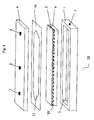
- Fig. 4 shows an FFF channel module 20 which comprises a massive support 4 on which a semi-permeable membrane 5 is positioned.
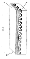
- the membrane 5 and the support 4 such as a frit, are preferably provided as an integrally formed part and constitute a membrane unit 30 (shown in detail in Fig. 1 ).
- On top of the membrane 5 a thin slide 10, the so-called spacer, is located.
- the thin slide 10 has a cavity 11 inside, which constitutes the actual separation channel.
- the separation channel 11 height is determined by the thickness of this spacer 10.
- the separation channel 11 has a trapezoidal shape with apexes at inlet and outlet ports 7, 9 provided in a top part 6 of the channel module 20.
- the top of the channel module 20 is a first flat plate (top part) 6, in which the inlet port 7, an injection port 8 and the outlet port 9 are located.
- the channel module 20 further comprises a second flat plate 1 as a bottom part.
- the bottom part 1 has a cavity 2 formed on one side of the plate 1, into which the membrane unit 30 is to be placed.
- an outlet port 3 which is in fluid communication with the cavity 2 is provided in the lower plate 1.
- the channel top and bottom 1, 6 may be made of glass, plastic, stainless steel, and the spacer 10 may be made of a mechanically and chemically stable, but still flexible plastic material.
- the membrane unit 30 is preferably made as one piece, which greatly simplifies the assembly of the complete FFF device.
- the high-temperature resistant membrane 5 and the support 4 may also be provided as separate parts.
- the massive support 4 and the membrane 5 are made of a porous material.
- the porosity of the support 4 and the membrane 5 differ significantly.
- the support 4 preferably has an effective pore size in the range of 1-100 ⁇ m, but in most cases 10-20 ⁇ m is used.
- the preferred thickness of the support 4 ranges from ca. 100 ⁇ m to 1 cm.
- the average pore size (porosity) of the membrane 5 is preferably from 1 to 500 nm. In most cases a porosity of 1 to 10 nm and a thickness of some 100 ⁇ m are used.
- the boundary layers of the support 4 and membrane 5 are fully co-planar to each other.
- the design could also be changed so that the two components are no longer located co-planar to each other.
- the membrane 5 and support 4 have the same surface dimensions. This has the advantage that they can be made from a single piece as well.
- the currently preferred combination of materials uses stainless steel for the support 4 and a mix of stainless steel and inorganic materials (mix of Al 2 O 3 , SiO 2 , TiO 2 and ZrO 2 ) for the membrane 5. Depending on the intended use, these materials can be changed to better suited combinations. However, to ensure the required inert and heat-resistant properties of the channel module 30, it is advisable to use only raw materials based on inorganic and/or metallic and/or Teflon® and/or glass materials.
- the membrane 5 can also be used for several other applications, when a chemical surface modification is carried out by derivatization.
- a chemical surface modification is carried out by derivatization.
- One example is the separation of amphiphilic and cationic polymers und particles, which irreversibly adsorb onto conventional membranes with negative surface charge.
- the channel module 20 has to be chemically treated in such a way that the complete surface of the membrane 5 is modified from negative to positive charges. These positive surface charges of the membrane 5 prevent the positively charged analytes from adsorbing.
- the starting material can be Al 2 O 3 or a stainless steel frit with a suitable porosity. This material would act as support 4 and can have a thickness starting from about 100 ⁇ m to 10 millimetres, preferably 200 ⁇ m to 3 mm.
- the membrane 5 can be coated on said support 4 by e.g. applying a suspension of an organic binder (e.g. a dispersion of polyacrylate or another suitable polymer) and inorganic particles, e.g. SiO 2 particles, by using, for example, a vibration coating device or a spray head.
- an organic binder e.g. a dispersion of polyacrylate or another suitable polymer
- inorganic particles e.g. SiO 2 particles
- the particle size has to be selected depending on the porosity of the membrane 5 to be produced.
- the thickness of such a membrane layer is typically between 10 to 400 ⁇ m, preferably 10 to 100 ⁇ m.
- the inorganic particles and the support material 4 are bonded together by the organic binder.
- This binder is then evaporated and decomposed using high temperatures in an oven.
- the inorganic material e.g. SiO 2
- the membrane 5 and the support 4 are irreversibly bonded together.
- the temperatures in the oven should be selected in such a way that the sintering process is just beginning to start. It should be ensured that the sintering temperature is not too high, and that the temperature is not applied too long, so that a sufficient porosity is still maintained. On the other hand, the temperature should be selected high enough and should be applied long enough to ensure a sufficiently durable connection between the layers. Depending on the materials used, the temperature can be in the range of 800 to 1200°C. Other temperatures can also be used if the above-mentioned requirements are fulfilled.
- FIG. 1 a membrane unit 30 is shown, wherein the membrane 5 has a gradually decreasing pore size from the support 4 towards the topmost layer of the membrane 5.
- the membrane 5 consists of a polymer material such as PTFE that cannot be easily coated onto the support, other suitable techniques such as sputtering or electrode deposition can be used.
- a field-flow fractionation membrane unit, produced by the above-described process, can be easily cleaned, for example by chemical regeneration with alkalic or acidic solutions containing detergents and/or with strong organic solvents such as THF.
- This field-flow fractionation membrane unit can be used in a new process for repeated FFF measurements, wherein the membrane 5 can be chemically regenerated between successive FFF measurements.
- HFFFF field-flow fractionation unit for use at high temperatures
- the basic set-up is similar to the construction of typical asymmetric field flow fractionation units such as, for instance, described by K.-G. Wahlund et al., "Application of an Asymmetrical Flow Field-Flow Fractionation Channel to the Separation and Characterization of Proteins, Plasmids, Plasmid Fragments, Polysaccharides and Unicellular Algae", Journal of Chromatography 461 (1989) 73-87 .
- These conventional units are not suitable for use at high temperatures. In order to be able to use the asymmetric field flow fractionation technology at high temperatures, several technical changes have to be performed on such units.
- the high temperature FFF channel module 20, comprising the high-temperature resistant membrane 5, is the key part of an FFF unit which may be used at high temperatures, and is one aspect of the invention.
- the channel module 20 is, for instance, made of stainless steel and ceramics.
- the top and bottom walls 6, 1 are constructed as shown in Fig. 4 .
- the top wall 6 is made of high-grade stainless steel which withstands not only high temperatures but also aggressive chemical solvents, such as TCB (trichlorobenzene).
- the top part 6 is provided with the inlet port 7 for the main channel flow, the inlet port 8 for the focus flow, and the outlet port 9 for the separated sample exiting to detector units 43, 44 ( Fig. 2 ) or 45 ( Fig. 3 ), respectively.
- the bottom wall 1 is also made of high-grade stainless steel material, and is provided with the cavity 2 comprising the outlet port 3, where the cross flow can exit the channel module 20.
- the cavity 2 is made as a compartment where the support 4, such as a porous frit, is positioned.
- the porous frit 4 is made of ceramics, or more preferably, high-grade stainless steel. It is important that the thermal expansion coefficients of the top and bottom walls 6, 1 of the channel module 20, the frit 4 and all other parts of the channel module 20 are the same or at least very similar. This avoids damage and material tensions inside the channel at higher temperatures, when the materials are expanding.
- the high temperature resistant FFF membrane 5 is positioned on top of the stainless steel frit 4.
- the FFF membrane 5 may be made of a very thin porous stainless support (not shown) onto which a ceramic membrane is cast.
- the thickness of the support can be about 50 to 250 ⁇ m.
- the thin stainless steel support prevents breaking of the ceramic membrane 5, so as to be sufficiently stable at high temperature conditions.
- the ceramic membrane 5 can also be directly cast onto the upper surface of the porous stainless steel frit 4, which is located in the compartment 2 of the bottom wall 1 of the channel module 20.
- the ceramic membrane 5 used determines the cut-off and has a pore size of typically 1 to 10 nm or a cut-off of typically 1 to 100 kDa.
- the ceramic membrane 5 cast on the porous stainless steel support is normally very thin with a typical thickness of 50 to 150 ⁇ m. In total, the thickness of the ceramic membrane 5, including the thin stainless steel support, is preferably between approximately 100 to 400 ⁇ m.
- the ceramic membrane 5 can be symmetric or asymmetric. Symmetric means that the pore size dimensions are homogeneous throughout the ceramic layer and asymmetric means that the pore sizes decrease from the bottom to the top of the ceramic layer.
- the high-temperature resistant spacer 10 is placed between the bottom 1 of the channel module 20, including the porous stainless steel frit 4 covered by the ceramic membrane 5, and the top 6 of the channel module 20.
- the spacer 10 can be made of any material which withstands high temperatures (90°C or more) on the one hand and which allows sufficient sealing on the other hand. Suitable materials for the spacer 10 are, for instance, Mylar® (polyester) and stainless steel.
- the HTFFF channel module 20 is placed inside a temperature controlled chamber 41, as shown in Figs. 2 and 3 .
- the solvent delivery from a solvent reservoir 34 is accomplished by means of a total of two pumps 31, 32.
- the first pump 31 is used for the delivery of the channel flow and injection of a sample, and the second pump 32 enables focusing of the sample before elution.
- a third pump 33 controls the cross-flow out of the lower channel compartment 1. All three pumps 31, 32, 33 are located outside the temperature chamber 41, and the second and third pumps 32 and 33 are directly connected via capillaries 135b, 136b to the channel module 20 inside the heated chamber 41.
- the outcoming flow from pump 33 is directed to a waste bottle 35 via capillary 136a and is collected therein.
- the solvent from the solvent reservoir 34 is preheated by first directing capillaries 134a, 135a through the heated chamber 41, after which the solvent is delivered back to the channel flow and focus pumps 31, 32.
- the channel flow pump 31 is first connected to a temperature-controlled injection channel module 42 via capillary 134b. Sample injection is accomplished via a temperature controlled manual injection valve or preferably by means of a heated autosampler such as the injection channel module 42. After leaving the injection channel module 42, the flow passes through a heated transfer capillary 137 and into the heated chamber 41. The channel flow pump 31 feeds the sample to the injection port 7 of the channel module 20 ( Fig. 4 ).
- Each detector unit 43, 44, 45 may comprise one or more single detectors.
- US Patents Nos. 6,192,764 and 6,109,119 it is possible to ensure stable baselines since no back-flushing step is-needed, and the focus-flow is introduced via a capillary 138 to an extra port 8 (see Fig. 4 ) preferably in the middle of the channel module 20, and is not directed through the detector unit(s) 43, 44, 45 into the channel module 20.
- detector unit 43 is also placed inside the temperature-controlled chamber 41.
- the exiting capillary 139a from the channel module outlet port 9 is directly connected to the detector unit 43, which typically are IR, RI, MALS, LALS or viscometry type detectors, respectively.
- the detector unit 43 typically are IR, RI, MALS, LALS or viscometry type detectors, respectively.
- a heated transfer capillary 139b can be employed.
- the last detector in the flow path is connected to a waste reservoir 36.
- the total system is controlled by computer software, which enables the use of single runs or complete run sequences.
- the software controls the pumps 31, 32, 33, the autosampler (injection device) 42, and the detector units 43, 44, 45. It allows the acquisition and evaluation of data, including the calculation of molar masses and radiuses. Further detectors of other manufacturers can be used with the system and are controlled by the specific software supplied for these detectors.
- HFFFF field-flow fractionation for use at high temperatures
- the solvent bottle 34 is connected via fluid capillary 134a to the pump 31, which feeds the main channel flow (injection flow) to the high temperature injection channel module 42.
- the solvent bottle 34 is also connected to the second pump 32, which delivers the focus flow via capillary 138 into the focus flow inlet port 8.
- a separation by means of an field-flow fractionation using the focus technology as disclosed in US patents Nos. 6,192,764 and 6,109,119 is subdivided into two steps, i.e. focusing and elution.
- the first step is to inject and focus the sample inside the channel module 20.
- the pump 31 is actuated and flushes the sample out of the high temperature injection system 42 through the heated transfer capillary 137 into the high temperature FFF channel module 20, which is mounted inside the heated chamber 41.
- the pump 32 starts to deliver solvent to the channel module 20, and the cross flow control pump 33 limits the out-coming cross flow of the channel module 20.
- the out-coming flow of the cross flow control module or pump 33 passes to the waste bottle 35.
- the several flow rates of the channel flow pump 31, the focus flow pump 32 and the cross flow control pump 33 are calculated by a software, so that a part of the flow exits the channel module 20 into the capillary 139a and subsequently into the detector unit 43.
- the flow passes through the heated transfer capillary 139b to the external detector unit 44, which may be provided in addition to the detector unit 43.
- the configuration of the detector unit 44 depends on the desired information about the sample. Different numbers and types of detectors may be used.
- the last detector 44 in this embodiment is connected to the waste bottle 36.
- the elution modus starts.
- the pump 32 now stops, reducing the focus flow.
- pump 31 increases the flow rate of the channel flow to achieve a constant flow out of the channel module 20 to the detector units 43, 44.
- the sample inside the heated channel module 20 elutes out of the channel module 20 and passes the detectors 43, 44.
- the data acquisition and the timing of the system are carried out by the cross flow control module (pump) 33, which is connected to a personal computer (not shown).
- the cross flow control module (pump) 33 which is connected to a personal computer (not shown).
- the flow rates of the pump 31 and the cross flow control pump 33 remain constant to guarantee a constant flow to the detectors 43, 44 until the software starts the next injection of a sample.
- the solvent bottle 34 is connected via fluid capillary 134a to the pump 31, which delivers the main channel flow (injection flow) to the high temperature injection channel module 42, which is a part of an existing high temperature GPC channel module 46.
- the solvent bottle 34 is also connected to the second pump 32, which delivers the focus flow via capillary 138 into the inlet port 8 for the focus flow.
- the separation by means of field-flow fractionation using the focus technology as disclosed in US Patents Nos. 6,192,764 and 6,109,119 is subdivided into two steps. The first step is to inject and focus the sample inside the channel module 20.
- the pump 31 is operated and flushes the sample out of the high temperature injection system 42 through a heated transfer capillary 139 into the high temperature FFF channel module 20, which is mounted inside the heated chamber 41.
- the pump 32 starts to feed solvent to the channel module 20, and the cross flow control module 33 limits the out-coming cross flow of the channel module 20.
- the out-coming flow of the cross flow control module 33 flows into the waste bottle 35.
- the several flow rates of the channel flow pump 31, the focus flow pump 32 and the cross flow control module 33 are calculated by a software, so that part of the flow exits the channel module 20 through the heated transfer capillary 139 into the detector unit 45 containing one or several detectors of the existing high temperature GPC unit 46.
- the configuration of the detector unit 45 depends on the desired information about the sample. Different numbers and types of detectors may be provided.
- the last detector in line is connected to the waste bottle 36.
- the elution modus starts.
- the pump 32 now stops, reducing the focus flow.
- pump 31 increases the flow rate of the channel flow to achieve a constant flow out of the channel module 20 and into the detector unit 43.
- the sample inside the heated channel module 20 elutes out of the channel module 20 and passes the detector unit 43.
- the data acquisition and the timing of the system are carried out by the cross flow control module 33, which is connected to a personal computer (not shown).
- the flow rates of the pump 31 and the cross flow control 33 are kept constant to guarantee a constant flow to the detector unit 45 inside the existing high temperature GPC channel module 46 until the software starts the next injection of a sample.
- the user is able to choose between a GPC - and a FFF - Mode.
Landscapes
- Chemical & Material Sciences (AREA)
- Chemical Kinetics & Catalysis (AREA)
- Engineering & Computer Science (AREA)
- Manufacturing & Machinery (AREA)
- Life Sciences & Earth Sciences (AREA)
- Health & Medical Sciences (AREA)
- Physics & Mathematics (AREA)
- Analytical Chemistry (AREA)
- Biochemistry (AREA)
- General Health & Medical Sciences (AREA)
- General Physics & Mathematics (AREA)
- Immunology (AREA)
- Pathology (AREA)
- Inorganic Chemistry (AREA)
- Separation Using Semi-Permeable Membranes (AREA)
Claims (7)
- Membraneinheit (30) für eine Flussfeld-Flussfraktionierungsvorrichtung, die eine regenerierbare Membran (5) und einen porösen Träger (4) für die Membran (5) umfasst, worin die Membran (5) und der poröse Träger (4) zusammen eine integrale, monolithische Membraneinheit (30) bilden.
- Membraneinheit (30) gemäß Anspruch 1, worin die Membran (5) hitzebeständig ist.
- Membraneinheit (30) gemäß Anspruch 2, worin der Träger (4) und die Membran (5) jeweils aus mindestens einem Material hergestellt sind, das chemisch inert ist und eine Temperaturresistenz und eine mechanische Stabilität aufweist, die für die Verwendung in Flussfeld-Flussfraktionierung bei Temperaturen von 90°C oder höher ausreicht.
- Kanalmodul (20) für eine Flussfeld-Flussfraktionierungsvorrichtung, die die Membran (30) gemäß irgendeinem der Ansprüche 1 bis 3 umfasst.
- Flussfeld-Flussfraktionierungseinheit, die das Kanalmodul (20) gemäß Anspruch 4 umfasst.
- Verwendung eines Kanalmoduls (20), das eine Membraneinheit (30) gemäß Anspruch 1 umfasst, mit einer regenerierbaren Membran (5) und einem porösen Träger (4) für die Membran (5) für die Flussfeld-Flussfraktionierung, worin die Membran (5) und der poröses Träger (4) zusammen eine integrale monolithische Membraneinheit (30) bilden.
- Verwendung gemäß Anspruch 6, worin die Membraneinheit (30) hitzeresistent ist und die Flussfeld-Flussfraktionierung bei Temperaturen von 90°C oder höher durchgeführt wird.
Priority Applications (1)
| Application Number | Priority Date | Filing Date | Title |
|---|---|---|---|
| EP06014275.9A EP1879025B1 (de) | 2006-07-10 | 2006-07-10 | Regenerierbare Membraneinheit für Fluss Feld-Flussfraktionierung und diese enthaltendes Kanalmodul |
Applications Claiming Priority (1)
| Application Number | Priority Date | Filing Date | Title |
|---|---|---|---|
| EP06014275.9A EP1879025B1 (de) | 2006-07-10 | 2006-07-10 | Regenerierbare Membraneinheit für Fluss Feld-Flussfraktionierung und diese enthaltendes Kanalmodul |
Publications (2)
| Publication Number | Publication Date |
|---|---|
| EP1879025A1 EP1879025A1 (de) | 2008-01-16 |
| EP1879025B1 true EP1879025B1 (de) | 2013-10-09 |
Family
ID=37070975
Family Applications (1)
| Application Number | Title | Priority Date | Filing Date |
|---|---|---|---|
| EP06014275.9A Ceased EP1879025B1 (de) | 2006-07-10 | 2006-07-10 | Regenerierbare Membraneinheit für Fluss Feld-Flussfraktionierung und diese enthaltendes Kanalmodul |
Country Status (1)
| Country | Link |
|---|---|
| EP (1) | EP1879025B1 (de) |
Cited By (2)
| Publication number | Priority date | Publication date | Assignee | Title |
|---|---|---|---|---|
| WO2021263213A1 (en) * | 2019-06-25 | 2021-12-30 | Wyatt Technology Corporation | Sealing a field flow fractionator |
| EP4408588A4 (de) * | 2020-10-19 | 2025-07-30 | Wyatt Tech Llc | Elektrischer feldflussfraktionierer |
Families Citing this family (9)
| Publication number | Priority date | Publication date | Assignee | Title |
|---|---|---|---|---|
| DE202014101518U1 (de) | 2014-03-31 | 2014-05-30 | Postnova Analytics Gmbh | Vorrichtung für die Feldflussfraktionierung |
| DE102014205991B4 (de) | 2014-03-31 | 2018-02-22 | Postnova Analytics Gmbh | Vorrichtung für die Feldflussfraktionierung und Verfahren zur Probentrennung mittels Feldflussfraktionierung |
| DE102014213428A1 (de) | 2014-07-10 | 2014-11-27 | Postnova Analytics Gmbh | Vorrichtung für die Feldflussfraktionierung |
| EP3023781B1 (de) | 2014-11-19 | 2017-07-12 | CSEM Centre Suisse d'Electronique et de Microtechnique SA - Recherche et Développement | Einwegkartusche und anordnungsverfahren zur asymmetrischen flussfeldflussfraktionierung |
| DE102015202667A1 (de) | 2015-02-13 | 2016-08-18 | Postnova Analytics Gmbh | Vorrichtung für die Feldflussfraktionierung |
| DE202015100707U1 (de) | 2015-02-13 | 2015-03-10 | Postnova Analytics Gmbh | Vorrichtung für die Feldflussfraktionierung |
| JP7294772B2 (ja) | 2018-04-11 | 2023-06-20 | 株式会社島津製作所 | フィールドフローフラクショネーション装置 |
| JP7276338B2 (ja) * | 2018-07-26 | 2023-05-18 | 株式会社島津製作所 | フロー型流動場分離装置 |
| JP7172674B2 (ja) * | 2019-02-04 | 2022-11-16 | 株式会社島津製作所 | フィールドフローフラクショネーション装置及び洗浄方法 |
Citations (2)
| Publication number | Priority date | Publication date | Assignee | Title |
|---|---|---|---|---|
| US4147621A (en) * | 1977-06-28 | 1979-04-03 | University Of Utah | Method and apparatus for flow field-flow fractionation |
| US6365050B1 (en) * | 2000-08-22 | 2002-04-02 | Amgen Inc. | Method for stopless and splitless flow field-flow fractionation |
Family Cites Families (2)
| Publication number | Priority date | Publication date | Assignee | Title |
|---|---|---|---|---|
| DE19808992C2 (de) * | 1998-03-03 | 2002-10-24 | Thorsten Klein | Kanalvorrichtung für die Feldflußfraktionierung |
| US20050148064A1 (en) * | 2003-12-29 | 2005-07-07 | Intel Corporation | Microfluid molecular-flow fractionator and bioreactor with integrated active/passive diffusion barrier |
-
2006
- 2006-07-10 EP EP06014275.9A patent/EP1879025B1/de not_active Ceased
Patent Citations (2)
| Publication number | Priority date | Publication date | Assignee | Title |
|---|---|---|---|---|
| US4147621A (en) * | 1977-06-28 | 1979-04-03 | University Of Utah | Method and apparatus for flow field-flow fractionation |
| US6365050B1 (en) * | 2000-08-22 | 2002-04-02 | Amgen Inc. | Method for stopless and splitless flow field-flow fractionation |
Cited By (3)
| Publication number | Priority date | Publication date | Assignee | Title |
|---|---|---|---|---|
| WO2021263213A1 (en) * | 2019-06-25 | 2021-12-30 | Wyatt Technology Corporation | Sealing a field flow fractionator |
| US11971392B2 (en) | 2019-06-25 | 2024-04-30 | Wyatt Technology, Llc | Sealing structure for a field flow fractionator |
| EP4408588A4 (de) * | 2020-10-19 | 2025-07-30 | Wyatt Tech Llc | Elektrischer feldflussfraktionierer |
Also Published As
| Publication number | Publication date |
|---|---|
| EP1879025A1 (de) | 2008-01-16 |
Similar Documents
| Publication | Publication Date | Title |
|---|---|---|
| Höltzel et al. | Ionic conductance of nanopores in microscale analysis systems: Where microfluidics meets nanofluidics | |
| EP2217344B1 (de) | Verfahren zur Reinigung einer Nukleinsäure einer Probe | |
| US8574923B2 (en) | Sample preparation device | |
| US8226907B2 (en) | Microfluidic devices and methods of making the same | |
| EP1879025A1 (de) | Regenerierbare Membraneinheit für Feldflussfraktionierung und diese enthaltendes Kanalmodul | |
| US6537502B1 (en) | Surface coated housing for sample preparation | |
| US6979424B2 (en) | Integrated sample analysis device | |
| US6756019B1 (en) | Microfluidic devices and systems incorporating cover layers | |
| US20020187557A1 (en) | Systems and methods for introducing samples into microfluidic devices | |
| US20060147344A1 (en) | Fully packed capillary electrophoretic separation microchips with self-assembled silica colloidal particles in microchannels and their preparation methods | |
| KR20070027507A (ko) | 핵산 서열 증폭 및 검출 과정을 수행하기 위한 진단 시스템 | |
| WO1999047255A1 (en) | Unitary chemical processing device | |
| EP1268065B1 (de) | Oberflächenbeschichtetes gehäuse zur probenvorbereitung | |
| US7399394B2 (en) | Electrophoresis device, electrophoresis method using an electrophoresis device and use of the electrophoresis device | |
| AU764319B2 (en) | Chemical processing device | |
| US9739750B2 (en) | Oil removal from a stream of oil-separated sample droplets | |
| US20070138076A1 (en) | Devices and methods for microfluidic chromatography | |
| AU2001251340A1 (en) | Microfluidic devices and systems incorporating cover layers | |
| Taylor et al. | High-aspect-ratio, silicon oxide-enclosed pillar structures in microfluidic liquid chromatography | |
| US9682372B2 (en) | Tip overlay for continuous flow spotting apparatus | |
| US20030223913A1 (en) | Microfluidic separation devices and methods | |
| CN113070113B (zh) | 芯片结构、成膜方法、纳米孔测序装置及应用 | |
| US8029743B2 (en) | Microfluidic device with vertical injection aperture | |
| Zhou et al. | Development of Ultranarrow‐Bore Open Tubular High Efficiency Liquid Chromatography | |
| US20060180548A1 (en) | Liquid depletion in solid phase separation processes |
Legal Events
| Date | Code | Title | Description |
|---|---|---|---|
| PUAI | Public reference made under article 153(3) epc to a published international application that has entered the european phase |
Free format text: ORIGINAL CODE: 0009012 |
|
| 17P | Request for examination filed |
Effective date: 20060710 |
|
| AK | Designated contracting states |
Kind code of ref document: A1 Designated state(s): AT BE BG CH CY CZ DE DK EE ES FI FR GB GR HU IE IS IT LI LT LU LV MC NL PL PT RO SE SI SK TR |
|
| AX | Request for extension of the european patent |
Extension state: AL BA HR MK YU |
|
| 17Q | First examination report despatched |
Effective date: 20080820 |
|
| AKX | Designation fees paid |
Designated state(s): DE FR GB |
|
| REG | Reference to a national code |
Ref country code: DE Ref legal event code: R079 Ref document number: 602006038746 Country of ref document: DE Free format text: PREVIOUS MAIN CLASS: G01N0030000000 Ipc: B01D0071020000 |
|
| GRAP | Despatch of communication of intention to grant a patent |
Free format text: ORIGINAL CODE: EPIDOSNIGR1 |
|
| RIC1 | Information provided on ipc code assigned before grant |
Ipc: B01D 71/02 20060101AFI20130328BHEP Ipc: B01D 67/00 20060101ALI20130328BHEP Ipc: G01N 30/00 20060101ALI20130328BHEP |
|
| INTG | Intention to grant announced |
Effective date: 20130502 |
|
| GRAS | Grant fee paid |
Free format text: ORIGINAL CODE: EPIDOSNIGR3 |
|
| GRAP | Despatch of communication of intention to grant a patent |
Free format text: ORIGINAL CODE: EPIDOSNIGR1 |
|
| GRAA | (expected) grant |
Free format text: ORIGINAL CODE: 0009210 |
|
| INTG | Intention to grant announced |
Effective date: 20130822 |
|
| RIN1 | Information on inventor provided before grant (corrected) |
Inventor name: KLEIN, THORSTEN, DR. Inventor name: WELZ, ROLAND |
|
| AK | Designated contracting states |
Kind code of ref document: B1 Designated state(s): DE FR GB |
|
| REG | Reference to a national code |
Ref country code: GB Ref legal event code: FG4D |
|
| REG | Reference to a national code |
Ref country code: DE Ref legal event code: R096 Ref document number: 602006038746 Country of ref document: DE Effective date: 20131205 |
|
| REG | Reference to a national code |
Ref country code: DE Ref legal event code: R097 Ref document number: 602006038746 Country of ref document: DE |
|
| PLBE | No opposition filed within time limit |
Free format text: ORIGINAL CODE: 0009261 |
|
| STAA | Information on the status of an ep patent application or granted ep patent |
Free format text: STATUS: NO OPPOSITION FILED WITHIN TIME LIMIT |
|
| 26N | No opposition filed |
Effective date: 20140710 |
|
| REG | Reference to a national code |
Ref country code: DE Ref legal event code: R097 Ref document number: 602006038746 Country of ref document: DE Effective date: 20140710 |
|
| REG | Reference to a national code |
Ref country code: FR Ref legal event code: PLFP Year of fee payment: 11 |
|
| REG | Reference to a national code |
Ref country code: FR Ref legal event code: PLFP Year of fee payment: 12 |
|
| REG | Reference to a national code |
Ref country code: FR Ref legal event code: PLFP Year of fee payment: 13 |
|
| PGFP | Annual fee paid to national office [announced via postgrant information from national office to epo] |
Ref country code: GB Payment date: 20200626 Year of fee payment: 15 |
|
| PGFP | Annual fee paid to national office [announced via postgrant information from national office to epo] |
Ref country code: FR Payment date: 20200721 Year of fee payment: 15 |
|
| GBPC | Gb: european patent ceased through non-payment of renewal fee |
Effective date: 20210710 |
|
| PG25 | Lapsed in a contracting state [announced via postgrant information from national office to epo] |
Ref country code: GB Free format text: LAPSE BECAUSE OF NON-PAYMENT OF DUE FEES Effective date: 20210710 |
|
| PG25 | Lapsed in a contracting state [announced via postgrant information from national office to epo] |
Ref country code: FR Free format text: LAPSE BECAUSE OF NON-PAYMENT OF DUE FEES Effective date: 20210731 |
|
| PGFP | Annual fee paid to national office [announced via postgrant information from national office to epo] |
Ref country code: DE Payment date: 20230717 Year of fee payment: 18 |
|
| REG | Reference to a national code |
Ref country code: DE Ref legal event code: R119 Ref document number: 602006038746 Country of ref document: DE |
|
| PG25 | Lapsed in a contracting state [announced via postgrant information from national office to epo] |
Ref country code: DE Free format text: LAPSE BECAUSE OF NON-PAYMENT OF DUE FEES Effective date: 20250201 |