EP1879043A1 - Procede de reglage de canal passif base sur un reseau d antennes - Google Patents
Procede de reglage de canal passif base sur un reseau d antennes Download PDFInfo
- Publication number
- EP1879043A1 EP1879043A1 EP06722105A EP06722105A EP1879043A1 EP 1879043 A1 EP1879043 A1 EP 1879043A1 EP 06722105 A EP06722105 A EP 06722105A EP 06722105 A EP06722105 A EP 06722105A EP 1879043 A1 EP1879043 A1 EP 1879043A1
- Authority
- EP
- European Patent Office
- Prior art keywords
- array
- azimuth
- channel
- echoes
- calibration
- Prior art date
- Legal status (The legal status is an assumption and is not a legal conclusion. Google has not performed a legal analysis and makes no representation as to the accuracy of the status listed.)
- Withdrawn
Links
- 238000000034 method Methods 0.000 title claims abstract description 60
- 238000002592 echocardiography Methods 0.000 claims abstract description 82
- 238000013519 translation Methods 0.000 claims abstract description 14
- 230000009977 dual effect Effects 0.000 claims abstract description 13
- 230000015572 biosynthetic process Effects 0.000 claims abstract description 3
- 238000005457 optimization Methods 0.000 claims description 24
- UQDJGEHQDNVPGU-UHFFFAOYSA-N serine phosphoethanolamine Chemical compound [NH3+]CCOP([O-])(=O)OCC([NH3+])C([O-])=O UQDJGEHQDNVPGU-UHFFFAOYSA-N 0.000 claims description 5
- 238000001514 detection method Methods 0.000 abstract description 6
- 230000000694 effects Effects 0.000 abstract description 3
- 238000012423 maintenance Methods 0.000 abstract description 3
- 238000011161 development Methods 0.000 abstract description 2
- 238000001228 spectrum Methods 0.000 description 25
- 238000010586 diagram Methods 0.000 description 8
- 238000012545 processing Methods 0.000 description 5
- 238000004458 analytical method Methods 0.000 description 4
- 238000003491 array Methods 0.000 description 3
- 239000000654 additive Substances 0.000 description 2
- 230000000996 additive effect Effects 0.000 description 2
- 238000005516 engineering process Methods 0.000 description 2
- 239000007787 solid Substances 0.000 description 2
- 238000007619 statistical method Methods 0.000 description 2
- 238000007476 Maximum Likelihood Methods 0.000 description 1
- 238000009825 accumulation Methods 0.000 description 1
- 238000004891 communication Methods 0.000 description 1
- 230000001447 compensatory effect Effects 0.000 description 1
- 230000003247 decreasing effect Effects 0.000 description 1
- 230000007812 deficiency Effects 0.000 description 1
- 238000006073 displacement reaction Methods 0.000 description 1
- 238000005553 drilling Methods 0.000 description 1
- 238000001914 filtration Methods 0.000 description 1
- 238000004519 manufacturing process Methods 0.000 description 1
- 238000005259 measurement Methods 0.000 description 1
- 238000012544 monitoring process Methods 0.000 description 1
- 238000005070 sampling Methods 0.000 description 1
- 238000002922 simulated annealing Methods 0.000 description 1
- 238000004088 simulation Methods 0.000 description 1
- 238000002945 steepest descent method Methods 0.000 description 1
- 238000012546 transfer Methods 0.000 description 1
- 230000009466 transformation Effects 0.000 description 1
Images


Classifications
-
- G—PHYSICS
- G01—MEASURING; TESTING
- G01S—RADIO DIRECTION-FINDING; RADIO NAVIGATION; DETERMINING DISTANCE OR VELOCITY BY USE OF RADIO WAVES; LOCATING OR PRESENCE-DETECTING BY USE OF THE REFLECTION OR RERADIATION OF RADIO WAVES; ANALOGOUS ARRANGEMENTS USING OTHER WAVES
- G01S13/00—Systems using the reflection or reradiation of radio waves, e.g. radar systems; Analogous systems using reflection or reradiation of waves whose nature or wavelength is irrelevant or unspecified
- G01S13/02—Systems using reflection of radio waves, e.g. primary radar systems; Analogous systems
- G01S13/0218—Very long range radars, e.g. surface wave radar, over-the-horizon or ionospheric propagation systems
-
- G—PHYSICS
- G01—MEASURING; TESTING
- G01S—RADIO DIRECTION-FINDING; RADIO NAVIGATION; DETERMINING DISTANCE OR VELOCITY BY USE OF RADIO WAVES; LOCATING OR PRESENCE-DETECTING BY USE OF THE REFLECTION OR RERADIATION OF RADIO WAVES; ANALOGOUS ARRANGEMENTS USING OTHER WAVES
- G01S13/00—Systems using the reflection or reradiation of radio waves, e.g. radar systems; Analogous systems using reflection or reradiation of waves whose nature or wavelength is irrelevant or unspecified
- G01S13/02—Systems using reflection of radio waves, e.g. primary radar systems; Analogous systems
- G01S13/06—Systems determining position data of a target
- G01S13/08—Systems for measuring distance only
- G01S13/32—Systems for measuring distance only using transmission of continuous waves, whether amplitude-, frequency-, or phase-modulated, or unmodulated
- G01S13/34—Systems for measuring distance only using transmission of continuous waves, whether amplitude-, frequency-, or phase-modulated, or unmodulated using transmission of continuous, frequency-modulated waves while heterodyning the received signal, or a signal derived therefrom, with a locally-generated signal related to the contemporaneously transmitted signal
-
- G—PHYSICS
- G01—MEASURING; TESTING
- G01S—RADIO DIRECTION-FINDING; RADIO NAVIGATION; DETERMINING DISTANCE OR VELOCITY BY USE OF RADIO WAVES; LOCATING OR PRESENCE-DETECTING BY USE OF THE REFLECTION OR RERADIATION OF RADIO WAVES; ANALOGOUS ARRANGEMENTS USING OTHER WAVES
- G01S13/00—Systems using the reflection or reradiation of radio waves, e.g. radar systems; Analogous systems using reflection or reradiation of waves whose nature or wavelength is irrelevant or unspecified
- G01S13/02—Systems using reflection of radio waves, e.g. primary radar systems; Analogous systems
- G01S13/50—Systems of measurement based on relative movement of target
- G01S13/52—Discriminating between fixed and moving objects or between objects moving at different speeds
- G01S13/536—Discriminating between fixed and moving objects or between objects moving at different speeds using transmission of continuous unmodulated waves, amplitude-, frequency-, or phase-modulated waves
-
- G—PHYSICS
- G01—MEASURING; TESTING
- G01S—RADIO DIRECTION-FINDING; RADIO NAVIGATION; DETERMINING DISTANCE OR VELOCITY BY USE OF RADIO WAVES; LOCATING OR PRESENCE-DETECTING BY USE OF THE REFLECTION OR RERADIATION OF RADIO WAVES; ANALOGOUS ARRANGEMENTS USING OTHER WAVES
- G01S7/00—Details of systems according to groups G01S13/00, G01S15/00, G01S17/00
- G01S7/02—Details of systems according to groups G01S13/00, G01S15/00, G01S17/00 of systems according to group G01S13/00
- G01S7/40—Means for monitoring or calibrating
- G01S7/4004—Means for monitoring or calibrating of parts of a radar system
Definitions
- the invention relates to a passive channel calibration method for a high frequency surface wave radar (HFSWR) by a non-linear antenna array.
- HFSWR high frequency surface wave radar
- High frequency surface wave radar uses the characteristic of vertically-polarized high frequency electromagnetic wave whose attenuation is low when it transmits along the ocean surface. It has the capability of over-the-horizon detection of the targets below the line of sight, such as vessles, low-altitude planes, missiles and so on.
- HFSWR can extract the ocean state information (wind field, wave field, current field, etc.) from the first order and the second order radar ocean echoes. Then the real time monitoring of large-scope, high-precision and all-weather to the ocean can be achieved.
- amplitude-phase characteristics of each of the radar channels including antenna are different, which causes inconsistency between the amplitude and phase values of the same echo signal passing through different channels, which is referred to as channel mismatch.
- the channel mismatch may increase errors of, or even invalidate beam scan and direction-of-arrival estimation.
- the channel mismatch is a key point that affects detecting performance of HFSWR. Steps must be taken to restrict the channel mismatch within a given range to ensure operating efficiently of the radar: firstly, proper measurements should be taken (e.g. component selection) to ensure consistency of each channel during production thereof; secondly, the channel mismatch coefficients can be measured or estimated, and characteristic difference between channels is further reduced via calibration.
- Existing channel calibration methods can be categorized into active ones and passive ones.
- the active calibration method the auxiliary signal source is located in an open area far away from the antenna array to send calibration signals, and the output of each receiving channel is measured; then, channel mismatch information can be obtained by deducting the phase difference caused by azimuth of known signal source and array space position.
- the passive calibration method no auxiliary signal source whose azimuth has been accurately obtained is needed, the channel mismatch coefficients are estimated directly via the received measuring data and some apriority information (e.g. array format), and compensative calibration is implemented.
- apriority information e.g. array format
- the Radio Wave Propagation Lab of Wuhan University has considered using the reflection signal of a known natural or artificial object on the ocean as a calibration signal.
- the calibration signal can be detected from echoes if the range and the velocity of a reflection source are already known, and mismatch coefficients of each channel are estimated based on the azimuth of the reflection source.
- Detailed description can be found in Chinese Patent Application No. 03128238.5 "A method for array channel calibration using ocean echoes”.
- the invention may utilize echoes from fixed reflection objects such as islands, lighthouses, drilling platforms and so on, which overcome problems such as displacement and maintenance of auxiliary signal sources and extra hardware cost, and online real time automatic calibration may be implemented.
- the invention is not suitable to a sea area without fixed reflection objects, and is affected by disadvantageous factors such as noise interference, ship echoes, multi-path effect and so on.
- That invention proposes a technology for separating and detecting the ocean echoes with single azimuths, whose frequency spectrums are non-overlapped, which meets basic requirements of the passive channel calibration method of this invention, and will be described in further detail below.
- HFSWR commonly adopts a frequency modulated interrupted continuous wave (FMICW) waveform, which has been explained in detail in the paper " Target Detection and Tracking With a High Frequency Surface wave Radar” (Rafaat Khan, etc. IEEE Journal of Oceanic Engineering, 1994, 19(4): 540 ⁇ 548 ).
- FMICW frequency modulated interrupted continuous wave
- a range-Doppler (velocity) two-dimension echo spectrum can be obtained by mixing, low-pass filtering, A/D converting and two dimension FFT (shown as fig.1) after the ocean echoes (including those from ocean surface waves and from solid targets) enter a receiver (as shown in Fig. 2).
- the ocean echoes are separated according to the range and the velociy, and distributed on many spectrum points. If coherence accumulation time of the second FFT (Doppler transformation) is rather long (about 10 minutes), the radar may obtain very high velocity resolution, which means the number of the spectrum points in the two-dimension echo spectrum corresponding to the ocean echoes may be above 1000, and it is suitable to detect the single-azimuth echoes whose frequency spectrums are non-overlapped via a statistical method.
- coherence accumulation time of the second FFT Doppler transformation
- Detection of the single-azimuth echoes is implemented by statistical analysis of a two-dimension echo spectrum of an array in a given form (as shown in Fig. 3).
- An array-element couple A 1 is composed of elements 1 and 2
- the other array-element couple A 2 is composed of elements 3 and 4.
- ⁇ 1 Y 2 ⁇ Y 3 Y 1 ⁇ Y 4 . It is easy to prove that, in an ideal condition without noise, ⁇ 1 corresponding to a single-azimuth spectrum point in the two-dimension echo spectrum is an invariable parameter, which only relates to channel mismatch and is marked as ⁇ 1 t . In an actual system, the noise is inevitable, so ⁇ 1 corresponding to the single-azimuth spectrum points are centrally distributed around ⁇ 1 t .
- ⁇ 1 corresponding to a multi-azimuth spectrum point is a variable relating to target parameters of ranges, (radial) velocities, azimuths and echo signal amplitudes, whose randomicity result in a randomly distributed state of ⁇ 1 .
- ⁇ 1 corresponding to spectrum points that exceed a signal-noise-ratio threshold in the two-dimension echo spectrum are marked on the complex plane, it will be found that highly-aggregative phenomena appears in only one region (around ⁇ 1 t ), where most of ⁇ 1 are corresponding to the single-azimuth spectrum points.
- ⁇ 2 Y 2 ⁇ Y 1 + Y 4 ⁇ Y 3 +
- an aggregative region, where most of ⁇ 2 are corresponding to the single-azimuth spectrum points may also appear on the complex plane.
- ⁇ 3 Y 2 ⁇ Y 4 + Y 1 ⁇ Y 3 +
- an aggregative region, where most of ⁇ 3 are corresponding to the single-azimuth spectrum points may appear on the complex plane in the same way.
- a 1 and A 2 compose an array in a given form for detecting single-azimuth echoes (spectrum points).
- the single-azimuth spectrum points can be filtered out by a criterion whether a spetrum point is detected by multiple combinations of translation invariant dual array-element couples.
- an object of the invention is to provide a passive channel calibration method based on a non-linear antenna array using single-azimuth ocean echoes received by HFSWR, to reduce channel amplitude-phase mismatch and improve system performance.
- the non-linear antenna array is an array whose elements do not lie on the same straight line.
- a passive channel calibration method based on a non-linear antenna array comprising setting an antenna array to a non-linear formation that contains at least a combination of translation invariant dual array-element couples; detecting single-azimuth ocean echoes via combinations of translation invariant dual array-element couples; estimating channel amplitude mismatch coefficients via the single-azimuth ocean echoes to implement amplitude calibration; and estimating channel phase mismatch coefficients via the single-azimuth ocean echoes after amplitude calibration and the known array position information to implement phase calibration.
- 2 / ⁇ i 1 L
- three array elements are selected from all array elements to form a triangular array, which is utilized by the processes to decrease the dimension number of global optimization, and the channel phase mismatch coefficients are estimated via pre-estimation of initial values and local optimization methods, so as to reduce the computing load of multi-parameter estimation.
- step 4 using all single-azimuth echoes for parameter estimation of the triangular array, and regarding the obtained estimated values of the arrival angles of single-azimuth echoes and the channel phase mismatch coefficients as initial values, more accurate estimated values of these parameters are obtained via local optimization methods, then the following step 5) and 6) are performed.
- step 6 using all single-azimuth echoes for parameter estimation of the whole array, and regarding the obtained estimated values of the arrival angles of single-azimuth echoes and the channel phase mismatch coefficients as initial values, more accurate estimated values of these parameters are obtained via local optimization methods
- the array elements 1, 2, M are used for parameter estimation as a triangular array selected in step 1), so as to implement channel phase calibration.
- array element 1, 2, 4 or array element 2, 3, 4 are used for parameter estimation as a triangular array selected in step 1), so as to implement channel phase calibration
- any three array elements are used for parameter estimation as a triangular array selected in step 1), so as to implement channel phase calibration.
- the invention has the advantage of excellent practicability: it has no use for any auxiliary signal source and so is a genuine passive channel calibration method.
- the invention only utilizes the single-azimuth echoes, therefore the troublesome problems encountered by active channel calibration methods, such as ship echo interference, multi-path effect and so on do not exist; utilizing a great number (may more than 100) of high strength single-azimuth ocean echoes, and so having a high information utilization ratio that leads to good precision and steadiness; employing special processes to reduce computing load, therefore can meet the real-time requirement; being able to operate stably without stopping for a long time as the ocean echoes always exist largely; greatly improving the application flexibility of HFSWRs, hence whose antenna systems can be replaced, increased/decreased or moved freely, which is hard to achieve in the past; improving detection performance, as well as greatly reducing development and maintenance costs.
- Fig. 1 is a functional diagram of a high frequency surface wave radar
- Fig. 2 is a range-Doppler (velocity) two-dimension echo spectrum diagram of a high frequency surface wave radar
- Fig. 3 is a schematic diagram illustrating an array in a given form for detecting single-azimuth echoes
- Fig. 4 is a schematic diagram illustrating a M -element random non-linear array of the invention.
- Fig. 5 is a schematic diagram of a triangular array
- Fig. 6 is a schematic diagram of a M -element L-form array
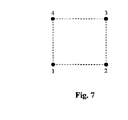
- Fig. 7 is a schematic diagram of a 4-element rectangle array
- Fig. 8 is a schematic diagram of a 4-element T-form array.
- a key point of the invention is to build a single-azimuth echo signal model received by a non-linear antenna array, to transfer a channel calibration problem to a parameter estimation problem, and to obtain comparatively accurate channel mismatch estimation.
- An ocean echo can be regard as a plane wave.
- 2 / ⁇ i 1 L
- Y i l g i ⁇ e j ⁇ ⁇ i [ A l ⁇ e j ⁇ 2 ⁇ ⁇ ⁇ ⁇ x i ⁇ sin ⁇ i + y i ⁇ cos ⁇ i + W i ( l ) ]
- Y i [ Y i 1 , Y i 2 , ⁇ , Y i L ⁇ ]
- Equation (5) cannot actually be used for estimating channel phase mismatchs, and should be improved.
- Theoretic analyses and simulation experiments indicate that the above-mentioned channel phase calibration method is only applicable to non-linear arrays and at least two single-azimuth echoes, which have angle differences other than 0°or 180°, must be available.
- the channel phase mismatch estimation is actually a multidimensional parameter estimation problem and may be obtained via multidimensional searching since it relates to all array elements and therefore the selection of optimization methods. Due to the existence of local minimum, global optimization methods (Referring to the paper " From Local Minimum to Global optimization" by Tang F and Wang L, Computer Engineering and Applications, 2002.6: 56 ⁇ 58 ) must be used to estimate the channel phase mismatches. However, the methods cannot meet a real-time requirement for a very heavy computing load as there are too many parameters (more than 100). The invention employs special processing to reduce the computing load, which is explained in detail below.
- Fig. 5 illustrates a simplest non-linear array, which is a triangular array constituted by three array elements not lying on the same straight line. If the channel phase mismatch coefficients of the triangular array and the arrival angles of single-azimuth echoes are estimated by three single-azimuth echoes only, a 5-dimension searching can be judged from equation (6) (a certain array element as the reference channel). Since few dimensions are involved, even the global optimization methods such as simulated annealing, evolution computing, chaos searching and random sampling are used, the computing load of the 5-dimension searching is not heavy, and therefore the real-time requirement can be met.
- a certain triangular array included therein can be used to implement pre-estimation of initial values of the parameters to be estimated, and then local optimization methods (e.g., steepest descent method) can be used to obtain more precise estimates, so as to reduce the computing load of multi-dimension parameter estimation.
- local optimization methods e.g., steepest descent method
- the result of local optimization is also the global optimum, while the computing load of local optimization is much smaller than that of global optimization.
- the above pre-estimation of initial values takes up most of the calculating time, but it relates to the global optimization of 5-dimension searching at most, and therefore can meet the real-time requirement.
- Fig. 6 is an M-element L-form array of an embodiment of the invention.
- Array element 1 ⁇ M -1 form a uniform linear array, from which more than one combination of translation invariant dual array-element couples for detecting single-azimuth echoes can be divided.
- Channel amplitude calibration can be realized by equation (3), and channel phase calibration is the key point.
- a triangular array constituted by the array element 1, 2 and M is used for estimating initial values of parameters, and the channel phase calibration can be implemented by equation (6) and the special processing.
- Fig. 7 is a 4-element rectangular array.
- 4 array elements constitute only one combination of translation invariant dual array-element couples for detecting single-azimuth echoes, and a triangular array constituted by any three array elements can be used for estimating initial values of parameters.
- Fig. 8 is a 4-element T-form array.
- the array element 1 ⁇ 3 constitute a 3-element uniform linear array, from which only one combination of translation invariant dual array-element couples for detecting single-azimuth echoes can be divided.
- Both the two triangular arrays constituted by the array element 1, 2, 4 and array element 2, 3, 4 can be used for estimating initial values of parameters.
- the channel calibration method described in the invention has gained success in high frequency surface wave radars, however, in essence, the method is possible to be applied to other detection systems or communication systems receiving a large number of single-azimuth signals.
Landscapes
- Engineering & Computer Science (AREA)
- Radar, Positioning & Navigation (AREA)
- Remote Sensing (AREA)
- Computer Networks & Wireless Communication (AREA)
- Physics & Mathematics (AREA)
- General Physics & Mathematics (AREA)
- Radar Systems Or Details Thereof (AREA)
Applications Claiming Priority (2)
| Application Number | Priority Date | Filing Date | Title |
|---|---|---|---|
| CN2005100184383A CN1664611A (zh) | 2005-03-24 | 2005-03-24 | 一种基于非直线天线阵列的无源通道校正方法 |
| PCT/CN2006/000453 WO2006099800A1 (fr) | 2005-03-24 | 2006-03-21 | Procede de reglage de canal passif base sur un reseau d’antennes |
Publications (2)
| Publication Number | Publication Date |
|---|---|
| EP1879043A1 true EP1879043A1 (fr) | 2008-01-16 |
| EP1879043A4 EP1879043A4 (fr) | 2013-01-30 |
Family
ID=35035795
Family Applications (1)
| Application Number | Title | Priority Date | Filing Date |
|---|---|---|---|
| EP06722105A Withdrawn EP1879043A4 (fr) | 2005-03-24 | 2006-03-21 | Procede de reglage de canal passif base sur un reseau d antennes |
Country Status (5)
| Country | Link |
|---|---|
| US (1) | US7667639B2 (fr) |
| EP (1) | EP1879043A4 (fr) |
| CN (1) | CN1664611A (fr) |
| AU (1) | AU2006227098B2 (fr) |
| WO (1) | WO2006099800A1 (fr) |
Cited By (3)
| Publication number | Priority date | Publication date | Assignee | Title |
|---|---|---|---|---|
| WO2016040693A1 (fr) * | 2014-09-11 | 2016-03-17 | Cpg Technologies, Llc | Détection de subsurface en utilisant des modes d'ondes de surface guidées sur des milieux à perte |
| CN105554780A (zh) * | 2015-12-23 | 2016-05-04 | 哈尔滨工业大学 | 毫米波下Massive MIMO多小区协作波束分配方法 |
| US10101444B2 (en) | 2014-09-11 | 2018-10-16 | Cpg Technologies, Llc | Remote surface sensing using guided surface wave modes on lossy media |
Families Citing this family (36)
| Publication number | Priority date | Publication date | Assignee | Title |
|---|---|---|---|---|
| CN1804656B (zh) * | 2006-01-20 | 2010-04-14 | 武汉大学 | 一种利用电离层回波进行高频雷达天线阵列通道校正的方法 |
| CN101923157B (zh) * | 2010-07-29 | 2013-05-01 | 西安空间无线电技术研究所 | 一种星载双通道角跟踪校准系统 |
| DE102012004308B4 (de) * | 2012-03-01 | 2018-09-20 | Atlas Elektronik Gmbh | Annäherungssensor und Verfahren zum Bestimmen der Annäherung an einen elektrisch leitfähigen Körper |
| CN104854473B (zh) * | 2012-11-05 | 2017-05-24 | 泰克年研究发展基金会公司 | 使用多普勒聚焦的亚奈奎斯特雷达处理 |
| JP5788860B2 (ja) * | 2012-12-28 | 2015-10-07 | 日本電信電話株式会社 | 無線通信システムおよび無線通信方法 |
| RU2540982C1 (ru) * | 2013-09-10 | 2015-02-10 | ОТКРЫТОЕ АКЦИОНЕРНОЕ ОБЩЕСТВО "НИИ измерительных приборов-Новосибирский завод имени Коминтерна" /ОАО "НПО НИИИП-НЗиК"/ | Способ определения координат целей (варианты) и комплекс для его реализации (варианты) |
| CN104698444B (zh) * | 2013-12-23 | 2017-04-26 | 中国科学院电子学研究所 | 确定阵元位置误差对阵列天线三维成像质量影响的方法 |
| RU2567114C1 (ru) * | 2014-05-05 | 2015-11-10 | Открытое акционерное общество "Азовский оптико-механический завод" (ОАО "АОМЗ") | Система для измерения координат объекта навигации |
| CN104267386B (zh) * | 2014-10-17 | 2016-09-14 | 武汉大学 | 一种外辐射源雷达旋转阵列的无源通道校正方法及系统 |
| CN104378170B (zh) * | 2014-10-27 | 2017-02-08 | 西安电子科技大学 | 一种临近空间动态等离子鞘套信道建模及模拟的方法 |
| US20170307755A1 (en) | 2016-04-20 | 2017-10-26 | YoR Labs | Method and System for Determining Signal Direction |
| DE102017204496A1 (de) * | 2017-03-17 | 2018-09-20 | Robert Bosch Gmbh | Verfahren und Radarvorrichtung zum Ermitteln von radialer relativer Beschleunigung mindestens eines Zieles |
| CN107783086B (zh) * | 2017-10-17 | 2021-01-05 | 中国电子科技集团公司第三十八研究所 | 用于诊断天线阵口径幅相场的畸变位置的方法 |
| CN109856627A (zh) * | 2019-01-11 | 2019-06-07 | 中国船舶重工集团公司第七二四研究所 | 基于空间补零插值的三角阵相控阵2d-fft测向方法 |
| CN110007267B (zh) * | 2019-01-29 | 2020-08-18 | 杭州电子科技大学 | 一种基于混合基线的均匀圆阵干涉仪测向解模糊方法 |
| CN110286370B (zh) * | 2019-05-08 | 2022-03-22 | 自然资源部第一海洋研究所 | 航行状态下的船载地波雷达运动补偿方法 |
| US11998391B1 (en) | 2020-04-02 | 2024-06-04 | yoR Labs, Inc. | Method and apparatus for composition of ultrasound images with integration of “thick-slice” 3-dimensional ultrasound imaging zone(s) and 2-dimensional ultrasound zone(s) utilizing a multi-zone, multi-frequency ultrasound image reconstruction scheme with sub-zone blending |
| US11547386B1 (en) | 2020-04-02 | 2023-01-10 | yoR Labs, Inc. | Method and apparatus for multi-zone, multi-frequency ultrasound image reconstruction with sub-zone blending |
| CN111505391B (zh) * | 2020-05-09 | 2022-05-31 | 北京航空航天大学云南创新研究院 | 一种检测阵列天线中的失配天线单元的方法 |
| CN114065894B (zh) * | 2020-07-31 | 2025-09-23 | 中移(苏州)软件技术有限公司 | 一种网络编排方法、装置、设备和存储介质 |
| US11832991B2 (en) | 2020-08-25 | 2023-12-05 | yoR Labs, Inc. | Automatic ultrasound feature detection |
| US12138123B2 (en) | 2020-08-25 | 2024-11-12 | yoR Labs, Inc. | Unified interface for visualizing 2D, 3D and 4D ultrasound images |
| US11344281B2 (en) | 2020-08-25 | 2022-05-31 | yoR Labs, Inc. | Ultrasound visual protocols |
| JP7257369B2 (ja) * | 2020-09-28 | 2023-04-13 | 京セラ株式会社 | 電子機器、電子機器の制御方法、及びプログラム |
| US12618955B1 (en) | 2020-11-05 | 2026-05-05 | yoR Labs, Inc. | Adaptive retrospective transmit beamforming (RTB) for a lowpower handheld ultrasound scanner |
| US11751850B2 (en) | 2020-11-19 | 2023-09-12 | yoR Labs, Inc. | Ultrasound unified contrast and time gain compensation control |
| US11704142B2 (en) | 2020-11-19 | 2023-07-18 | yoR Labs, Inc. | Computer application with built in training capability |
| CN112986935B (zh) * | 2021-02-24 | 2022-12-20 | 湖北中南鹏力海洋探测系统工程有限公司 | 一种基于地貌共形布阵的多元阵列通道无源校准方法 |
| US12539170B2 (en) | 2021-08-17 | 2026-02-03 | yoR Labs, Inc. | Orthogonally oriented steering controls for ICE catheter |
| WO2023033835A1 (fr) * | 2021-09-03 | 2023-03-09 | Zeku, Inc. | Appareil et procédé d'estimation de paramètres de faisceau pour détermination de ligne de visée |
| CN115130362B (zh) * | 2022-07-08 | 2023-04-07 | 中国科学院声学研究所 | 一种基于信道匹配的阵列阵元位置校准方法及系统 |
| CN115932760B (zh) * | 2022-11-24 | 2026-03-27 | 森思泰克河北科技有限公司 | 异形线阵雷达的校准方法、装置、雷达及存储介质 |
| US12542212B2 (en) | 2023-02-02 | 2026-02-03 | yoR Labs, Inc. | Ice ultrasound remote control |
| US12156761B1 (en) | 2024-03-05 | 2024-12-03 | yoR Labs, Inc. | Bayesian anatomically-driven, artificial-intelligence based intracardiac echocardiography object detection and prediction |
| USD1118921S1 (en) | 2024-09-11 | 2026-03-17 | yoR Labs, Inc. | Catheter handle |
| USD1115033S1 (en) | 2024-09-11 | 2026-02-24 | yoR Labs, Inc. | Intracardiac echocardiography box |
Family Cites Families (4)
| Publication number | Priority date | Publication date | Assignee | Title |
|---|---|---|---|---|
| US5361072A (en) * | 1992-02-28 | 1994-11-01 | Codar Ocean Sensors, Ltd. | Gated FMCW DF radar and signal processing for range/doppler/angle determination |
| FR2762397B1 (fr) * | 1997-04-18 | 1999-07-09 | Thomson Csf | Dispositif d'auto test de la chaine d'emission et de reception d'un radar, notamment pour automobile |
| CN1321331C (zh) * | 2003-06-30 | 2007-06-13 | 武汉大学 | 一种利用海洋回波进行阵列通道校正的方法 |
| CN1328594C (zh) * | 2004-05-17 | 2007-07-25 | 中国人民解放军空军雷达学院 | 用高精度辅助阵元进行阵列校正与信源测向的方法 |
-
2005
- 2005-03-24 CN CN2005100184383A patent/CN1664611A/zh active Pending
-
2006
- 2006-03-21 AU AU2006227098A patent/AU2006227098B2/en not_active Ceased
- 2006-03-21 EP EP06722105A patent/EP1879043A4/fr not_active Withdrawn
- 2006-03-21 WO PCT/CN2006/000453 patent/WO2006099800A1/fr not_active Ceased
-
2007
- 2007-09-22 US US11/859,746 patent/US7667639B2/en not_active Expired - Fee Related
Cited By (5)
| Publication number | Priority date | Publication date | Assignee | Title |
|---|---|---|---|---|
| WO2016040693A1 (fr) * | 2014-09-11 | 2016-03-17 | Cpg Technologies, Llc | Détection de subsurface en utilisant des modes d'ondes de surface guidées sur des milieux à perte |
| US10101444B2 (en) | 2014-09-11 | 2018-10-16 | Cpg Technologies, Llc | Remote surface sensing using guided surface wave modes on lossy media |
| US10175203B2 (en) | 2014-09-11 | 2019-01-08 | Cpg Technologies, Llc | Subsurface sensing using guided surface wave modes on lossy media |
| CN105554780A (zh) * | 2015-12-23 | 2016-05-04 | 哈尔滨工业大学 | 毫米波下Massive MIMO多小区协作波束分配方法 |
| CN105554780B (zh) * | 2015-12-23 | 2019-03-12 | 哈尔滨工业大学 | 毫米波下Massive MIMO多小区协作波束分配方法 |
Also Published As
| Publication number | Publication date |
|---|---|
| US20080012753A1 (en) | 2008-01-17 |
| AU2006227098A1 (en) | 2006-09-28 |
| AU2006227098B2 (en) | 2010-07-29 |
| WO2006099800A1 (fr) | 2006-09-28 |
| US7667639B2 (en) | 2010-02-23 |
| EP1879043A4 (fr) | 2013-01-30 |
| CN1664611A (zh) | 2005-09-07 |
Similar Documents
| Publication | Publication Date | Title |
|---|---|---|
| US7667639B2 (en) | Passive channel calibration method based on non-linear antenna array | |
| Billingsley et al. | Statistical analyses of measured radar ground clutter data | |
| Melvin et al. | An approach to knowledge-aided covariance estimation | |
| Cuomo et al. | Ultrawide-band coherent processing | |
| Melvin | Space-time adaptive radar performance in heterogeneous clutter | |
| US5945940A (en) | Coherent ultra-wideband processing of sparse multi-sensor/multi-spectral radar measurements | |
| US7038618B2 (en) | Method and apparatus for performing bistatic radar functions | |
| CN107976660A (zh) | 弹载多通道雷达超低空目标分析与多径回波建模方法 | |
| El-Absi et al. | Chipless RFID infrastructure based self-localization: Testbed evaluation | |
| McDonald et al. | Coherent radar processing in sea clutter environments, part 1: modelling and partially adaptive STAP performance | |
| Sebt et al. | Geometric arithmetic mean method for low altitude target elevation angle tracking | |
| KR101934035B1 (ko) | 해류 정보 측정 방법과 프로그램 및 이를 이용한 해양 레이더 시스템 | |
| Lombardo et al. | Multiband coherent radar detection against compound-Gaussian clutter | |
| Huang et al. | Array‐based target localisation in ATSC DTV passive radar | |
| CN1321331C (zh) | 一种利用海洋回波进行阵列通道校正的方法 | |
| CN100585429C (zh) | 一种基于非直线天线阵列的无源通道校正方法 | |
| CN115421123B (zh) | 岸基超高频雷达风向反演方法及系统 | |
| Zhu et al. | Robust moving targets detection and velocity estimation using multi-channel and multi-look SAR images | |
| AU2016373312B2 (en) | Method for spectral estimation of the clutter of a haline liquid medium | |
| Wijesundara et al. | Comparison of maximum-likelihood estimation and other methods for clutter Doppler centroid estimation | |
| Rahayu et al. | Sequential-compressive-range azimuth estimation in radar signal processing | |
| Coutts | Passive localization of moving emitters using out-of-plane multipath | |
| Islam et al. | Multiple Target Detection by URA-based Surveillance Radar | |
| Pettersson et al. | Performance of moving target parameter estimation using SAR | |
| Zhou et al. | A Doppler Estimation Algorithm for Radar Imaging Based on Low-Rank Embedding Theory |
Legal Events
| Date | Code | Title | Description |
|---|---|---|---|
| PUAI | Public reference made under article 153(3) epc to a published international application that has entered the european phase |
Free format text: ORIGINAL CODE: 0009012 |
|
| 17P | Request for examination filed |
Effective date: 20071024 |
|
| AK | Designated contracting states |
Kind code of ref document: A1 Designated state(s): AT BE BG CH CY CZ DE DK EE ES FI FR GB GR HU IE IS IT LI LT LU LV MC NL PL PT RO SE SI SK TR |
|
| DAX | Request for extension of the european patent (deleted) | ||
| A4 | Supplementary search report drawn up and despatched |
Effective date: 20130107 |
|
| RIC1 | Information provided on ipc code assigned before grant |
Ipc: G01S 13/536 20060101ALI20121221BHEP Ipc: G01S 7/40 20060101AFI20121221BHEP Ipc: G01S 13/06 20060101ALI20121221BHEP Ipc: G01S 13/34 20060101ALI20121221BHEP |
|
| GRAP | Despatch of communication of intention to grant a patent |
Free format text: ORIGINAL CODE: EPIDOSNIGR1 |
|
| INTG | Intention to grant announced |
Effective date: 20180504 |
|
| STAA | Information on the status of an ep patent application or granted ep patent |
Free format text: STATUS: THE APPLICATION IS DEEMED TO BE WITHDRAWN |
|
| 18D | Application deemed to be withdrawn |
Effective date: 20180915 |