EP1879087A2 - Dispositif de détection de position pour un élément fonctionnel déplaçable et motorisé dans un véhicule - Google Patents
Dispositif de détection de position pour un élément fonctionnel déplaçable et motorisé dans un véhicule Download PDFInfo
- Publication number
- EP1879087A2 EP1879087A2 EP07013244A EP07013244A EP1879087A2 EP 1879087 A2 EP1879087 A2 EP 1879087A2 EP 07013244 A EP07013244 A EP 07013244A EP 07013244 A EP07013244 A EP 07013244A EP 1879087 A2 EP1879087 A2 EP 1879087A2
- Authority
- EP
- European Patent Office
- Prior art keywords
- functional element
- drive
- rotary
- encoder
- rotary encoder
- Prior art date
- Legal status (The legal status is an assumption and is not a legal conclusion. Google has not performed a legal analysis and makes no representation as to the accuracy of the status listed.)
- Withdrawn
Links
Images


Classifications
-
- G—PHYSICS
- G05—CONTROLLING; REGULATING
- G05B—CONTROL OR REGULATING SYSTEMS IN GENERAL; FUNCTIONAL ELEMENTS OF SUCH SYSTEMS; MONITORING OR TESTING ARRANGEMENTS FOR SUCH SYSTEMS OR ELEMENTS
- G05B19/00—Program-control systems
- G05B19/02—Program-control systems electric
- G05B19/18—Numerical control [NC], i.e. automatically operating machines, in particular machine tools, e.g. in a manufacturing environment, so as to execute positioning, movement or co-ordinated operations by means of program data in numerical form
- G05B19/19—Numerical control [NC], i.e. automatically operating machines, in particular machine tools, e.g. in a manufacturing environment, so as to execute positioning, movement or co-ordinated operations by means of program data in numerical form characterised by positioning or contouring control systems, e.g. to control position from one programmed point to another or to control movement along a programmed continuous path
- G05B19/21—Numerical control [NC], i.e. automatically operating machines, in particular machine tools, e.g. in a manufacturing environment, so as to execute positioning, movement or co-ordinated operations by means of program data in numerical form characterised by positioning or contouring control systems, e.g. to control position from one programmed point to another or to control movement along a programmed continuous path using an incremental digital measuring device
- G05B19/23—Numerical control [NC], i.e. automatically operating machines, in particular machine tools, e.g. in a manufacturing environment, so as to execute positioning, movement or co-ordinated operations by means of program data in numerical form characterised by positioning or contouring control systems, e.g. to control position from one programmed point to another or to control movement along a programmed continuous path using an incremental digital measuring device for point-to-point control
-
- B—PERFORMING OPERATIONS; TRANSPORTING
- B60—VEHICLES IN GENERAL
- B60N—SEATS SPECIALLY ADAPTED FOR VEHICLES; VEHICLE PASSENGER ACCOMMODATION NOT OTHERWISE PROVIDED FOR
- B60N2/00—Seats specially adapted for vehicles; Arrangement or mounting of seats in vehicles
- B60N2/02—Seats specially adapted for vehicles; Arrangement or mounting of seats in vehicles the seat or part thereof being movable, e.g. adjustable
- B60N2/0224—Non-manual adjustments, e.g. with electrical operation
- B60N2/0244—Non-manual adjustments, e.g. with electrical operation with logic circuits
- B60N2/0272—Non-manual adjustments, e.g. with electrical operation with logic circuits using sensors or detectors for detecting the position of seat parts
-
- B—PERFORMING OPERATIONS; TRANSPORTING
- B60—VEHICLES IN GENERAL
- B60N—SEATS SPECIALLY ADAPTED FOR VEHICLES; VEHICLE PASSENGER ACCOMMODATION NOT OTHERWISE PROVIDED FOR
- B60N2/00—Seats specially adapted for vehicles; Arrangement or mounting of seats in vehicles
- B60N2/02—Seats specially adapted for vehicles; Arrangement or mounting of seats in vehicles the seat or part thereof being movable, e.g. adjustable
- B60N2/04—Seats specially adapted for vehicles; Arrangement or mounting of seats in vehicles the seat or part thereof being movable, e.g. adjustable the whole seat being movable
- B60N2/06—Seats specially adapted for vehicles; Arrangement or mounting of seats in vehicles the seat or part thereof being movable, e.g. adjustable the whole seat being movable slidable
- B60N2/067—Seats specially adapted for vehicles; Arrangement or mounting of seats in vehicles the seat or part thereof being movable, e.g. adjustable the whole seat being movable slidable by linear actuators, e.g. linear screw mechanisms
-
- G—PHYSICS
- G01—MEASURING; TESTING
- G01D—MEASURING NOT SPECIALLY ADAPTED FOR A SPECIFIC VARIABLE; ARRANGEMENTS FOR MEASURING TWO OR MORE VARIABLES NOT COVERED IN A SINGLE OTHER SUBCLASS; TARIFF METERING APPARATUS; MEASURING OR TESTING NOT OTHERWISE PROVIDED FOR
- G01D5/00—Mechanical means for transferring the output of a sensing member; Means for converting the output of a sensing member to another variable where the form or nature of the sensing member does not constrain the means for converting; Transducers not specially adapted for a specific variable
- G01D5/12—Mechanical means for transferring the output of a sensing member; Means for converting the output of a sensing member to another variable where the form or nature of the sensing member does not constrain the means for converting; Transducers not specially adapted for a specific variable using electric or magnetic means
- G01D5/244—Mechanical means for transferring the output of a sensing member; Means for converting the output of a sensing member to another variable where the form or nature of the sensing member does not constrain the means for converting; Transducers not specially adapted for a specific variable using electric or magnetic means influencing characteristics of pulses or pulse trains; generating pulses or pulse trains
- G01D5/245—Mechanical means for transferring the output of a sensing member; Means for converting the output of a sensing member to another variable where the form or nature of the sensing member does not constrain the means for converting; Transducers not specially adapted for a specific variable using electric or magnetic means influencing characteristics of pulses or pulse trains; generating pulses or pulse trains using a variable number of pulses in a train
- G01D5/2451—Incremental encoders
- G01D5/2452—Incremental encoders incorporating two or more tracks having an (n, n+1, ...) relationship
-
- G—PHYSICS
- G01—MEASURING; TESTING
- G01D—MEASURING NOT SPECIALLY ADAPTED FOR A SPECIFIC VARIABLE; ARRANGEMENTS FOR MEASURING TWO OR MORE VARIABLES NOT COVERED IN A SINGLE OTHER SUBCLASS; TARIFF METERING APPARATUS; MEASURING OR TESTING NOT OTHERWISE PROVIDED FOR
- G01D2205/00—Indexing scheme relating to details of means for transferring or converting the output of a sensing member
- G01D2205/20—Detecting rotary movement
- G01D2205/28—The target being driven in rotation by additional gears
Definitions
- the present invention relates to a position detection arrangement for a motor-adjustable functional element in a motor vehicle with the features of the preamble of claim 1. Furthermore, the invention relates to a drive unit in a motor vehicle having the features of the preamble of claim 18 and a functional unit in a motor vehicle having the features of The preamble of claim 19.
- adjustable functional element is to be understood here comprehensively.
- this generally includes control elements in a motor vehicle and closure elements such as a tailgate, a boot lid, an engine compartment flap, a luggage compartment flap, a side door - also sliding door - and a lifting roof of a motor vehicle.
- closure elements such as a tailgate, a boot lid, an engine compartment flap, a luggage compartment flap, a side door - also sliding door - and a lifting roof of a motor vehicle.
- motorized adjustable windows, mirrors or vehicle seats are included.
- a drive arrangement is provided, which is coupled via a drive train with the respective functional element.
- a known drive arrangement for a tailgate ( DE 20 2005 000 559 U1 ) has two spindle drives, which are coupled on the one hand with the body of the motor vehicle and on the other hand with the tailgate.
- the two spindle drives are arranged on the opposite sides of the tailgate.
- Another known drive arrangement for a tailgate ( DE 20 2004 016 543 U1 ) is equipped with a push rod drive, wherein the push rod is articulated to a coupled to the tailgate lever.
- a control device which sends suitable control signals to the drive arrangement based on the absolute position of the functional element.
- absolute position is meant an indication that provides information about the actual position of the functional element without further calculation. In the case of a tailgate, this is, for example, an angle which is related to the non-adjustable part of the body.
- control or regulation of the motor adjustment can only be as good as the present in the control device position data on the current absolute position of the functional element.
- the determination of this position data is the position detection arrangement in question.
- the known position detection arrangement ( DE 101 45 711 B4 ), from which the invention proceeds, is equipped with two incremental encoders.
- a rotary encoder serves to detect the position of the adjustable functional element. This detection is done by counting the pulses generated by the incremental encoder.
- the second rotary encoder generates pulses that are out of phase with the pulses of the first rotary encoder.
- the encoder signals of the second rotary encoder are used exclusively for determining the current adjustment direction of the functional element.
- angle encoder encoders for the detection of the absolute position of the functional element also designed as an angle encoder encoders are used. Depending on the angular position, such angle encoders produce encoded encoder signals which already provide information about the absolute position.
- Such angle encoders are known as single-turn angle encoders and multi-turn angle encoders. In a single-turn angle encoder, the encoder signals are repeated periodically after one complete revolution. In a multi-turn angle encoder, the encoding of the absolute position over several rotations is provided.
- angle encoders are also known from the field of tailgates and bootlids of motor vehicles ( DE 199 44 554 A1 ).
- a disadvantage of angle encoders are always the high cost.
- An example of this shows the DE 33 42 940 C2 .
- the invention is based on the problem of designing and further developing the known position detection arrangement such that the detection of the absolute position of the functional element can be implemented with high accuracy, high operational reliability even in an emergency and at low cost.
- the offset can be realized simply by the fact that the two incremental encoders different drive components are assigned to the drive train, which rotate at different speeds during the adjustment of the functional element.
- the two encoders are assigned to selected drive components of the drive train, which are already present anyway.
- On an additional transmission as provided for example in conventional multi-turn angle encoders, can basically be dispensed with.
- the two rotary encoders with constant adjustment of the functional element each generate encoder signals with different pulse frequencies.
- a preferred variant of the determination of the absolute position of the functional element is the subject of claim 6.
- the time difference between a pulse of a rotary encoder and the subsequent pulse of the other rotary encoder is a measure of the absolute position of the functional element.
- phase difference between the current pulse of a rotary encoder and the current pulse of the other rotary encoder is a measure of the absolute position of the functional element.
- Claim 9 contains preferred possibilities for the design of the rotary encoder. Particularly cost-effective and robust at the same time is the design as a Hall sensor.
- the preferred embodiment according to claim 12 is particularly advantageous in the detection of the absolute position of a tailgate o.
- a motor vehicle The necessary different rotational speeds can be realized here in a simple manner by a different control of the two spindle drives.
- a motor vehicle is the preferred embodiment according to claims 13, 14.
- the offset between the encoder signals of the two encoders is here realized preferably by coordinated designs of the rotary gear.
- a drive unit for an adjustable functional element with the described drive arrangement for the motorized adjustment of the functional element and the described position detection arrangement for detecting the position of the functional element as such is claimed.
- a functional unit in a motor vehicle with the described functional element, the described drive arrangement and the described position detection arrangement for detecting the position of the functional element as such is claimed. Again, reference may be made to the above statements.
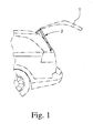
- the proposed position detection arrangement can be applied to all possible functional elements 1, in particular closure elements, in a motor vehicle. Reference is made to the list in the introduction, with the application on tailgates and side doors in the foreground. The drawing relates to the application of the position detection arrangement for a designed as a tailgate functional element 1. This is not to be understood as limiting.
- a spindle-based drive arrangement 2 for motorized adjustment of the tailgate 1 is provided.
- Fig. 3 shows a push rod based drive assembly 2 for a tailgate 1.
- the respective drive assembly 2 is coupled via a drive train 3 with the tailgate 1 and the tailgate 1 is characterized by a motor adjustable.
- the drive train 3 is regularly part of the drive assembly. 2
- the position detection arrangement is equipped with two incremental encoders 4, 5, which are assigned to the drive train 3.
- Incremental encoders are characterized in that they produce over a full revolution substantially identical pulse-like encoder signals that repeat periodically with each revolution. It may also be that only a single pulse is generated per revolution.
- control device 6 which is coupled to the rotary outputs 4, 5 and u.a. the evaluation of the encoder signals generated by the encoders 4, 5 is used.
- the arrangement is such that when adjusting the functional element 1, an offset between the encoder signals of the two rotary encoder 4, 5 is formed.
- a first drive component 7 of the drive train 3 and the second encoder 5 a second drive component 8 of the drive train 3 is assigned, these two drive components 7, 8 in the adjustment of the functional element 1 different turn quickly (Fig. 2, 3). With the different rotational speeds of the two drive components 7, 8 can be achieved during the adjustment of the functional element 1 progressive offset between the two pulse-like encoder signals.
- control device 6 is designed so that it determines the current absolute position of the functional element 1 thereof.
- This design of the control device 6 includes both their hardware and their software.
- the arrangement is such that the offset over the entire displacement of the functional element 1 is not greater than a period of the encoder signal with a higher pulse frequency, since only so a clear assignment of the offset to the position of the functional element 1 is possible. Otherwise, it must be ensured that any exceeding of this maximum offset quantity is stored and taken into account in the determination of the absolute position. This consideration starts again from the situation of the constant adjustment of the functional element 1.
- the arrangement is such that the two rotary encoders 4, 5 in the adjustment of the functional element 1 generate encoder signals with at least qualitatively identical pulse shape.
- the individual pulses seen on the time axis may be stretched or compressed, apart from this compression or extension but are identical in terms of their shape.
- all pulses are substantially sinusoidal, parabolic, sawtooth o. The like ..
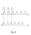
- the control device 6 determines the absolute position of the functional element 1 from the time difference between a pulse of one rotary encoder 4 and the subsequent pulse of the other rotary encoder 5. For example, the distance of the pulse peaks of the two encoder signals is determined here. This is exemplified in Fig. 4.
- the progressive offset between the rotary encoder signals (“D4": rotary encoder 4, "D5": rotary encoder 5) is represented there by the time differences ⁇ t 1 , ⁇ t 2 and ⁇ t 3 .
- FIG. 4 The illustration in FIG. 4 is based on the situation of the constant adjustment of the functional element 1.
- the pulse shapes are chosen only as an example.
- the adjustment speed can be easily obtained from the previously determined values. It is not important to determine the actual adjustment speed. It is only necessary to determine a value that represents a measure of the current adjustment speed. Such a measure can be determined, for example, from the frequency and / or the wavelength of one of the encoder signals. An engine speed can also be used as a measure of the adjustment speed. Ultimately, the speed or rotational speed of all components can be used, which are motion-coupled with the functional element 1.
- the second preferred way to detect the offset is that the controller 6 determines the absolute position of the functional element 1 from the phase difference between the current pulse of a rotary encoder 4 and the current pulse of the other rotary encoder 5.
- This variant can be used if the pulses have a shape which can be resolved without difficulty, for example a sinusoidal shape, a parabolic shape or a sawtooth shape or the like. Then can be determined from the phase difference according to the offset between the two encoder signals.
- the determination of the absolute position of the functional element 1 from the phase difference between the current pulse of one rotary encoder 4 and the current pulse of the other rotary encoder 5 is particularly advantageous when seen on the adjustment of the functional element 1, the two encoders 4, 5 each at any time Give encoder signal that provides information about the phase and thus about the phase difference.
- these encoder signals consist of preferably sinusoidal, parabolic or sawtooth-shaped pulses which adjoin one another directly.
- the phase difference is continuously, and not only in certain trigger times or the like., Determined.
- the determination of the absolute position of the functional element 1 from the phase difference between the current pulse of a rotary encoder 4 and the current pulse of Other rotary encoder 5 is particularly advantageous because the determination of the absolute position is possible without having to adjust the functional element 1. An above-mentioned determination of a time difference is not required.
- the two rotary encoders 4, 5 are configured identically and are assigned only to different drive components 7, 8. In a preferred embodiment, however, it is such that the rotary encoder 4, 5 are each configured differently. This means that they produce different encoder signals assuming identical revolution. For example, it may be provided that the rotary encoder 4, 5 per revolution of the corresponding drive component 7, 8 generate encoder signals with a different number of pulses. This makes it easy to set an optimal ratio of the pulse frequencies of the two encoder signals.
- the rotary encoder 4, 5 could be designed as magnetic, as inductive or optical sensors.
- the rotary encoder 4, 5 configured as Hall sensors that are inexpensive and at the same time robust. Then, the drive components 7, 8, to which the rotary encoders 4, 5 are assigned, are provided with a certain number of magnets, which pass by the Hall sensor when the drive components 7, 8 rotate. By increasing the number of magnets, the measurement accuracy can be increased in a simple manner.
- the rotary encoders 4, 5 can also be advantageous to configure the rotary encoders 4, 5 as MR angle sensors or as AMR angle sensors, which are then used in the sense of incremental encoders. This can be achieved overall high accuracy.
- the drive assembly 2 has a drive 9 with a motor unit 10 and a downstream transmission 11, wherein the drive 9 acts on the functional element 1 via the drive train 3. It will be explained that more than one drive 9 can be provided.
- the transmission 11 is designed as a multi-stage transmission 11 (while initially only the lower in Fig. 3 area of the drive assembly 2 is taken into account).
- the spur gears 12, 13 and 14 Part of the transmission 11 in the embodiment shown in FIG. 3 in any case, the spur gears 12, 13 and 14.
- the rotary encoder 4, 5 are designed as Hall sensors. Accordingly, the spur gears 13, 14 are equipped at their periphery with corresponding magnets. The two spur gears 13, 14 are due to their different diameter different speed rotating drive components 7, 8 in the above sense.
- the push rod 16a is in the assembled state in terms of drive technology coupled to the tailgate 1 (shown very schematically in FIG. 1).
- a second push rod arrangement 15b, 16b is connected to the motor unit 10 via a cable or belt drive 17.
- the second push rod 16b is coupled in the assembled state drive technology with the tailgate 1.
- the gear 11 on the one hand and the rope or belt drive 17 on the other hand are designed so that the push rods 16a, 16b always run synchronously.
- the drive arrangement 2 has two drives 9a, 9b, which act on the functional element 1 via two partial drive trains 3a, 3b.
- the motor unit 10 of the one drive 9a is the motor unit 10 of the other drive 9b.
- the two drives 9a, 9b thus share the one motor unit 10.
- each drive 9a, 9b has its own, only schematically illustrated motor unit 10 with a downstream transmission 11.
- the two drives 9a, 9b act on the tailgate 1 via two partial drive trains 3a, 3b. It is essential that one rotary encoder 4 is assigned to a drive component 7 of one partial drive train 3a and the other rotary encoder 5 is assigned to a drive component 8 of the other partial drive train 3b these two drive components 7, 8 rotate at different speeds during the adjustment of the functional element 1. How this is realized will be explained.
- the two drives 9a, 9b designed as spindle drives with a spindle-spindle nut gear.
- one rotary encoder 4 is assigned to one spindle drive 9a and the other rotary encoder 5 to the other spindle drive 9b.
- the one encoder 4 of the spindle 18a of a spindle drive 9a and the other encoder 5 of the spindle 18b of the other spindle drive 9b is assigned.
- the two spindles 18a, 18b thus correspond to the drive components 7, 8 in the above sense.
- Different rotational speeds for the spindles 18a, 18b can be easily achieved by a corresponding control of the motor units of the spindle drives 9a, 9b.
- the spindles 18a, 18b of the two spindle drives 9a, 9b have different spindle pitches. It is preferably such that the spindle pitch of the spindle 18a of a spindle drive 9a is about 5% larger than the spindle pitch of the spindle 18b of the other spindle drive 9b.
- the respective arrangement of the rotary encoder 4, 5 can be seen in Fig. 2 the partial representations.
- the spindles 18a, 18b are here each equipped with a measuring disk 19a, 19b, each equipped with a certain number of magnets for the preferably designed as Hall sensors rotary encoder 4, 5.
- the one rotary encoder 4 of the motor unit or an intermediate gear section and the second rotary encoder 5 of the spindle 18 a is assigned. Then both rotary encoders 4, 5 are arranged within a partial drive train 3a.
- the rotary encoders 4, 5 are always assigned elements 4b, 5b, 7, 8, 19a, 19b, which are set in rotation during an adjustment of the functional element 1 and trigger the generation of the corresponding encoder signals. These elements are referred to here as rotary encoders.
- the working in the manner of a sensor part of the rotary encoder 4, 5 is referred to as encoder sensor.
- both rotary encoders 4, 5 of the same drive component 7 are assigned and, preferably, that between the drive component 7 and a rotary encoder 4, a first rotary gear 4a and between the drive component 7 and the other rotary encoder 5, a second rotary gear 5a is connected.
- the designs of the rotary gear 4a, 5a are coordinated so that during the adjustment of the functional element 1, an offset between the encoder signals of the two encoder signals 4, 5 is formed. From this offset, the absolute position of the functional element 1 can then be determined as explained above. In this preferred embodiment is somehow to ensure that the offset between the encoder signals of the two rotary encoder 4, 5 comes about. This can be achieved simply by the fact that the translation of the one rotary gear 4a is slightly different from the translation of the other rotary gear 5a.
- both rotary encoders 4, 5 are assigned to the same drive component 7, can also be achieved with a spindle drive arrangement shown in FIG.
- the at least one drive 9a, 9b designed as a spindle drive with a spindle-spindle nut gear is and that both the one encoder 4 and the other encoder 5 to the spindle drive 9a, preferably the spindle 18a of the spindle drive 9a, assigned.
- a first rotary gear 4a and between the spindle drive 9a, in particular the spindle 18a of the spindle drive 9a, and the other rotary encoder 5 a second rotary gear 5a is connected and that the interpretations of the rotary gear 4a, 5a are coordinated so that during the adjustment of the functional element 1, an offset between the encoder signals of the two rotary encoder 4, 5 is formed.
- FIG. 5 The embodiment shown in FIG. 5, in which both rotary encoders 4, 5 are assigned to a specific drive component 7, has a particularly compact design.
- the rotary encoders 4, 5 are each equipped with a rotary encoder rotor 4b, 5b and a rotary encoder sensor 4d, 5d, the rotary encoder rotors 4b, 5b each performing several revolutions over the entire adjustment path of the functional element 1.
- the rotary encoder rotors 4b, 5b of the two rotary encoders 4, 5 each carry a magnet 4c, 5c.
- the two rotary encoder sensors 4d, 5d are preferably designed as MR or AMR sensors.
- the rotary encoder rotors 4b, 5b are further preferably designed in each case as a spur gear. They each mesh with the same spur gear 7a of the drive component 7.
- the rotary encoder rotors 4b, 5b form part of the rotary gear drives 4a, 5a, which leads to a particularly compact arrangement.
- the numbers of teeth of the rotary encoder rotors 4b, 5b designed as spur are only slightly different.
- the two spur gears differ by only one tooth.
- the rotary encoder rotors 4b, 5b thus differ only in terms of their numbers of teeth, so ultimately only in terms of their coupling to the drive component 7. This is the above-mentioned exception regarding the otherwise identically designed encoder rotors 4b, 5b.
- the three spur gears 4b, 5b and 7a have very similar diameters (and similar numbers of teeth).
- the resulting speed transmission ratio between the designed as a spur encoder rotors 4b, 5b and the spur gear 7a of the corresponding drive component 7 each between 0.9 and 1.1, preferably between 0.95 and 1.05, more preferably between 0.97 and 1.03.
- the speed transmission ratio between one of the two rotary encoder rotors 4b, 5b and the spur gear 7a of the corresponding drive component 7 is preferably 1.0.
- the entire position detection arrangement is arranged here and preferably in a common housing 20.
- This housing 20 is preferably integrated in the housing of the drive assembly 2.
- a drive component 7 in this case the spindle 18a of the spindle drive 9a, carries a spur gear 7a which, on the one hand, has a spur gear 4b (rotary encoder rotor 4b) associated with one rotary encoder 4 with a the other rotary encoder 5 associated spur gear 5b (encoder rotor 5b) meshes.
- the two spur gears 4, 5 associated with the spur gears 4b, 5b different numbers of teeth, so that upon adjustment of the functional element 1, the two spur gears 4b, 5b rotate at different speeds.
- an additional, not shown rotary encoder may be provided to detect the direction of movement of the functional element 1 can.
- This further rotary encoder is preferably arranged so that it provides encoder signals which out of phase with the encoder signals of one of the other two encoders 4, 5 supplies.
- the further rotary encoder is arranged directly on the respective motor unit.
- the drive assembly 2 is equipped with a coupling, also not shown. This makes it possible to manually adjust the functional element 1. This is particularly advantageous in the embodiment of the functional element 1 as a tailgate o. The like.
- the rotary encoder 4, 5 are then preferably arranged on the output side of the clutch, so that a manual adjustment of the functional element 1, which usually takes place when the motor unit is stationary, can be detected by the control device 6.
- the drive component 7 or the drive components 7, to which the rotary encoders 4, 5 are assigned are preferably rotary drive components 7 which, over the entire adjustment path of the functional element 1, have several revolutions, preferably more than 8, more preferably more than 10, more preferably more than 15 turns.
- a drive unit for an adjustable functional element 1 with the described drive arrangement 2 for the motorized adjustment of the functional element 1 and the described position detection arrangement for detecting the position of the functional element 1 is claimed.
- a functional unit in a motor vehicle with the described functional element 1, the described drive arrangement 2 and the described position detection arrangement for detecting the position of the functional element 1 as such is also claimed.
Landscapes
- Engineering & Computer Science (AREA)
- Physics & Mathematics (AREA)
- General Physics & Mathematics (AREA)
- Aviation & Aerospace Engineering (AREA)
- Transportation (AREA)
- Mechanical Engineering (AREA)
- Human Computer Interaction (AREA)
- Manufacturing & Machinery (AREA)
- Automation & Control Theory (AREA)
- Power-Operated Mechanisms For Wings (AREA)
- Transmission And Conversion Of Sensor Element Output (AREA)
Applications Claiming Priority (2)
| Application Number | Priority Date | Filing Date | Title |
|---|---|---|---|
| DE202006010698 | 2006-07-10 | ||
| DE202007005749U DE202007005749U1 (de) | 2006-07-10 | 2007-04-19 | Positionserfassungsanordnung für ein motorisch verstellbares Funktionselement in einem Kraftfahrzeug |
Publications (2)
| Publication Number | Publication Date |
|---|---|
| EP1879087A2 true EP1879087A2 (fr) | 2008-01-16 |
| EP1879087A3 EP1879087A3 (fr) | 2010-08-18 |
Family
ID=38445701
Family Applications (1)
| Application Number | Title | Priority Date | Filing Date |
|---|---|---|---|
| EP07013244A Withdrawn EP1879087A3 (fr) | 2006-07-10 | 2007-07-06 | Dispositif de détection de position pour un élément fonctionnel déplaçable et motorisé dans un véhicule |
Country Status (2)
| Country | Link |
|---|---|
| US (1) | US20080005913A1 (fr) |
| EP (1) | EP1879087A3 (fr) |
Cited By (1)
| Publication number | Priority date | Publication date | Assignee | Title |
|---|---|---|---|---|
| EP3848238A1 (fr) * | 2020-01-10 | 2021-07-14 | TE Connectivity Services GmbH | Agencement de capteur de position de siège pour un véhicule automobile |
Families Citing this family (9)
| Publication number | Priority date | Publication date | Assignee | Title |
|---|---|---|---|---|
| DE102006006359A1 (de) * | 2006-02-11 | 2007-08-16 | Leopold Kostal Gmbh & Co. Kg | Drehwinkelsensor sowie Verfahren zum Bestimmen der absoluten Winkelstellung eines über mehrere Runden drehbaren Körpers |
| US20090196682A1 (en) * | 2008-02-01 | 2009-08-06 | Howard Warren Kuhlman | Bi-directional strut end for ball stud mounted devices |
| US8008910B2 (en) * | 2008-02-19 | 2011-08-30 | Strattec Power Access Llc | Strut position sensor including a magnet mounted on an idler gear contained in a stator portion, which is movable relative to a rotor portion connected to the strut, and a galvanomagnetic sensor in the stator portion for detecting angular position of the strut |
| AT507282B1 (de) * | 2008-08-29 | 2013-04-15 | Blum Gmbh Julius | Automatische möbelklappentyperkennung |
| DE102009048389B4 (de) * | 2009-10-06 | 2019-12-19 | Asm Automation Sensorik Messtechnik Gmbh | Anordnung zur Erfassung mehr als einer Umdrehung mitels Magneten als Positionsgeber |
| CN102648388B (zh) * | 2009-10-19 | 2015-04-15 | 贝邓肯电子公司 | 多转动传感器 |
| US20120326466A1 (en) * | 2011-06-23 | 2012-12-27 | GM Global Technology Operations LLC | Actuation of a power operated tailgate |
| US9322635B2 (en) | 2013-07-08 | 2016-04-26 | Emerson Process Management, Valve Automation, Inc. | Absolute positions detectors |
| NL2024705B1 (nl) | 2020-01-20 | 2021-09-08 | Ridder Drive Systems B V | Schakelinrichting, elektrische aandrijving en werkwijze voor het instellen van een schakelinrichting |
Family Cites Families (14)
| Publication number | Priority date | Publication date | Assignee | Title |
|---|---|---|---|---|
| DE3342940A1 (de) * | 1983-11-26 | 1985-06-05 | Dr. Johannes Heidenhain Gmbh, 8225 Traunreut | Mehrstufiger winkelkodierer |
| DE3429648A1 (de) * | 1984-08-11 | 1986-02-13 | Dr. Johannes Heidenhain Gmbh, 8225 Traunreut | Lagemesseinrichtung |
| US4786891A (en) * | 1986-04-08 | 1988-11-22 | Yokogawa Electric Corporation | Absolute encoder for linear or angular position measurements |
| DE4134794A1 (de) * | 1991-10-22 | 1993-04-29 | Fichtel & Sachs Ag | Weggeber fuer einen stellantrieb, insbesondere in einem fahrzeug |
| JP2001208503A (ja) * | 2000-01-25 | 2001-08-03 | Harmonic Drive Syst Ind Co Ltd | リニアアクチュエータの絶対位置検出装置 |
| US6519549B1 (en) * | 2000-07-31 | 2003-02-11 | Delphi Technologies, Inc. | Method and device for determining absolute angular position of a rotating body |
| US7038414B2 (en) * | 2000-08-03 | 2006-05-02 | Atoma International Corp. | Vehicle closure anti-pinch assembly having a non-contact sensor |
| JP4752095B2 (ja) * | 2000-09-18 | 2011-08-17 | アイシン精機株式会社 | 開口覆材の開閉制御装置 |
| ATE538017T1 (de) * | 2002-04-15 | 2012-01-15 | Nsk Ltd | Elektrische servolenkvorrichtung |
| KR100539027B1 (ko) * | 2002-10-18 | 2005-12-26 | 현대모비스 주식회사 | 차량의 조향각 검출 장치 |
| EP1413499B1 (fr) * | 2002-10-24 | 2008-02-13 | Jtekt Corporation | Capteur d'angle de direction pour un dispositif de direction assistée |
| JP4562355B2 (ja) * | 2003-05-14 | 2010-10-13 | アルプス電気株式会社 | 回転角検出装置及び回転角検出方法 |
| DE202004016543U1 (de) * | 2004-10-25 | 2006-03-02 | Brose Schließsysteme GmbH & Co.KG | Antriebsanordnung zur Betätigung der Klappe eines Kraftfahrzeugs |
| DE202005007536U1 (de) * | 2005-05-09 | 2006-09-28 | Brose Schließsysteme GmbH & Co.KG | Funktionseinheit eines Kraftfahrzeugs |
-
2007
- 2007-07-06 EP EP07013244A patent/EP1879087A3/fr not_active Withdrawn
- 2007-07-10 US US11/775,339 patent/US20080005913A1/en not_active Abandoned
Cited By (2)
| Publication number | Priority date | Publication date | Assignee | Title |
|---|---|---|---|---|
| EP3848238A1 (fr) * | 2020-01-10 | 2021-07-14 | TE Connectivity Services GmbH | Agencement de capteur de position de siège pour un véhicule automobile |
| US12162417B2 (en) | 2020-01-10 | 2024-12-10 | Te Connectivity Solutions Gmbh Et Al | Seat position sensor arrangement for an automotive vehicle |
Also Published As
| Publication number | Publication date |
|---|---|
| EP1879087A3 (fr) | 2010-08-18 |
| US20080005913A1 (en) | 2008-01-10 |
Similar Documents
| Publication | Publication Date | Title |
|---|---|---|
| EP1879087A2 (fr) | Dispositif de détection de position pour un élément fonctionnel déplaçable et motorisé dans un véhicule | |
| EP1646918B1 (fr) | Mecanisme de commande automatique d'une portiere de vehicule | |
| EP1917167B1 (fr) | Dispositif d'entrainement auxiliaire electromoteur pour des vehicules a moteur | |
| EP2303649B1 (fr) | Procédé de détection de l'angle de rotation et d'une position de marche arrière d'une unité d'entraînement - transmission | |
| DE202007005749U1 (de) | Positionserfassungsanordnung für ein motorisch verstellbares Funktionselement in einem Kraftfahrzeug | |
| DE102020106785A1 (de) | Hinterachslenkung und Lenkwinkelmessung an der Hinterachse eines Kraftfahrzeugs | |
| EP2659318B1 (fr) | Procédé et dispositif destinés à fournir une information de déplacement, notamment pour détecter le blocage d'un système de fermeture | |
| DE102010034698A1 (de) | Elektromechanische Fahrzeuglenkung und Verfahren zu deren Herstellung | |
| DE102014102982B3 (de) | Lenkwinkelsensor | |
| DE19522622C2 (de) | Vorrichtung zur Steuerung eines motorischen Antriebs | |
| EP1312534B1 (fr) | Dispositif pour la détermination de l'angle de braquage d'un volant | |
| EP1925772A2 (fr) | Unité de détection | |
| DE19520114C1 (de) | Vorrichtung zur Schließkrafterkennung eines elektrischen Verstellmotors | |
| DE19919200A1 (de) | Verfahren zur Endlagenbestimmung von Toren sowie Torantrieb zur Durchführung des Verfahrens | |
| DE4438851C5 (de) | Vorrichtung zur Steuerung eines motorischen Antriebes | |
| EP2469239A1 (fr) | Dispositif de mesure d'angle multi-tours | |
| EP3339546A1 (fr) | Afficheur pour un dispositif de fermeture de porte avec force de fermeture réglable et dispositif de fermeture de porte | |
| DE102011001884B3 (de) | Verfahren zum Steuern eines Türantriebs | |
| EP1956346B1 (fr) | Dispositif de commande à l'arrêt d'un dispositif d'entraînement motorisé | |
| EP0762015B1 (fr) | Actionneur | |
| EP0589402A1 (fr) | Capteur de position pour évolution de déplacements | |
| DE102005036483B4 (de) | Hydraulische Rotationsmaschine | |
| DE102024116948A1 (de) | Antrieb mit absoluter Positionserkennung | |
| DE102023002346A1 (de) | Verkleidungsteil für ein Kraftfahrzeug | |
| DE202005001208U1 (de) | Elektromotorische Antriebsanordnung |
Legal Events
| Date | Code | Title | Description |
|---|---|---|---|
| PUAI | Public reference made under article 153(3) epc to a published international application that has entered the european phase |
Free format text: ORIGINAL CODE: 0009012 |
|
| AK | Designated contracting states |
Kind code of ref document: A2 Designated state(s): AT BE BG CH CY CZ DE DK EE ES FI FR GB GR HU IE IS IT LI LT LU LV MC MT NL PL PT RO SE SI SK TR |
|
| AX | Request for extension of the european patent |
Extension state: AL BA HR MK YU |
|
| PUAL | Search report despatched |
Free format text: ORIGINAL CODE: 0009013 |
|
| AK | Designated contracting states |
Kind code of ref document: A3 Designated state(s): AT BE BG CH CY CZ DE DK EE ES FI FR GB GR HU IE IS IT LI LT LU LV MC MT NL PL PT RO SE SI SK TR |
|
| AX | Request for extension of the european patent |
Extension state: AL BA HR MK RS |
|
| RIC1 | Information provided on ipc code assigned before grant |
Ipc: G01D 5/245 20060101ALI20100715BHEP Ipc: G05B 19/23 20060101AFI20070907BHEP |
|
| AKY | No designation fees paid | ||
| STAA | Information on the status of an ep patent application or granted ep patent |
Free format text: STATUS: THE APPLICATION IS DEEMED TO BE WITHDRAWN |
|
| 18D | Application deemed to be withdrawn |
Effective date: 20110201 |