EP1879089A2 - Système de contrôle du débit de gaz et vanne de commande de gaz - Google Patents
Système de contrôle du débit de gaz et vanne de commande de gaz Download PDFInfo
- Publication number
- EP1879089A2 EP1879089A2 EP06398009A EP06398009A EP1879089A2 EP 1879089 A2 EP1879089 A2 EP 1879089A2 EP 06398009 A EP06398009 A EP 06398009A EP 06398009 A EP06398009 A EP 06398009A EP 1879089 A2 EP1879089 A2 EP 1879089A2
- Authority
- EP
- European Patent Office
- Prior art keywords
- flow rate
- valve
- stage
- control
- ram
- Prior art date
- Legal status (The legal status is an assumption and is not a legal conclusion. Google has not performed a legal analysis and makes no representation as to the accuracy of the status listed.)
- Ceased
Links
- 230000001105 regulatory effect Effects 0.000 claims abstract description 6
- 238000005259 measurement Methods 0.000 claims description 12
- 238000010438 heat treatment Methods 0.000 claims description 6
- 230000007246 mechanism Effects 0.000 claims description 5
- 238000004458 analytical method Methods 0.000 claims description 4
- 239000007789 gas Substances 0.000 description 31
- 230000001276 controlling effect Effects 0.000 description 4
- 238000012423 maintenance Methods 0.000 description 4
- 238000002485 combustion reaction Methods 0.000 description 3
- 238000010606 normalization Methods 0.000 description 3
- IJGRMHOSHXDMSA-UHFFFAOYSA-N Atomic nitrogen Chemical compound N#N IJGRMHOSHXDMSA-UHFFFAOYSA-N 0.000 description 2
- 230000008901 benefit Effects 0.000 description 2
- 238000010586 diagram Methods 0.000 description 2
- 238000000034 method Methods 0.000 description 2
- 230000003449 preventive effect Effects 0.000 description 2
- 238000007664 blowing Methods 0.000 description 1
- 238000004364 calculation method Methods 0.000 description 1
- 230000015556 catabolic process Effects 0.000 description 1
- 239000003153 chemical reaction reagent Substances 0.000 description 1
- 230000000052 comparative effect Effects 0.000 description 1
- 238000009795 derivation Methods 0.000 description 1
- 230000000694 effects Effects 0.000 description 1
- 238000000605 extraction Methods 0.000 description 1
- 239000012530 fluid Substances 0.000 description 1
- 239000000446 fuel Substances 0.000 description 1
- 238000002347 injection Methods 0.000 description 1
- 239000007924 injection Substances 0.000 description 1
- 238000004519 manufacturing process Methods 0.000 description 1
- 239000000463 material Substances 0.000 description 1
- 229910052757 nitrogen Inorganic materials 0.000 description 1
- 229920000642 polymer Polymers 0.000 description 1
- 239000000843 powder Substances 0.000 description 1
- 239000000243 solution Substances 0.000 description 1
- 238000001694 spray drying Methods 0.000 description 1
Images


Classifications
-
- G—PHYSICS
- G05—CONTROLLING; REGULATING
- G05D—SYSTEMS FOR CONTROLLING OR REGULATING NON-ELECTRIC VARIABLES
- G05D7/00—Control of flow
- G05D7/06—Control of flow characterised by the use of electric means
- G05D7/0617—Control of flow characterised by the use of electric means specially adapted for fluid materials
- G05D7/0629—Control of flow characterised by the use of electric means specially adapted for fluid materials characterised by the type of regulator means
- G05D7/0635—Control of flow characterised by the use of electric means specially adapted for fluid materials characterised by the type of regulator means by action on throttling means
Definitions
- This patent application relates to an unprecedented single system for high or low pressure gas flow rate control and a high or low pressure gas control valve, namely a system capable of actively controlling, regulating and measuring the flow of gases in high or low pressure media through a single valve which incorporates its own original characteristics, specifically designed for practical application in any industrial or non-industrial sector for the transportation and measurement of gases within the productive process.
- this system/valve is different in design from others, since it takes account of the concept of flow differential inside the valve whose performance is used to open or close the said valve, thus compensating the "error" or difference between the actual and programmed flow, in addition to being viable by virtue of the use of a single valve.
- system/valve of the invention can be widely used in the sectors listed below, among many others:
- the conventional systems for controlling, regulating and measuring gases use various specific valves in order to achieve an end, which is the supply of a gas flow controlled and adjusted to the user's needs, compensating the fluctuations inherent to gas or air supply, in addition to valves and mechanisms that are strictly used to monitor the said valves.
- a complete system of valves for the passage of gas or air through a line basically includes the following individual components:
- Flow control valves depend on line pressure stability, which has several sources of variation, thus making it necessary to use an inlet pressure regulation valve in order to guarantee that the flow control valve will operate with minimum interference caused by fluctuations.
- the flow control valves which are currently available are normally designed to operate at low fluid speed. In order to obtain this condition when a high flow rate is necessary, the diameter required for the piping and the valves has to be very large, involving more maintenance of the line and naturally greater cost and safety.
- the objective of the invention is thus to propose a single system for controlling the variables inherent to high or low pressure gas or air flow, among them active flow control, regulation and measurement, including the safety system, using the concept of flow rate measurement by the difference in pressure between the inlet and outlet of the valve and its correct interpretation, in order to control or command the variable opening or closing of the valve so as to compensate the error between the actual flow rate, which suffers from the interference of fluctuations, and the programmed flow rate.
- a valve is used which substitutes the entire conventional model.
- the valve itself has its control device connected to the proposed system, which has active control of the movement of the valve ram.
- a possible increase in the inlet pressure is compensated by the partial closure of the ram, keeping the flow rate constant.
- valve of the invention which is controlled by the system proposed, regulates the gas or air flow rate, even under conditions of inlet pressure variation.
- the valve of the invention has the following features:
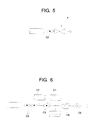
- the single system for high or low pressure gas flow rate control and a high or low pressure gas control valve of this patent application consists essentially of a system (S) which has active control of the movement of the ram (E) of the single valve (1) by the concept of measurement of the flow rate and by the difference in pressure between the inlet and outlet of the said valve (1) which, based on certain predefined parameters, opens or closes the ram (E) in order to compensate the error between the actual and programmed flow rates or the actual and programmed pressure differential.
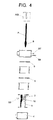
- the system (S) proposed following certain stages (B) that will be described hereunder, substitutes the various measurement components (C1), solenoids (C2), pressure regulation valve (C3), flow meter (C4) and flow regulation valve (C5) in conventional systems, being capable of controlling the ram (E) of a valve (1) located after a solenoid valve (C2), which may be operated by a step engine (A) as well as by an electromagnetic mechanism (B).
- the said system at a first stage (B1) reads the flow rate set point
- at a second stage (B2) converts the flow rate set point into a set point with a pressure differential between the inlet and outlet of the valve
- at a third stage (B3) reads the actual pressure differential
- at a fourth stage (B4) calculates the error between the actual pressure differential in relation to the pressure differential of the set point
- at a fifth stage (B5) seeks the estimated position of the ram of the valve (1)
- at a sixth stage (B6) analyses the tolerance error and takes a decision; if the error is smaller than the tolerance (N), it goes back to the third stage (B3) and if the error is greater than the tolerance (S), it goes back to the fifth stage (B5), i.e. it seeks the estimated position of the ram (E).
- the system can function by establishing a flow rate set point and by converting the pressure differential read in terms of the flow rate and subsequent comparison of the actual flow rate and the flow rate set point.
- the said system (S1) can be described more specifically in that at a first stage (B1') it performs the reading of the flow rate set point, at a second stage (B2') it reads the actual pressure differential, at a third stage (B3') it converts the actual pressure differential into actual flow rate, at a fourth stage (B4') it calculates the error between the measured flow rate in relation to the flow rate set point, at a fifth stage (B5') it seeks the estimated position of the ram of the valve (1), then at a sixth stage (B6') it analyses the tolerance error and takes a decision; if the error is smaller than the tolerance (N), it goes back to the third stage (B3') and if the error is greater than tolerance (S), it goes back to the fifth stage (B5'), i.e. it seek
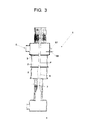
- valve (1) of the invention makes the abovementioned stages (B or B') effective, for which purpose three main regions are formed: one gas admission chamber (2), one Venturi (3) and one outlet chamber (4).
- the gas admission chamber (2) has internally a series of flow rate aligners, which are simply drilled plates (5) that force the passage of the gas or air in the direction of alignment of the Venturi (3).
- the number and size of the said plates (5) are appropriate for the capacity and format of the valve (1).
- the admission (6) of the gas or air it may be parallel (not represented) or orthogonal to the Venturi (3), and at the inlet point there are sensors for measuring pressure (S7) and temperature (S8).
- the Venturi (3) has a conical access (9) whose geometry matches the valve (1), the opening of which is regulated by an passage (10) with a form and dimension coincident with the Venturi (3), which can be activated by a step engine (A) or by an electromagnetic mechanism (B).
- a step engine (A) or by an electromagnetic mechanism (B).
- B an electromagnetic mechanism
- a second sensor (S9) intended to measure the pressure at this point.
- control can be performed not only by the gas flow rate but also by the ambient temperature, for which purpose it is sufficient to install a thermocouple next to the burner, this being the application of the valve which, by an adequate interface, will control the opening and/or closing of the ram (E) of the valve in response to the difference between the measurement of the thermocouple and the projected heating curve.
- thermocouples may be installed inside thereof whose duly worked data would serve as an input for simultaneous control systems with several valves, which would operate the variable opening and closing of the valve rams, thus achieving in the same system the centralized control of the heating in accordance with predefined heating curves.
Landscapes
- Physics & Mathematics (AREA)
- General Physics & Mathematics (AREA)
- Engineering & Computer Science (AREA)
- Automation & Control Theory (AREA)
- Flow Control (AREA)
- Control Of Fluid Pressure (AREA)
Priority Applications (3)
| Application Number | Priority Date | Filing Date | Title |
|---|---|---|---|
| EP06398009A EP1879089A3 (fr) | 2006-07-14 | 2006-07-14 | Système de contrôle du débit de gaz et vanne de commande de gaz |
| DE2006398009 DE06398009T1 (de) | 2006-07-14 | 2006-07-14 | System zur Regelung der Gasdurchflussrate und Gasregelventil |
| ES06398009T ES2324195T1 (es) | 2006-07-14 | 2006-07-14 | Sistema para el control del caudal de gas y valvula de control de gas. |
Applications Claiming Priority (1)
| Application Number | Priority Date | Filing Date | Title |
|---|---|---|---|
| EP06398009A EP1879089A3 (fr) | 2006-07-14 | 2006-07-14 | Système de contrôle du débit de gaz et vanne de commande de gaz |
Publications (2)
| Publication Number | Publication Date |
|---|---|
| EP1879089A2 true EP1879089A2 (fr) | 2008-01-16 |
| EP1879089A3 EP1879089A3 (fr) | 2008-01-23 |
Family
ID=38669587
Family Applications (1)
| Application Number | Title | Priority Date | Filing Date |
|---|---|---|---|
| EP06398009A Ceased EP1879089A3 (fr) | 2006-07-14 | 2006-07-14 | Système de contrôle du débit de gaz et vanne de commande de gaz |
Country Status (3)
| Country | Link |
|---|---|
| EP (1) | EP1879089A3 (fr) |
| DE (1) | DE06398009T1 (fr) |
| ES (1) | ES2324195T1 (fr) |
Citations (1)
| Publication number | Priority date | Publication date | Assignee | Title |
|---|---|---|---|---|
| US4277832A (en) | 1979-10-01 | 1981-07-07 | General Electric Company | Fluid flow control system |
Family Cites Families (3)
| Publication number | Priority date | Publication date | Assignee | Title |
|---|---|---|---|---|
| DE3700898A1 (de) * | 1987-01-14 | 1988-07-28 | Herion Werke Kg | Mengenregelventil |
| DE10001165C2 (de) * | 2000-01-13 | 2003-02-06 | Liebherr Aerospace Gmbh | Durchsatzregelventil mit intelligentem Durchflußmeßsystem |
| US6973375B2 (en) * | 2004-02-12 | 2005-12-06 | Mykrolis Corporation | System and method for flow monitoring and control |
-
2006
- 2006-07-14 DE DE2006398009 patent/DE06398009T1/de active Pending
- 2006-07-14 EP EP06398009A patent/EP1879089A3/fr not_active Ceased
- 2006-07-14 ES ES06398009T patent/ES2324195T1/es active Pending
Patent Citations (1)
| Publication number | Priority date | Publication date | Assignee | Title |
|---|---|---|---|---|
| US4277832A (en) | 1979-10-01 | 1981-07-07 | General Electric Company | Fluid flow control system |
Also Published As
| Publication number | Publication date |
|---|---|
| ES2324195T1 (es) | 2009-08-03 |
| DE06398009T1 (de) | 2009-08-13 |
| EP1879089A3 (fr) | 2008-01-23 |
Similar Documents
| Publication | Publication Date | Title |
|---|---|---|
| US11175039B2 (en) | Regulating turbulent flows | |
| US11149946B2 (en) | System and approach for controlling a combustion chamber | |
| EP3732394B1 (fr) | Programmation et commande en boucle fermée d'appareil de combustion | |
| CN101270880B (zh) | 燃烧加热炉的空气燃料比控制系统 | |
| US10422531B2 (en) | System and approach for controlling a combustion chamber | |
| US10503181B2 (en) | Pressure regulator | |
| GB2504807A (en) | Control of combustion process systems | |
| AU2010246518B2 (en) | Method for reducing NOx emissions from a burner assembly, comprising several burners, and burner assembly for carrying out said method | |
| EP3830483B1 (fr) | Système de combustion à combustible inféré et procédé associé | |
| CN102549349A (zh) | 用于燃烧控制系统的辅助试运转方法 | |
| EP3404326A1 (fr) | Système et approche pour commander une chambre de combustion | |
| EP3608591B1 (fr) | Brûleur | |
| CN107957080A (zh) | 铝棒加热炉燃烧温度自动控制系统 | |
| US7753066B2 (en) | Single system for low or high pressure gases control and high or low pressure gases control valve | |
| EP3617596B1 (fr) | Procédé de fonctionnement d'un appareil à brûleur à gaz | |
| US20250052423A1 (en) | Method and apparatus for monitoring and controlling combustion in combustible gas burner apparatus | |
| Voicu et al. | Digital Control Systems for Thermal Regimes in Industrial Furnaces. | |
| JP2022065370A (ja) | 流量制御システム、及びそれを備えた燃焼制御システム | |
| JP2025146187A (ja) | 流量制御機構、及びそれを備えた燃焼制御システム | |
| CN117405401A (zh) | 一种基于mpc控制技术的定容弹稳压系统 | |
| JPH0560322A (ja) | ガスバーナの制御装置 | |
| JPH08200660A (ja) | 燃焼機器 |
Legal Events
| Date | Code | Title | Description |
|---|---|---|---|
| PUAI | Public reference made under article 153(3) epc to a published international application that has entered the european phase |
Free format text: ORIGINAL CODE: 0009012 |
|
| PUAL | Search report despatched |
Free format text: ORIGINAL CODE: 0009013 |
|
| AK | Designated contracting states |
Kind code of ref document: A2 Designated state(s): AT BE BG CH CY CZ DE DK EE ES FI FR GB GR HU IE IS IT LI LT LU LV MC NL PL PT RO SE SI SK TR |
|
| AX | Request for extension of the european patent |
Extension state: AL BA HR MK YU |
|
| AK | Designated contracting states |
Kind code of ref document: A3 Designated state(s): AT BE BG CH CY CZ DE DK EE ES FI FR GB GR HU IE IS IT LI LT LU LV MC NL PL PT RO SE SI SK TR |
|
| AX | Request for extension of the european patent |
Extension state: AL BA HR MK YU |
|
| 17P | Request for examination filed |
Effective date: 20080605 |
|
| 17Q | First examination report despatched |
Effective date: 20080730 |
|
| AKX | Designation fees paid |
Designated state(s): AT BE BG CH CY CZ DE DK EE ES FI FR GB GR HU IE IS IT LI LT LU LV MC NL PL PT RO SE SI SK TR |
|
| DET | De: translation of patent claims | ||
| STAA | Information on the status of an ep patent application or granted ep patent |
Free format text: STATUS: THE APPLICATION HAS BEEN REFUSED |
|
| 18R | Application refused |
Effective date: 20110429 |