EP1879181B1 - Procédé pour la compensation des composants d'un signal audio dans un système de communication dans une voiture et un système pour ça - Google Patents
Procédé pour la compensation des composants d'un signal audio dans un système de communication dans une voiture et un système pour ça Download PDFInfo
- Publication number
- EP1879181B1 EP1879181B1 EP06014366.6A EP06014366A EP1879181B1 EP 1879181 B1 EP1879181 B1 EP 1879181B1 EP 06014366 A EP06014366 A EP 06014366A EP 1879181 B1 EP1879181 B1 EP 1879181B1
- Authority
- EP
- European Patent Office
- Prior art keywords
- signal
- audio signal
- filter
- audio
- sound
- Prior art date
- Legal status (The legal status is an assumption and is not a legal conclusion. Google has not performed a legal analysis and makes no representation as to the accuracy of the status listed.)
- Not-in-force
Links
Images







Classifications
-
- G—PHYSICS
- G10—MUSICAL INSTRUMENTS; ACOUSTICS
- G10L—SPEECH ANALYSIS TECHNIQUES OR SPEECH SYNTHESIS; SPEECH RECOGNITION; SPEECH OR VOICE PROCESSING TECHNIQUES; SPEECH OR AUDIO CODING OR DECODING
- G10L21/00—Speech or voice signal processing techniques to produce another audible or non-audible signal, e.g. visual or tactile, in order to modify its quality or its intelligibility
- G10L21/02—Speech enhancement, e.g. noise reduction or echo cancellation
-
- G—PHYSICS
- G10—MUSICAL INSTRUMENTS; ACOUSTICS
- G10L—SPEECH ANALYSIS TECHNIQUES OR SPEECH SYNTHESIS; SPEECH RECOGNITION; SPEECH OR VOICE PROCESSING TECHNIQUES; SPEECH OR AUDIO CODING OR DECODING
- G10L21/00—Speech or voice signal processing techniques to produce another audible or non-audible signal, e.g. visual or tactile, in order to modify its quality or its intelligibility
- G10L21/02—Speech enhancement, e.g. noise reduction or echo cancellation
- G10L21/0208—Noise filtering
- G10L2021/02082—Noise filtering the noise being echo, reverberation of the speech
-
- H—ELECTRICITY
- H04—ELECTRIC COMMUNICATION TECHNIQUE
- H04R—LOUDSPEAKERS, MICROPHONES, GRAMOPHONE PICK-UPS OR LIKE ACOUSTIC ELECTROMECHANICAL TRANSDUCERS; ELECTRIC HEARING AIDS; PUBLIC ADDRESS SYSTEMS
- H04R2499/00—Aspects covered by H04R or H04S not otherwise provided for in their subgroups
- H04R2499/10—General applications
- H04R2499/13—Acoustic transducers and sound field adaptation in vehicles
-
- H—ELECTRICITY
- H04—ELECTRIC COMMUNICATION TECHNIQUE
- H04R—LOUDSPEAKERS, MICROPHONES, GRAMOPHONE PICK-UPS OR LIKE ACOUSTIC ELECTROMECHANICAL TRANSDUCERS; ELECTRIC HEARING AIDS; PUBLIC ADDRESS SYSTEMS
- H04R3/00—Circuits for transducers
- H04R3/02—Circuits for transducers for preventing acoustic reaction, i.e. acoustic oscillatory feedback
Definitions
- This invention relates to a vehicle communication system, especially to a method and a system for compensation audio signal components in a vehicle communication system.
- the voice of one of the passengers is detected using one or more microphones which are positioned in different locations in the vehicle.
- the signal detected by the microphone can be processed and then output using the loudspeakers of an audio module which is normally comprised in the vehicle.
- the signal emitted from the loudspeaker is normally also detected by the microphone.
- the signals detected by the microphone have to be processed and such signal components have to be filtered out. Otherwise, an annoying wizzle can occur in the system.
- audio modules In addition to the communication signals output via the loudspeakers of the vehicle, audio modules reproducing audio signals such as radio signals or signals from a music storage such as a compact disc, are provided in the vehicles. These audio signals are output via the same loudspeakers and are also recorded by the microphones and are again output via the loudspeaker. If these audio signal components are not attenuated before the output, the driver has the impression of an audio sound signal having reverberation.
- the above-described vehicle communication systems are often incorporated into expensive highly sophisticated vehicles having highly sophisticated audio components.
- the audio module When the audio module is used in connection with a vehicle communication system, the sound quality is deteriorated by the feedback of the audio signal components picked up by the microphone and again fed to the loudspeakers.
- the audio signal In order to avoid this signal quality degradation, the audio signal should be disabled during the in-vehicle communication, or the audio signal components detected by the microphone should be filtered out in an effective way.
- the compensation of the audio signal components is based on the idea that the filter has to simulate the audio signal components of a sound signal emitted from the loudspeaker and detected by the microphone.
- the audio signal component my be an audio signal of a classical piece of music, a pop music or maybe an interview without music.
- the audio signal components of the audio signal can have, in case of a stereo signal, completely independent audio channels, however, mostly in the case of interviews or one speaking person the two audio signal parts of the stereo signal can be completely linear depending signals.
- the echo compensation for linear dependent signals is a difficult task as the adaptation algorithms for calculating the filter coefficients do not have a well-defined solution.
- the filters also have to be adapted to the new signal characteristics. This adaptation of the filter takes a certain amount of time and during this time none-wanted echoes do occur.
- a need of this invention is to further improve the echo compensation, i.e. the compensation of the audio signal components in a sound signal in a vehicle in a vehicle communication system.
- a method for compensating audio signal components in a vehicle communication system is provided.
- a sound signal in a vehicle is detected by a microphone, the sound signal comprising audio signal components resulting from reproducing an audio signal of an audio source, the sound signal further comprising speech signal components corresponding to a speech signal from a passenger of the vehicle.
- the audio signal component is the signal component by reproducing the audio source
- the speech signal component is the signal component which is to be detected by the microphone in the vehicle communication system.
- the detected sound signal is then filtered in order to whiten the sound signal. The whitening of the sound signal is carried out, as the echo compensation compensating the audio signal component is more effective when it is carried out on a whitened sound signal.
- a whitened signal indicates that the spectrum contains equal power per cycle, i.e. the signal has a flat spectrum which contains all different frequencies in equal amount.
- the filtering for whitening the sound signal furthermore decorrelates the different channels of the audio signal.
- the audio signal is filtered in order to whiten the audio signal.
- the acoustic echoes are compensated by compensating the audio signal components in the sound signal.
- the whitening of the compensated sound signal is removed.
- the filtering of the audio signal for whitening the sound signal is performed using at least two filters in an alternating way, each filter having time-dependent filter coefficients. When time-dependent filter coefficients are used, the actual characteristic of the audio signal can be taken into account.
- the filtering can now be adapted to the actual audio signal. Due to the fact that time-dependent filter coefficients are used, at least two different filters are used in an alternating way. When one filter is actually used for filtering, the other filter continues receiving the audio signal so that filter coefficients for this new part of the audio signal can be calculated. With the use of time-dependent filter coefficients, the actual speed of the echo compensation filter compensating the audio signal components can be improved. Furthermore, the use of two different filters in an alternating way helps to keep the signal processing power low.
- the radio signal of the left audio channel x L (n) and of the right audio channel x R (n) are output via a loudspeaker and reach the microphone after having passed the interior of the vehicle.
- the audio signal component detected by the microphone comprises the direct audio signal and comprises signal components which were diffracted by an obstacle in the path of the sound.
- h L n [ h L , 0 n , h L , 1 n , ... , h L , L - 1 n ⁇ ] T
- h L n [ h R , 0 n , h R , 1 n , ... , h R , L - 1 n ⁇ ] T .
- the index n should indicate the time dependence of the pulse response.
- the signal path from the loudspeaker to the microphone has to be simulated by filtering the audio signal in such a way that after filtering the filtered audio signal corresponds more or less to the audio signal as it was detected by the microphone. If this is the case, the audio signal component can be removed from the sound signal by simply subtracting the simulated audio signal component from the detected sound signal.
- h ⁇ L n [ h ⁇ L , 0 n , h ⁇ L , 1 n , ... , h ⁇ L , L - 1 n ⁇ ] T
- h ⁇ L n [ h ⁇ R , 0 n , h ⁇ R , 1 n , ... , h ⁇ R , L - 1 n ⁇ ] T .
- the signal d(n) is either the signal from the microphone or the signal of a linear time invariant processing.
- a good compensation of the audio signal component can be achieved when the estimated pulse response corresponds to the actual pulse responses and when a sufficient number of coefficients were used.
- the left and the right audio signals can have very different cross correlation characteristics.
- C ⁇ S XLXR ⁇ S XLXL ⁇ ⁇ S XRXR ⁇ 2 normally has values C ( ⁇ ) ⁇ 1, whereas by reproducing news or one speaker the left and the right audio signal can be completely linear dependent signals, meaning that the coherence is more or less 1.
- the value S xLxR ( ⁇ ), S xLxL ( ⁇ ) and S xRxR ( ⁇ ) are called the cross power spectral density or auto power spectral density of the left and right signals x L (n) and x R (n).
- the adaptation algorithm compensating the acoustic echoes does not have a non-ambiguous single solution.
- the audio signal of the audio signal source is supplied to a calculation unit where the time-dependent filter coefficients are calculated for the decorrelation filters.
- the time-dependent filter coefficient of the coefficient calculation unit are then used for whitening the sound signal comprising both signal components (the audio signal component and the speech signal component) and are used for whitening the audio signal that is output from the loudspeakers.
- the calculated filter coefficients are calculated based on the audio signal itself and are supplied to a sound signal filter filtering the detected sound signal, the filter coefficients of the sound signal filter being renewed every N cycles, N being the length of the compensation filter. Additionally, the calculated filter coefficients are supplied to two audio filters whitening the audio signal in an alternating way.
- each of the audio signal filters whitening the audio signal is connected to an echo compensator compensating the acoustic echoes of the length N where the signal path of the audio signal is simulated.
- the whitened simulated audio signal from the two filters is supplied to a subtracting unit where the simulated audio signal components are subtracted from the whitened sound signal comprising the two components. The result of this subtraction is then a whitened error signal ⁇ ( n ).
- This whitened error signal is then used as a feedback control signal controlling the determination of the estimated sound signal component. Additionally, the whitened error signal can then be supplied to an inverse filter removing the whitening from the whitened error signal resulting in an error signal corresponding to the echo compensated sound signal in which the audio signal components were suppressed.
- time-dependent filter coefficients are used, so that new filter parameters are calculated every 2N cycles.
- the whitened simulated audio signal of each filter is then supplied to a switch, the switch changing every N cycles from one echo compensation filter to the other from where the signal is transmitted to the subtracting unit where it is subtracted from the whitened sound signal.
- the invention further relates to an echo compensation system for compensation audio signal components in a vehicle communication system comprising at least one microphone receiving the sound signal having the two signal components described above. Additionally, a loudspeaker is provided outputting the sound signal detected by the microphone and outputting the audio signal itself. Due to the fact that the audio signal is output twice, once directly and once as it is detected by the microphone, the audio signal component has to be removed from the sound signal detected by the microphone. To this end, an echo compensation unit compensating the audio signal components of the sound signal is provided and a filter for whitening the sound signal and the audio signal.
- the filter unit for whitening the sound signal and the audio signal comprises at least two audio sound filters each of them using time-dependent filter coefficients, the two filters being used in an alternating way for filtering the audio signal.
- a calculating unit may be provided calculating the time-dependent filter coefficients. Additionally, a first switch switching the supply of the time-dependent filter coefficients to either one of the two audio signal filters is provided. Furthermore, a second switch may be provided which supplies the simulated audio signal components to a subtraction unit. Last but not least, an inverse filter is provided removing the whitening of the whitened error signal resulting in the echo compensated sound signal, this inverse filter also being connected to the filter coefficient calculating unit calculating the time-dependent filter coefficients.
- the echo compensation unit comprises two audio sound filters and two echo compensators for each audio channel of the audio signal.
- FIG. 1 an in-vehicle communication system is shown in which the echo compensation according to the invention may be used.
- Such an in-vehicle communication system normally comprises a plurality of loudspeakers 11 emitting the audio signal from an audio source 15.
- loudspeakers 11 emitting the audio signal from an audio source 15.
- the position 12a of the driver the position on the front seat next to the driver 12b and two positions in the back 12c and 12d.
- microphones or a ray of microphones 13a for picking up the speech signal of the driver When one of the passengers in the front wants to communicate with one of the passengers sitting in the back or if two passengers, one in the front and one in the back, are communicating with a third person in a telecommunication system, microphones or a ray of microphones 13a for picking up the speech signal of the driver, microphone 13b picking up the speech signal of the other front passenger, microphone 13c picking up the speech signal of the passenger in the back behind the driver and microphone 13d picking up the speech signal on the passenger in the back on the right side are provided.
- a beam forming for the different vehicle seat positions can be done.
- the signals received from the microphones 13c-13d are supplied to a first signal processing unit 16 controlling the signal processing from the speech signals from the back seat to the front seat, whereas a signal processing unit 17 (connected with the microphones 13a - 13b) controls the signal processing from the front seat to the back seat.
- the signal processing unit 16 and 17 determines through which loudspeakers of the vehicle the signal detected by the microphone should be output to the different passengers.
- a unit 15 represents the audio signal source of Fig. 1 having two different audio channels, a first channel x L (n) and a second channel x R (n).
- a two channel audio signal is shown, however, the system also works for a multiple channel audio signal.
- the two audio signals are then transmitted to a filter unit 21 where the audio signals are either filtered in a time-variant manner or processed by a nonlinear characteristic in order to reduce the mutual correlation.
- This unit is an optional unit.
- the preprocessed audio signal is then transmitted to an audio amplifier 22 amplifying the signals before they are emitted via the loudspeakers 11.
- the whitened audio signal components are also supplied to an echo compensation unit 23 where the audio signal components of a detected sound signal should be removed.
- the audio signal emitted from the loudspeakers 11 propagate in the vehicle and may be diffracted in the vehicle different times before they are detected by the microphone 13.
- the detected sound signal comprising audio signal components as emitted by the loudspeaker and also comprising speech signal components from one of the passengers is then fed to a processing unit 24 where a linear processing (beam forming etc.) can be done.
- the output signal of the two units 23 and 24 are then fed to a subtracting unit 25 where the simulated signal component of unit 23 is subtracted from the detected signal.
- the subtraction results in an error signal as discussed in the introductory part of the description.
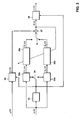
- Fig. 3 an echo compensation system using time-dependent filter coefficients is shown in more detail.
- the sound signal as detected by the microphone is shown by y(n)
- the audio signal itself i.e. one channel of the audio signal
- time-dependent decorrelation filter coefficients are used.
- a calculating unit 31 is provided where the time-dependent filter decorrelation coefficients are calculated.
- the system of Fig. 3 furthermore comprises several decorrelation filters for whitening the different signals.
- a first decorrelation filter 32 is provided for whitening the sound signal as detected by the microphone.
- decorrelation filters 33a and 33b are provided, which are used for filtering the audio signal itself.
- the decorrelation filters 32 and 33a and 33b are used to decorrelate the different signal channels of the audio signals.
- the audio signal is processed in intervals and for each interval the filter coefficients are calculated.
- the filter coefficient of the first interval e.g. an audio signal of 100 ms and the corresponding filter coefficients are supplied to the first filter 33a through a switch 34.
- the switch 34 switches to the second filter 33b, and the calculated filter coefficients calculated by unit 31 are transmitted to the other decorrelation filter 33b.
- the switch 34 switches every N cycles, N being the length of the echo compensation filters 35a and 35b.
- N being the length of the echo compensation filters 35a and 35b.
- the echo compensation filter 35b is used for the actual echo compensation.
- the switch 34 changes its position and transmits the calculated filter coefficients to the filter 33b.
- the audio signals are filtered in such a way that the signal path in the vehicle is simulated.
- the echo compensation filters try to determine the pulse response between the loudspeaker and the microphone. This can be done by using gradient methods and using least mean square (LMS) algorithms or normalized least mean square algorithms (NLMS). These compensation methods are known in the art and will not be discussed in detail.
- LMS least mean square
- NLMS normalized least mean square algorithms
- Switches 34 and 36 are controlled in such a way that they are never connected to the same filter.
- the two switches 34 change its state every N cycles, however, both switches always have a different actual state.
- the switch 34 supplies data to the upper branch 33a and 35a
- the switch 36 receives signal data from the lower branch 33b and 35b.
- the signal parameter in the filters 33a and 33b are renewed every 2N cycles, whereas the signal parameters in the filter 32 are renewed every N cycles.
- the output signal of filter 32 and the output signal of the filter 35a or 35b are then used in the subtracting unit where the simulated signal from the echo compensation filters is subtracted from the filtered sound signal as detected by the microphone. The result is a whitened error signal ⁇ ( n ).
- this whitened error signal is then used as a feedback control signal in order to adapt the audio signal compensation filters.
- the whitened error signal is then transmitted to an inverse filter 38 removing the decorrelation.
- This decorrelation filter 38 also receives the calculated filter parameters every N cycles.
- the resulting error signal then corresponds to the signal which will be output through the loudspeakers of the communication system.
- the audio signal component is removed or at least suppressed.
- Fig. 4 the different steps of the echo compensation are summarized.
- the audio signal is output via the loudspeakers (step 42).
- a microphone detecting the voice signal of the passenger also detects the audio signal components.
- the detected sound signal detected in step 43 comprises two different components the audio signal component and a speech signal component.
- the sound signal and the audio signal is whitened in step 44 in order to remove any correlation between different channels of the audio signal.
- the echo compensation is carried out as explained in connection with Fig. 3 using time-dependent decorrelation filter coefficients and using alternating compensation units. After the filtering of the audio signal component, the whitening of the different signals is removed in step 46 resulting in an improved error signal.
- the method shown in Fig. 4 ends in step 47.
- the calculated filter parameters calculated by calculation unit 31 are calculated every 500 cycles (step 51).
- the decorrelation filter coefficients based on the last 500 input samples are transmitted to the decorrelation filter 33a (step 52).
- the other echo cancellation filter is used for the next N cycles (step 52a).
- the calculated filter parameters calculated for the next N cycles are calculated in step 53 and are then transmitted to the other decorrelation filter 33b (step 54).
- the first echo cancellation filter is used (step 54a).
- the filter coefficients are supplied to the decorrelation filter 33a as shown in Fig. 3
- the filter coefficients calculated the N cycles before are used for decorrelation and for suppressing the audio signal component in filter 33b and 35b as also shown in Fig. 3 .
- the echo compensation filters 35 store in the memory of the filter the signals which were decorrelated with old filter parameters.
- the signal processing is shown for one channel of the audio signal x(n).
- this structure of the two filter branches together with the two switches can be applied for every audio channel.
- the channel shown could be the left channel of a stereo signal.
- another filter coefficient calculating unit would be necessary and another two branches of filters.
- the other filtered audio signal channel would be combined with the first audio channel before the signal is transmitted to the subtracting unit 37.
- the detected sound signal comprises all different audio channels. Accordingly, every channel has to be processed as shown in Fig. 3 , the different channels being combined before they are transmitted to the subtracting unit 37.
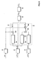
- Fig. 6 an echo compensation system according to another aspect of the invention is shown.
- a mono echo compensation and a stereo echo compensation is carried out at the same time and the compensation achieving the better results is used.
- the signal y(n) is the signal detected by the microphones comprising the audio signal component and the speech signal component.
- the detected sound signal is supplied to a decorrelation filter 61 for whitening the detected sound signal.
- the echo compensation of a stereo signal is shown.
- the stereo signal has a first audio channel x L (n) and the second audio channel x R (n). These two signals are supplied to decorrelation filters 61 for whitening the audio signal as was discussed in connection with Fig. 3 .
- the whitened left audio signal is then input into a mono echo compensation unit 62 and to a stereo echo compensation unit 63.
- the mono echo compensation unit 62 comprises an echo compensation unit 621 where the audio signal component of the sound signal as detected by the microphone is simulated.
- the simulated audio signal is then input into a subtracting unit 620 where it is subtracted from the whitened sound signal resulting in a whitened mono error signal ⁇ M ( n ).
- the left audio channel is, after passing the decorrelation filter 61, also input into the stereo echo compensation unit 63 where it is fed to an echo compensation unit 631 where the signal path is simulated as in the other echo compensation unit 621 and as described in connection with Figs. 1-5 .
- the whitened audio channel is, after passing the decorrelation filter, fed to a second signal compensation unit 632.
- the output signals of the two echo compensation units 631 and 632 are combined in the adder 633 before this combined signal is subtracted from the whitened sound signal in subtracting unit 634.
- the output signal of the subtracting unit 634 is a whitened stereo error signal ⁇ s ( n ).
- the system of Fig. 6 now has two output error signals, a mono error signal and a stereo error signal. Depending on the actual composition of the audio signal either the mono echo compensation unit or the stereo echo compensation unit achieves the better result in removing the audio signal component in the detected sound signal.
- the mono echo compensation unit When the audio signal is a mono signal or a linear dependent stereo signal, the mono echo compensation unit will achieve better compensation results. Additionally, the mono echo compensation is faster. When the audio signal is a stereo signal having non-linear dependent signal components, the stereo echo compensation unit will be able to compensate acoustic echoes.
- a comparison unit 65 In order to compare the two signals a comparison unit 65 is provided having two inputs, one input being the output of the mono echo compensation unit, one input being the output of the stereo echo compensation unit. Comparison unit 65 compares the signal power of the two error signals and selects the signal having the lower signal power as an output signal ⁇ ( n ). This output signal of the comparison unit is then transmitted to an inverse decorrelation filter unit 66 removing the whitening of the echo compensated signal.
- the output error signal e(n) is then the signal which might be output by the loudspeakers in which the audio signal components were effectively removed.
- the echo compensation unit shown in Fig. 6 can be single filters compensating the echo. However, it is also possible to combine the mono and the multi channel echo compensation with the time-dependent filter coefficients described in connection with Figs. 1-5 . This means that for each audio channel a filter coefficient calculating unit such as unit 31 would be provided, and each of the echo compensation units 621, 631 and 632 would be an echo compensation unit as shown in Fig. 3 comprising a switch supplying the calculated decorrelation filter coefficients to one of the two branches of each echo compensation unit, another switch being provided for supplying the echo compensated signal to the subtracting unit. In this embodiment of the invention the time-dependent filter coefficients would be combined with the mono and multi channel echo compensation units.
- Fig. 7 the different steps of the mono and multi channel echo compensation are summarized after starting the process.
- the audio signal is output via the loudspeaker in step 72.
- step 73 the sound signal is detected by the microphone, the sound signal having the speech signal component and the audio signal component.
- One channel of the audio signal is supplied to a mono echo compensation unit in step 74, and in step 75 all channels of the multi channel audio signal are supplied to a multi channel echo compensation unit.
- the echo compensation is carried out, be it with time invariant decorrelation filter coefficients or be it in connection with time-dependent decorrelation filter coefficients as described in connection with Figs. 1-5 .
- step 76 the output of the mono echo compensation unit is compared to the output of the multi channel echo compensation unit.
- step 77 the signal output having the lower signal power is selected and used as an echo compensated output signal of the sound signal detected by the microphones.
- the method ends in step 78.
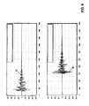
- Fig. 8 two different pulse responses are shown, the upper graph 81 of Fig. 8 showing a pulse response of a stereo amplification modus, whereas the lower part of Fig. 8 shows a graph 82 of a pulse response of an audio signal in a surround sound mode.
- An echo compensation unit now has to simulate the different situations of signal emission and signal reception. If the echo compensation filter were to simulate graph 82, a large echo compensation filter of important length would be necessary.
- Fig. 9 a part of an echo compensation unit is shown which is able to simulate different time delays.
- the echo compensation filter comprises a delay memory 92 receiving the audio signal or excitation signal 91.
- the delay memory is of variable length.
- the delay element introduces a variable delay, before the audio signal is transmitted to a signal memory 93 of the echo compensation filter.
- a memory 94 for storing the filter coefficients of the adaptive filter is provided. As it is known to the skilled person, different entries of the signal memory 93 are multiplied with the filter coefficients and the different terms are added in an adder 94, resulting in an output signal of the adapted filter.
- Graph 95 shows the pulse response calculated by the filter.
- the maximum of the pulse response is located at a filter coefficient having quite a large number. At the beginning the filter coefficients are 0. This pulse response was calculated based on the predetermined length of the delay memory. Above, the delay memory of the part 91a of the audio signal 91 is shown, which is comprised in the delay memory. The other part 91 b of the audio signal 91 is comprised in the signal memory of the filter. With the length of the delay memory shown in Fig. 9 a pulse response is calculated as shown by graph 95 having a maximum 95a, which is located at a filter coefficient having a larger number than desired. When the pulse response 95 is interpreted, one can deduce from the position of the maximum of the pulse response that the time delay introduced by the delay memory was to short.
- the pulse response When it is detected that the maximum 95a of the pulse response is not located at a predetermined filter coefficient, the pulse response is shifted as shown in Fig. 10 .
- the pulse response By shifting the pulse response as shown by graph 105, so that the maximum 105a is located at a predetermined position of the filter coefficients, the non-existing parts of the pulse response can be filled with zeroes as shown by the part 105b of the graph 105.
- the length of the delay element is also adjusted. In the embodiment shown the length of the delay element is increased, so that a larger part 91 c of the audio signal is now comprised in the delay element, whereas only a smaller part of the audio signal 91d is now comprised in the signal memory of the filter.
- the new parts of the audio signal generated by the increasing length of the delay memory can be filled with zeros as represented by part 91e of the graph shown in Fig. 10 .
- the length of the delay element can be controlled in such a way that the maximum of the pulse response is located at a filter coefficient which has a number around 30. It should be understood that any other number can be selected.
- the number of the filter coefficient at which the maximum of the pulse response should be located should be selected in such a way that this filter coefficient is positioned at the beginning of the filter length. If the number is selected to be too small, the system cannot precisely detect whether the determined maximum of the pulse response is actually the maximum or whether the maximum is not represented in the filter coefficients. By way of example, if it is detected that the maximum of the pulse response is located within the first ten filter coefficients, it can be followed that the time delay introduced by the delay element is too large. Accordingly, the length of the delay memory has to be shortened and the impulse response has to be shifted, i.e. the filter coefficients in the coefficient memory 94 have to be shifted. Again, the added parts generated by the shifting are filled with zeroes.
- the calculating power can be used in order to adapt the length of the delay element by calculating the position of the maximum of the pulse response, by verifying whether this position is within a predetermined range and if not, by shifting the pulse response and by adapting the length of the delay element accordingly.
- This invention provides three different aspects, every aspect improving the echo compensation in a vehicle compensation system which is used in connection with an audio system in a vehicle. As discussed above, the different aspects can be used alone or in combination.
Landscapes
- Engineering & Computer Science (AREA)
- Human Computer Interaction (AREA)
- Quality & Reliability (AREA)
- Signal Processing (AREA)
- Health & Medical Sciences (AREA)
- Audiology, Speech & Language Pathology (AREA)
- Computational Linguistics (AREA)
- Physics & Mathematics (AREA)
- Acoustics & Sound (AREA)
- Multimedia (AREA)
- Circuit For Audible Band Transducer (AREA)
- Cable Transmission Systems, Equalization Of Radio And Reduction Of Echo (AREA)
- Fittings On The Vehicle Exterior For Carrying Loads, And Devices For Holding Or Mounting Articles (AREA)
- Stereophonic System (AREA)
Claims (19)
- Procédé de compensation de composants de signal audio dans un système de communication de véhicule, comprenant les étapes de :- la détection, par un microphone (11), d'un signal sonore dans un véhicule, le signal sonore comprenant des composants de signal audio découlant d'une reproduction d'un signal audio d'une source audio dans le véhicule, le signal sonore comprenant en outre des composants de signal vocal correspondant à un signal vocal émanant d'un passager du véhicule,- le filtrage du signal sonore afin de blanchir le signal sonore,- le filtrage du signal audio afin de blanchir le signal audio,- la compensation des composants de signal audio dans le signal sonore blanchi,- la suppression du blanchiment du signal sonore compensé,dans lequel le filtrage du signal audio est effectué en utilisant au moins deux filtres en alternance, chaque filtre utilisant des coefficients de filtre dépendant du temps, dans lequel les coefficients de filtre sont fournis à deux filtres de signal audio (33a, 33b) pour blanchir le signal audio, les coefficients de filtre étant fournis pendant N cycles à l'un des filtres et les coefficients de filtre étant fournis pendant les N cycles suivants à l'autre filtre pour filtrer le signal audio, de sorte que les coefficients de filtre de chacun desdits filtres de signal audio blanchissant le signal audio soient renouvelés tous les 2N cycles.
- Procédé selon la revendication 1, caractérisé en ce qu'il comprend en outre l'étape de la fourniture du signal audio à une unité de calcul où les coefficients de filtre dépendant du temps pour le blanchiment du signal sonore sont calculés.
- Procédé selon la revendication 1 ou 2, dans lequel les coefficients de filtre dépendant du temps sont utilisés pour blanchir le signal sonore comprenant les composants de signal audio et les composants de signal vocal et pour blanchir le signal audio.
- Procédé selon la revendication 2 ou 3, dans lequel les coefficients de filtre calculés sont fournis à un filtre de signal sonore (32) filtrant le signal sonore détecté, les coefficients de filtre dudit filtre de signal sonore étant renouvelés tous les N cycles.
- Procédé selon l'une quelconque des revendications précédentes, dans lequel des échos acoustiques sont compensés en simulant les composants de signal audio du signal sonore au fur et à mesure de leur détection par le microphone et en soustrayant les composants de signal audio simulés au signal sonore détecté comprenant le composant de signal audio et le composant de signal vocal, en engendrant un signal d'erreur.
- Procédé selon la revendication 5, dans lequel le signal d'erreur est utilisé en tant que signal de commande de rétroaction pour déterminer le composant de signal sonore estimé.
- Procédé selon la revendication 5 ou 6, dans lequel chaque filtre de signal audio (33a, 33b) blanchissant le signal audio est relié à un compensateur d'écho (35a, 35b) de la longueur N, où les composants de signal audio sont simulés.
- Procédé selon l'une quelconque des revendications précédentes, dans lequel le signal sonore blanchi est fourni à une unité de soustraction (37) et les signaux audio simulés blanchis provenant des deux filtres sont fournis à l'unité de soustraction (37) en alternance, les composants de signal audio simulés blanchis étant soustraits au signal audio blanchi, en engendrant un signal d'erreur blanchi.
- Procédé selon la revendication 8, dans lequel le signal d'erreur blanchi est fourni à un filtre inverse supprimant le blanchiment du signal d'erreur blanchi, en engendrant un signal d'erreur correspondant au signal sonore compensé d'écho.
- Procédé selon l'une quelconque des revendications 5 à 9, dans lequel le signal audio simulé blanchi de chaque filtre est fourni à un commutateur, le commutateur fournissant l'un des signaux audio simulés à l'unité de soustraction, le commutateur commutant tous les N cycles.
- Système de compensation d'écho pour compenser un écho dans un système de communication de véhicule, comprenant :- au moins un microphone (13) destiné à recevoir un signal sonore, le signal sonore comprenant des composants de signal audio découlant d'une reproduction d'un signal audio d'une source audio dans le véhicule, le signal sonore comprenant en outre des composants de signal vocal correspondant à un signal vocal d'un passager du véhicule,- au moins un haut-parleur (11) destiné à délivrer le signal sonore comprenant les composants de signal audio et les composants de signal vocal et à délivrer le signal audio,- une unité de filtre (32, 33) destinée à blanchir le signal sonore et le signal audio,- une unité de compensation d'écho (35) destinée à compenser les composants de signal audio du signal sonore reçu par le microphone,dans lequel l'unité de filtre comprend au moins deux filtres de signal audio (33a, 33b), chacun d'eux utilisant des coefficients de filtre dépendant du temps pour blanchir le signal audio, lesdits deux filtres étant utilisés en alternance pour filtrer le signal audio, le système comprenant en outre un premier commutateur (34), le premier commutateur étant destiné à fournir les coefficients de filtre dépendant du temps à l'un ou à l'autre des deux filtres de signal audio, dans lequel le commutateur (34) est destiné à commuter d'un filtre de signal audio à l'autre tous les N cycles, de sorte que les coefficients de filtre dépendant du temps de chaque filtre de signal audio soient actualisés tous les 2N cycles.
- Système de compensation d'écho selon la revendication 11, caractérisé en ce qu'il comprend en outre une unité de calcul (31) destinée à calculer les coefficients de filtre dépendant du temps pour blanchir le signal sonore sur la base du signal audio.
- Système de compensation d'écho selon l'une quelconque des revendications 11 et 12, caractérisé en ce que l'unité de filtre comprend en outre un filtre de signal sonore destiné à recevoir les coefficients de filtre dépendant du temps calculés par l'unité de calcul, les coefficients de filtre dudit filtre de signal sonore étant actualisés tous les N cycles.
- Système de compensation d'écho selon l'une quelconque des revendications 11 à 13, caractérisé en ce que l'unité de compensation d'écho comprend au moins deux compensateurs d'écho (35a, 35b), dans lequel chaque compensateur d'écho est relié à l'un des filtres de signal audio (33a, 33b) et est destiné à recevoir un signal audio blanchi en provenance d'un filtre de signal audio et est destiné à simuler les composants de signal audio du signal sonore au fur et à mesure de leur détection par le microphone (13).
- Système de compensation d'écho selon la revendication 14, caractérisé en ce que l'unité de compensation d'écho comprend en outre une unité de soustraction (37) où les composants de signal audio simulés blanchis sont soustraits au signal sonore blanchi, en engendrant un signal d'erreur blanchi.
- Système de compensation d'écho selon la revendication 15, caractérisé en ce que le signal d'erreur blanchi est utilisé en tant que signal de commande de rétroaction pour les compensateurs d'écho.
- Système de compensation d'écho selon l'une quelconque des revendications 11 à 16, caractérisé en ce qu'il comprend en outre un filtre inverse (38) pour supprimer le blanchiment du signal d'erreur blanchi, en engendrant un signal sonore compensé d'écho, le filtre inverse recevant les coefficients de filtre calculés.
- Système de compensation d'écho selon l'une quelconque des revendications 11 à 17, caractérisé en ce qu'il comprend deux filtres de signal audio, et deux compensateurs d'écho pour chaque canal audio du signal audio.
- Système de compensation d'écho selon l'une quelconque des revendications 11 à 18, caractérisé en ce qu'il comprend en outre un deuxième commutateur (36) fournissant l'un des composants de signal audio simulés des deux compensateurs d'écho à l'unité de soustraction, le commutateur commutant tous les N cycles.
Priority Applications (4)
| Application Number | Priority Date | Filing Date | Title |
|---|---|---|---|
| EP06014366.6A EP1879181B1 (fr) | 2006-07-11 | 2006-07-11 | Procédé pour la compensation des composants d'un signal audio dans un système de communication dans une voiture et un système pour ça |
| JP2007154363A JP5166777B2 (ja) | 2006-07-11 | 2007-06-11 | 車両通信システムにおけるオーディオ信号コンポーネントを補償するための方法およびそのためのシステム |
| US11/776,432 US20080015845A1 (en) | 2006-07-11 | 2007-07-11 | Audio signal component compensation system |
| US13/368,092 US9111544B2 (en) | 2006-07-11 | 2012-02-07 | Mono and multi-channel echo compensation from selective output |
Applications Claiming Priority (1)
| Application Number | Priority Date | Filing Date | Title |
|---|---|---|---|
| EP06014366.6A EP1879181B1 (fr) | 2006-07-11 | 2006-07-11 | Procédé pour la compensation des composants d'un signal audio dans un système de communication dans une voiture et un système pour ça |
Publications (2)
| Publication Number | Publication Date |
|---|---|
| EP1879181A1 EP1879181A1 (fr) | 2008-01-16 |
| EP1879181B1 true EP1879181B1 (fr) | 2014-05-21 |
Family
ID=37256674
Family Applications (1)
| Application Number | Title | Priority Date | Filing Date |
|---|---|---|---|
| EP06014366.6A Not-in-force EP1879181B1 (fr) | 2006-07-11 | 2006-07-11 | Procédé pour la compensation des composants d'un signal audio dans un système de communication dans une voiture et un système pour ça |
Country Status (3)
| Country | Link |
|---|---|
| US (2) | US20080015845A1 (fr) |
| EP (1) | EP1879181B1 (fr) |
| JP (1) | JP5166777B2 (fr) |
Families Citing this family (25)
| Publication number | Priority date | Publication date | Assignee | Title |
|---|---|---|---|---|
| DE102008039330A1 (de) | 2008-01-31 | 2009-08-13 | Fraunhofer-Gesellschaft zur Förderung der angewandten Forschung e.V. | Vorrichtung und Verfahren zum Berechnen von Filterkoeffizienten zur Echounterdrückung |
| JP5410720B2 (ja) | 2008-09-25 | 2014-02-05 | 日立コンシューマエレクトロニクス株式会社 | ディジタル情報信号送受信装置、およびディジタル情報信号送受信方法 |
| TWI465122B (zh) | 2009-01-30 | 2014-12-11 | Dolby Lab Licensing Corp | 自帶狀脈衝響應資料測定反向濾波器之方法 |
| GB2465047B (en) | 2009-09-03 | 2010-09-22 | Peter Graham Craven | Prediction of signals |
| CN102549660B (zh) * | 2009-10-01 | 2014-09-10 | 日本电气株式会社 | 信号处理方法和信号处理装置 |
| JP5649488B2 (ja) * | 2011-03-11 | 2015-01-07 | 株式会社東芝 | 音声判別装置、音声判別方法および音声判別プログラム |
| JP2013030868A (ja) * | 2011-07-27 | 2013-02-07 | Sony Corp | エコー除去装置、エコー除去方法、プログラムおよび記録媒体 |
| EP2850611B1 (fr) * | 2012-06-10 | 2019-08-21 | Nuance Communications, Inc. | Traitement du signal dépendant du bruit pour systèmes de communication à l'intérieur d'une voiture avec plusieurs zones acoustiques |
| EP2859772B1 (fr) | 2012-06-10 | 2018-12-19 | Nuance Communications, Inc. | Détection du bruit caractéristique du vent pour les systèmes de communication embarqués comportant plusieurs zones acoustiques |
| US9497544B2 (en) | 2012-07-02 | 2016-11-15 | Qualcomm Incorporated | Systems and methods for surround sound echo reduction |
| CN103067821B (zh) * | 2012-12-12 | 2015-03-11 | 歌尔声学股份有限公司 | 一种基于双麦克的语音混响消减方法和装置 |
| WO2014168618A1 (fr) * | 2013-04-11 | 2014-10-16 | Nuance Communications, Inc. | Système pour la reconnaissance vocale automatique et les divertissements audio |
| US9613634B2 (en) * | 2014-06-19 | 2017-04-04 | Yang Gao | Control of acoustic echo canceller adaptive filter for speech enhancement |
| US20160127827A1 (en) * | 2014-10-29 | 2016-05-05 | GM Global Technology Operations LLC | Systems and methods for selecting audio filtering schemes |
| US9672805B2 (en) * | 2014-12-12 | 2017-06-06 | Qualcomm Incorporated | Feedback cancelation for enhanced conversational communications in shared acoustic space |
| KR102507151B1 (ko) * | 2015-08-27 | 2023-03-08 | 티씨엘 차이나 스타 옵토일렉트로닉스 테크놀로지 컴퍼니 리미티드 | 표시 장치 및 그 제조 방법 |
| US9691378B1 (en) * | 2015-11-05 | 2017-06-27 | Amazon Technologies, Inc. | Methods and devices for selectively ignoring captured audio data |
| CN110024421B (zh) | 2016-11-23 | 2020-12-25 | 瑞典爱立信有限公司 | 用于自适应控制去相关滤波器的方法和装置 |
| US10079015B1 (en) | 2016-12-06 | 2018-09-18 | Amazon Technologies, Inc. | Multi-layer keyword detection |
| WO2018186779A1 (fr) * | 2017-04-07 | 2018-10-11 | Dirac Research Ab | Nouvelle égalisation paramétrique pour des applications audio |
| US10291996B1 (en) * | 2018-01-12 | 2019-05-14 | Ford Global Tehnologies, LLC | Vehicle multi-passenger phone mode |
| CN112840670B (zh) * | 2018-09-07 | 2022-11-08 | 杜比实验室特许公司 | 媒体补偿直通装置中的动态环境叠加不稳定性检测及抑制 |
| DE102019105458B4 (de) * | 2019-03-04 | 2021-06-10 | Harman Becker Automotive Systems Gmbh | System und Verfahren zur Zeitverzögerungsschätzung |
| US10984815B1 (en) * | 2019-09-27 | 2021-04-20 | Cypress Semiconductor Corporation | Techniques for removing non-linear echo in acoustic echo cancellers |
| CN111031448B (zh) * | 2019-11-12 | 2021-09-17 | 西安讯飞超脑信息科技有限公司 | 回声消除方法、装置、电子设备和存储介质 |
Family Cites Families (26)
| Publication number | Priority date | Publication date | Assignee | Title |
|---|---|---|---|---|
| US5305307A (en) * | 1991-01-04 | 1994-04-19 | Picturetel Corporation | Adaptive acoustic echo canceller having means for reducing or eliminating echo in a plurality of signal bandwidths |
| US5555310A (en) * | 1993-02-12 | 1996-09-10 | Kabushiki Kaisha Toshiba | Stereo voice transmission apparatus, stereo signal coding/decoding apparatus, echo canceler, and voice input/output apparatus to which this echo canceler is applied |
| SE501248C2 (sv) * | 1993-05-14 | 1994-12-19 | Ericsson Telefon Ab L M | Metod och ekosläckare för ekoutsläckning med ett antal kaskadkopplade adaptiva filter |
| GB2281680B (en) * | 1993-08-27 | 1998-08-26 | Motorola Inc | A voice activity detector for an echo suppressor and an echo suppressor |
| DE19814971A1 (de) * | 1998-04-03 | 1999-10-07 | Daimlerchrysler Aerospace Ag | Verfahren zur Störbefreiung eines Mikrophonsignals |
| JP3837685B2 (ja) * | 1998-10-07 | 2006-10-25 | 富士通株式会社 | 能動雑音制御方法及び受話装置 |
| KR100307662B1 (ko) * | 1998-10-13 | 2001-12-01 | 윤종용 | 가변적인수행속도를지원하는에코제거장치및방법 |
| US6263078B1 (en) * | 1999-01-07 | 2001-07-17 | Signalworks, Inc. | Acoustic echo canceller with fast volume control compensation |
| JP2000209135A (ja) * | 1999-01-20 | 2000-07-28 | Oki Electric Ind Co Ltd | エコ―キャンセラ |
| US6510225B1 (en) * | 1999-02-16 | 2003-01-21 | Denso Corporation | Ultrasonically-calibrated fast-start echo canceller for cellular and pcs telephone car kits |
| US6580696B1 (en) * | 1999-03-15 | 2003-06-17 | Cisco Systems, Inc. | Multi-adaptation for a voice packet based |
| FR2793629B1 (fr) * | 1999-05-12 | 2001-08-03 | Matra Nortel Communications | Procede et dispositif d'annulation d'echo stereophonique a filtrage dans le domaine frequentiel |
| DE10153188C2 (de) * | 2001-10-27 | 2003-08-21 | Grundig Ag I Ins | Vorrichtung und Verfahren zur mehrkanaligen akustischen Echokompensation mit variabler Kanalzahl |
| CA2399159A1 (fr) * | 2002-08-16 | 2004-02-16 | Dspfactory Ltd. | Amelioration de la convergence pour filtres adaptifs de sous-bandes surechantilonnees |
| US20040059571A1 (en) * | 2002-09-24 | 2004-03-25 | Marantz Japan, Inc. | System for inputting speech, radio receiver and communication system |
| JP4138449B2 (ja) * | 2002-09-24 | 2008-08-27 | 株式会社ディーアンドエムホールディングス | 音声入力システム及び通信システム |
| JP4041770B2 (ja) * | 2003-05-20 | 2008-01-30 | 日本電信電話株式会社 | 音響エコー消去方法、その装置、プログラム及びその記録媒体 |
| US6944434B2 (en) * | 2003-06-27 | 2005-09-13 | Nokia Corporation | Method and apparatus for suppressing co-channel interference in a receiver |
| US20050213747A1 (en) * | 2003-10-07 | 2005-09-29 | Vtel Products, Inc. | Hybrid monaural and multichannel audio for conferencing |
| NO319467B1 (no) * | 2003-12-29 | 2005-08-15 | Tandberg Telecom As | System og fremgangsmate for forbedret subjektiv stereolyd |
| US7352858B2 (en) * | 2004-06-30 | 2008-04-01 | Microsoft Corporation | Multi-channel echo cancellation with round robin regularization |
| EP1640971B1 (fr) * | 2004-09-23 | 2008-08-20 | Harman Becker Automotive Systems GmbH | Traitement adaptatif d'un signal de parole multicanaux avec suppression du bruit |
| US7778408B2 (en) * | 2004-12-30 | 2010-08-17 | Texas Instruments Incorporated | Method and apparatus for acoustic echo cancellation utilizing dual filters |
| EP1720249B1 (fr) * | 2005-05-04 | 2009-07-15 | Harman Becker Automotive Systems GmbH | Système et methode de renforcement audio |
| EP1848243B1 (fr) * | 2006-04-18 | 2009-02-18 | Harman/Becker Automotive Systems GmbH | Système et procédé pour suppression d'echo multivoies |
| DE602006007685D1 (de) * | 2006-05-10 | 2009-08-20 | Harman Becker Automotive Sys | Kompensation von Mehrkanalechos durch Dekorrelation |
-
2006
- 2006-07-11 EP EP06014366.6A patent/EP1879181B1/fr not_active Not-in-force
-
2007
- 2007-06-11 JP JP2007154363A patent/JP5166777B2/ja not_active Expired - Fee Related
- 2007-07-11 US US11/776,432 patent/US20080015845A1/en not_active Abandoned
-
2012
- 2012-02-07 US US13/368,092 patent/US9111544B2/en active Active
Also Published As
| Publication number | Publication date |
|---|---|
| JP5166777B2 (ja) | 2013-03-21 |
| EP1879181A1 (fr) | 2008-01-16 |
| US20080015845A1 (en) | 2008-01-17 |
| JP2008020897A (ja) | 2008-01-31 |
| US9111544B2 (en) | 2015-08-18 |
| US20120201396A1 (en) | 2012-08-09 |
Similar Documents
| Publication | Publication Date | Title |
|---|---|---|
| US9111544B2 (en) | Mono and multi-channel echo compensation from selective output | |
| EP2048659B1 (fr) | Gain et réglage de forme spectrale dans un traitement de signal audio | |
| EP1848243B1 (fr) | Système et procédé pour suppression d'echo multivoies | |
| US7117145B1 (en) | Adaptive filter for speech enhancement in a noisy environment | |
| EP1855457B1 (fr) | Annulation d'écho à canaux multiples à l'aide d'une étape de décorrélation | |
| US6674865B1 (en) | Automatic volume control for communication system | |
| US7171003B1 (en) | Robust and reliable acoustic echo and noise cancellation system for cabin communication | |
| US7039197B1 (en) | User interface for communication system | |
| US8805453B2 (en) | Hands-free telephony and in-vehicle communication | |
| US8306234B2 (en) | System for improving communication in a room | |
| EP1429315B1 (fr) | Procede et systeme d'annulation d'echos et de bruits dans des environnements aux conditions acoustiques variables et hautement realimentees | |
| EP1879180B1 (fr) | Réduction de bruit de fond dans systèmes mains libres | |
| US5706344A (en) | Acoustic echo cancellation in an integrated audio and telecommunication system | |
| EP1591995B1 (fr) | Système de communication d'intérieur pour une cabine de véhicule | |
| EP1803288B1 (fr) | Suppression d'echos | |
| EP1698159B1 (fr) | Systeme et procede d'audio stereo ameliore | |
| EP3754654B1 (fr) | Annulation du bruit de la route dans un signal de microphone | |
| EP1569357A1 (fr) | Commutateur vocal | |
| JP4101317B2 (ja) | 適応識別とそれに関する適応エコーキャンセラのための方法と装置 | |
| EP2221983A1 (fr) | Annulation d'écho acoustique | |
| US8165310B2 (en) | Dereverberation and feedback compensation system | |
| EP3445069A1 (fr) | Correction de sonorité adaptative dépendant des pièces | |
| WO2002032356A1 (fr) | Traitement transitoire pour systeme de communication | |
| JP2006174456A (ja) | 受信オーディオを制限するためのシステム | |
| EP1858295A1 (fr) | Egaliseur pour le traitement de signaux acoustiques |
Legal Events
| Date | Code | Title | Description |
|---|---|---|---|
| PUAI | Public reference made under article 153(3) epc to a published international application that has entered the european phase |
Free format text: ORIGINAL CODE: 0009012 |
|
| AK | Designated contracting states |
Kind code of ref document: A1 Designated state(s): AT BE BG CH CY CZ DE DK EE ES FI FR GB GR HU IE IS IT LI LT LU LV MC NL PL PT RO SE SI SK TR |
|
| AX | Request for extension of the european patent |
Extension state: AL BA HR MK YU |
|
| RIN1 | Information on inventor provided before grant (corrected) |
Inventor name: HAULICK, TIM, DR.-ING. Inventor name: SCHMIDT, UWE, DR.-ING. Inventor name: LENHARDT, HARALD |
|
| 17P | Request for examination filed |
Effective date: 20080627 |
|
| 17Q | First examination report despatched |
Effective date: 20080730 |
|
| AKX | Designation fees paid |
Designated state(s): AT BE BG CH CY CZ DE DK EE ES FI FR GB GR HU IE IS IT LI LT LU LV MC NL PL PT RO SE SI SK TR |
|
| RAP1 | Party data changed (applicant data changed or rights of an application transferred) |
Owner name: NUANCE COMMUNICATIONS, INC. |
|
| REG | Reference to a national code |
Ref country code: DE Ref legal event code: R079 Ref document number: 602006041645 Country of ref document: DE Free format text: PREVIOUS MAIN CLASS: G10L0021020000 Ipc: G10L0021020800 |
|
| GRAP | Despatch of communication of intention to grant a patent |
Free format text: ORIGINAL CODE: EPIDOSNIGR1 |
|
| RIC1 | Information provided on ipc code assigned before grant |
Ipc: G10L 21/0208 20130101AFI20131128BHEP Ipc: H04R 3/02 20060101ALI20131128BHEP |
|
| INTG | Intention to grant announced |
Effective date: 20131212 |
|
| GRAS | Grant fee paid |
Free format text: ORIGINAL CODE: EPIDOSNIGR3 |
|
| GRAA | (expected) grant |
Free format text: ORIGINAL CODE: 0009210 |
|
| AK | Designated contracting states |
Kind code of ref document: B1 Designated state(s): AT BE BG CH CY CZ DE DK EE ES FI FR GB GR HU IE IS IT LI LT LU LV MC NL PL PT RO SE SI SK TR |
|
| REG | Reference to a national code |
Ref country code: GB Ref legal event code: FG4D |
|
| RIN1 | Information on inventor provided before grant (corrected) |
Inventor name: HAULICK, TIM, DR.-ING. Inventor name: SCHMIDT, GERHARD UWE, DR.-ING. Inventor name: LENHARDT, HARALD |
|
| REG | Reference to a national code |
Ref country code: CH Ref legal event code: EP |
|
| REG | Reference to a national code |
Ref country code: AT Ref legal event code: REF Ref document number: 669949 Country of ref document: AT Kind code of ref document: T Effective date: 20140615 |
|
| REG | Reference to a national code |
Ref country code: IE Ref legal event code: FG4D |
|
| REG | Reference to a national code |
Ref country code: DE Ref legal event code: R096 Ref document number: 602006041645 Country of ref document: DE Effective date: 20140703 |
|
| REG | Reference to a national code |
Ref country code: NL Ref legal event code: VDEP Effective date: 20140521 Ref country code: AT Ref legal event code: MK05 Ref document number: 669949 Country of ref document: AT Kind code of ref document: T Effective date: 20140521 |
|
| REG | Reference to a national code |
Ref country code: LT Ref legal event code: MG4D |
|
| PG25 | Lapsed in a contracting state [announced via postgrant information from national office to epo] |
Ref country code: FI Free format text: LAPSE BECAUSE OF FAILURE TO SUBMIT A TRANSLATION OF THE DESCRIPTION OR TO PAY THE FEE WITHIN THE PRESCRIBED TIME-LIMIT Effective date: 20140521 Ref country code: GR Free format text: LAPSE BECAUSE OF FAILURE TO SUBMIT A TRANSLATION OF THE DESCRIPTION OR TO PAY THE FEE WITHIN THE PRESCRIBED TIME-LIMIT Effective date: 20140822 Ref country code: LT Free format text: LAPSE BECAUSE OF FAILURE TO SUBMIT A TRANSLATION OF THE DESCRIPTION OR TO PAY THE FEE WITHIN THE PRESCRIBED TIME-LIMIT Effective date: 20140521 Ref country code: IS Free format text: LAPSE BECAUSE OF FAILURE TO SUBMIT A TRANSLATION OF THE DESCRIPTION OR TO PAY THE FEE WITHIN THE PRESCRIBED TIME-LIMIT Effective date: 20140921 |
|
| PG25 | Lapsed in a contracting state [announced via postgrant information from national office to epo] |
Ref country code: PL Free format text: LAPSE BECAUSE OF FAILURE TO SUBMIT A TRANSLATION OF THE DESCRIPTION OR TO PAY THE FEE WITHIN THE PRESCRIBED TIME-LIMIT Effective date: 20140521 Ref country code: LV Free format text: LAPSE BECAUSE OF FAILURE TO SUBMIT A TRANSLATION OF THE DESCRIPTION OR TO PAY THE FEE WITHIN THE PRESCRIBED TIME-LIMIT Effective date: 20140521 Ref country code: AT Free format text: LAPSE BECAUSE OF FAILURE TO SUBMIT A TRANSLATION OF THE DESCRIPTION OR TO PAY THE FEE WITHIN THE PRESCRIBED TIME-LIMIT Effective date: 20140521 Ref country code: SE Free format text: LAPSE BECAUSE OF FAILURE TO SUBMIT A TRANSLATION OF THE DESCRIPTION OR TO PAY THE FEE WITHIN THE PRESCRIBED TIME-LIMIT Effective date: 20140521 Ref country code: ES Free format text: LAPSE BECAUSE OF FAILURE TO SUBMIT A TRANSLATION OF THE DESCRIPTION OR TO PAY THE FEE WITHIN THE PRESCRIBED TIME-LIMIT Effective date: 20140521 |
|
| PG25 | Lapsed in a contracting state [announced via postgrant information from national office to epo] |
Ref country code: PT Free format text: LAPSE BECAUSE OF FAILURE TO SUBMIT A TRANSLATION OF THE DESCRIPTION OR TO PAY THE FEE WITHIN THE PRESCRIBED TIME-LIMIT Effective date: 20140922 |
|
| PG25 | Lapsed in a contracting state [announced via postgrant information from national office to epo] |
Ref country code: CZ Free format text: LAPSE BECAUSE OF FAILURE TO SUBMIT A TRANSLATION OF THE DESCRIPTION OR TO PAY THE FEE WITHIN THE PRESCRIBED TIME-LIMIT Effective date: 20140521 Ref country code: BE Free format text: LAPSE BECAUSE OF FAILURE TO SUBMIT A TRANSLATION OF THE DESCRIPTION OR TO PAY THE FEE WITHIN THE PRESCRIBED TIME-LIMIT Effective date: 20140521 Ref country code: DK Free format text: LAPSE BECAUSE OF FAILURE TO SUBMIT A TRANSLATION OF THE DESCRIPTION OR TO PAY THE FEE WITHIN THE PRESCRIBED TIME-LIMIT Effective date: 20140521 Ref country code: EE Free format text: LAPSE BECAUSE OF FAILURE TO SUBMIT A TRANSLATION OF THE DESCRIPTION OR TO PAY THE FEE WITHIN THE PRESCRIBED TIME-LIMIT Effective date: 20140521 Ref country code: RO Free format text: LAPSE BECAUSE OF FAILURE TO SUBMIT A TRANSLATION OF THE DESCRIPTION OR TO PAY THE FEE WITHIN THE PRESCRIBED TIME-LIMIT Effective date: 20140521 Ref country code: SK Free format text: LAPSE BECAUSE OF FAILURE TO SUBMIT A TRANSLATION OF THE DESCRIPTION OR TO PAY THE FEE WITHIN THE PRESCRIBED TIME-LIMIT Effective date: 20140521 |
|
| REG | Reference to a national code |
Ref country code: DE Ref legal event code: R097 Ref document number: 602006041645 Country of ref document: DE |
|
| PG25 | Lapsed in a contracting state [announced via postgrant information from national office to epo] |
Ref country code: LU Free format text: LAPSE BECAUSE OF FAILURE TO SUBMIT A TRANSLATION OF THE DESCRIPTION OR TO PAY THE FEE WITHIN THE PRESCRIBED TIME-LIMIT Effective date: 20140711 Ref country code: NL Free format text: LAPSE BECAUSE OF FAILURE TO SUBMIT A TRANSLATION OF THE DESCRIPTION OR TO PAY THE FEE WITHIN THE PRESCRIBED TIME-LIMIT Effective date: 20140521 |
|
| REG | Reference to a national code |
Ref country code: CH Ref legal event code: PL |
|
| PLBE | No opposition filed within time limit |
Free format text: ORIGINAL CODE: 0009261 |
|
| STAA | Information on the status of an ep patent application or granted ep patent |
Free format text: STATUS: NO OPPOSITION FILED WITHIN TIME LIMIT |
|
| REG | Reference to a national code |
Ref country code: IE Ref legal event code: MM4A |
|
| 26N | No opposition filed |
Effective date: 20150224 |
|
| PG25 | Lapsed in a contracting state [announced via postgrant information from national office to epo] |
Ref country code: CH Free format text: LAPSE BECAUSE OF NON-PAYMENT OF DUE FEES Effective date: 20140731 Ref country code: IT Free format text: LAPSE BECAUSE OF FAILURE TO SUBMIT A TRANSLATION OF THE DESCRIPTION OR TO PAY THE FEE WITHIN THE PRESCRIBED TIME-LIMIT Effective date: 20140521 Ref country code: LI Free format text: LAPSE BECAUSE OF NON-PAYMENT OF DUE FEES Effective date: 20140731 |
|
| REG | Reference to a national code |
Ref country code: DE Ref legal event code: R097 Ref document number: 602006041645 Country of ref document: DE Effective date: 20150224 |
|
| REG | Reference to a national code |
Ref country code: FR Ref legal event code: PLFP Year of fee payment: 10 |
|
| PG25 | Lapsed in a contracting state [announced via postgrant information from national office to epo] |
Ref country code: SI Free format text: LAPSE BECAUSE OF FAILURE TO SUBMIT A TRANSLATION OF THE DESCRIPTION OR TO PAY THE FEE WITHIN THE PRESCRIBED TIME-LIMIT Effective date: 20140521 |
|
| PG25 | Lapsed in a contracting state [announced via postgrant information from national office to epo] |
Ref country code: IE Free format text: LAPSE BECAUSE OF NON-PAYMENT OF DUE FEES Effective date: 20140711 |
|
| PG25 | Lapsed in a contracting state [announced via postgrant information from national office to epo] |
Ref country code: MC Free format text: LAPSE BECAUSE OF FAILURE TO SUBMIT A TRANSLATION OF THE DESCRIPTION OR TO PAY THE FEE WITHIN THE PRESCRIBED TIME-LIMIT Effective date: 20140521 |
|
| PG25 | Lapsed in a contracting state [announced via postgrant information from national office to epo] |
Ref country code: BG Free format text: LAPSE BECAUSE OF FAILURE TO SUBMIT A TRANSLATION OF THE DESCRIPTION OR TO PAY THE FEE WITHIN THE PRESCRIBED TIME-LIMIT Effective date: 20140521 |
|
| PG25 | Lapsed in a contracting state [announced via postgrant information from national office to epo] |
Ref country code: CY Free format text: LAPSE BECAUSE OF FAILURE TO SUBMIT A TRANSLATION OF THE DESCRIPTION OR TO PAY THE FEE WITHIN THE PRESCRIBED TIME-LIMIT Effective date: 20140521 |
|
| REG | Reference to a national code |
Ref country code: FR Ref legal event code: PLFP Year of fee payment: 11 |
|
| PG25 | Lapsed in a contracting state [announced via postgrant information from national office to epo] |
Ref country code: HU Free format text: LAPSE BECAUSE OF FAILURE TO SUBMIT A TRANSLATION OF THE DESCRIPTION OR TO PAY THE FEE WITHIN THE PRESCRIBED TIME-LIMIT; INVALID AB INITIO Effective date: 20060711 Ref country code: TR Free format text: LAPSE BECAUSE OF FAILURE TO SUBMIT A TRANSLATION OF THE DESCRIPTION OR TO PAY THE FEE WITHIN THE PRESCRIBED TIME-LIMIT Effective date: 20140521 |
|
| REG | Reference to a national code |
Ref country code: FR Ref legal event code: PLFP Year of fee payment: 12 |
|
| REG | Reference to a national code |
Ref country code: FR Ref legal event code: PLFP Year of fee payment: 13 |
|
| PGFP | Annual fee paid to national office [announced via postgrant information from national office to epo] |
Ref country code: FR Payment date: 20180726 Year of fee payment: 13 |
|
| PGFP | Annual fee paid to national office [announced via postgrant information from national office to epo] |
Ref country code: GB Payment date: 20180731 Year of fee payment: 13 |
|
| PGFP | Annual fee paid to national office [announced via postgrant information from national office to epo] |
Ref country code: DE Payment date: 20180928 Year of fee payment: 13 |
|
| REG | Reference to a national code |
Ref country code: DE Ref legal event code: R119 Ref document number: 602006041645 Country of ref document: DE |
|
| GBPC | Gb: european patent ceased through non-payment of renewal fee |
Effective date: 20190711 |
|
| PG25 | Lapsed in a contracting state [announced via postgrant information from national office to epo] |
Ref country code: GB Free format text: LAPSE BECAUSE OF NON-PAYMENT OF DUE FEES Effective date: 20190711 Ref country code: DE Free format text: LAPSE BECAUSE OF NON-PAYMENT OF DUE FEES Effective date: 20200201 |
|
| PG25 | Lapsed in a contracting state [announced via postgrant information from national office to epo] |
Ref country code: FR Free format text: LAPSE BECAUSE OF NON-PAYMENT OF DUE FEES Effective date: 20190731 |