EP1879183A2 - Ensemble de têtes de lecteur et disque dur équipé d'un tel ensemble - Google Patents
Ensemble de têtes de lecteur et disque dur équipé d'un tel ensemble Download PDFInfo
- Publication number
- EP1879183A2 EP1879183A2 EP07111913A EP07111913A EP1879183A2 EP 1879183 A2 EP1879183 A2 EP 1879183A2 EP 07111913 A EP07111913 A EP 07111913A EP 07111913 A EP07111913 A EP 07111913A EP 1879183 A2 EP1879183 A2 EP 1879183A2
- Authority
- EP
- European Patent Office
- Prior art keywords
- hsa
- disk
- swing arm
- center
- connection plate
- Prior art date
- Legal status (The legal status is an assumption and is not a legal conclusion. Google has not performed a legal analysis and makes no representation as to the accuracy of the status listed.)
- Granted
Links
Images



Classifications
-
- G—PHYSICS
- G11—INFORMATION STORAGE
- G11B—INFORMATION STORAGE BASED ON RELATIVE MOVEMENT BETWEEN RECORD CARRIER AND TRANSDUCER
- G11B21/00—Head arrangements not specific to the method of recording or reproducing
- G11B21/02—Driving or moving of heads
- G11B21/10—Track finding or aligning by moving the head ; Provisions for maintaining alignment of the head relative to the track during transducing operation, i.e. track following
-
- G—PHYSICS
- G11—INFORMATION STORAGE
- G11B—INFORMATION STORAGE BASED ON RELATIVE MOVEMENT BETWEEN RECORD CARRIER AND TRANSDUCER
- G11B5/00—Recording by magnetisation or demagnetisation of a record carrier; Reproducing by magnetic means; Record carriers therefor
- G11B5/48—Disposition or mounting of heads or head supports relative to record carriers ; arrangements of heads, e.g. for scanning the record carrier to increase the relative speed
- G11B5/4806—Disposition or mounting of heads or head supports relative to record carriers ; arrangements of heads, e.g. for scanning the record carrier to increase the relative speed specially adapted for disk drive assemblies, e.g. assembly prior to operation, hard or flexible disk drives
- G11B5/4826—Mounting, aligning or attachment of the transducer head relative to the arm assembly, e.g. slider holding members, gimbals, adhesive
-
- G—PHYSICS
- G11—INFORMATION STORAGE
- G11B—INFORMATION STORAGE BASED ON RELATIVE MOVEMENT BETWEEN RECORD CARRIER AND TRANSDUCER
- G11B21/00—Head arrangements not specific to the method of recording or reproducing
- G11B21/02—Driving or moving of heads
-
- G—PHYSICS
- G11—INFORMATION STORAGE
- G11B—INFORMATION STORAGE BASED ON RELATIVE MOVEMENT BETWEEN RECORD CARRIER AND TRANSDUCER
- G11B21/00—Head arrangements not specific to the method of recording or reproducing
- G11B21/16—Supporting the heads; Supporting the sockets for plug-in heads
- G11B21/20—Supporting the heads; Supporting the sockets for plug-in heads while the head is in operative position but stationary or permitting minor movements to follow irregularities in surface of record carrier
- G11B21/21—Supporting the heads; Supporting the sockets for plug-in heads while the head is in operative position but stationary or permitting minor movements to follow irregularities in surface of record carrier with provision for maintaining desired spacing of head from record carrier, e.g. fluid-dynamic spacing, slider
Definitions
- the present invention relates to a hard disk drive (HDD), and more particularly, to a head stack assembly (HSA) which can reduce the amount of off-track, and an HDD having the HSA.
- HDD hard disk drive
- HSA head stack assembly
- An HDD is a supplementary memory device used in personal computers (PCs), MP3 players, mobile phones, etc. which uses a magnetic head to read and write data on a disk.
- the head is embedded in a head slider, and when the HDD is operating, the head slider floats a predetermined distance above the disk.
- a head stack assembly (HSA) is attached to the head slider, to support and move the head slider.
- the magnetic head embedded in the head slider may deviate from a track due to vibration of the disk or the HSA when the HDD is disturbed or when a spindle motor or the HSA operates; this effect is called off-track.
- FIG. 1 is a conceptual diagram for describing off-track of a magnetic head due to disk vibration
- FIG. 2 is a conceptual diagram for describing off-track of a magnetic head due to arm bending.
- the track T(d1) moves towards the outer circumference of the disk 10
- the magnetic head h0(d1) moves towards the center of the disk 10, resulting in off-track.
- the track T(d2) moves towards the center of the disk 10
- the magnetic head h0(d2) moves towards the outer circumference of the disk 10, resulting in off-track.
- an HSA disclosed in US Pat. Nos. 6,920,018 and 6,958,879 has a configuration in which a suspension and a connection plate are attached by a specific bias angle, or a plurality of combination members for connecting the suspension and the connection plate are attached with different heights.
- the HSA disclosed in this prior art shows a positive effect in reducing the off-track due to disk vibration, since its head slider moves to the outer circumference of the disk if the HSA moves downwards due to torsion of the suspension, and the head slider moves to the center of the disk if the HSA moves upwards due to torsion of the suspension.
- the HSA disclosed in this prior art shows a negative effect in reducing the off-track due to suspension bending.
- a swing arm (not shown) of the HSA vibrates up and down, and therefore, a suspension 25 and the head slider 27 connected to the swing arm also vibrate up and down, resulting in off-track, which is called 'off-track due to arm bending'.
- the swing arm vibrates upwards, the magnetic head embedded in the head slider 27 moves towards the outer circumference of the disk 10 (from h0(a0) to h0(a1)), resulting in off-track.
- the present invention provides a head stack assembly (HSA) which can reduce off-track due to disk vibration and off-track due to arm bending, and a hard disk drive (HDD) having the HSA.
- HSA head stack assembly
- HDD hard disk drive
- an HSA comprising: a swing arm rotatably assembled with a base member of an HDD; a connection plate assembled with an edge part of the swing arm and biased towards the disk center of the HDD; a suspension having a plurality of combination parts attached to the connection plate, wherein a combination part closer to the disk center is attached to the connection plate in a position lower than that of a combination part further from the disk center; and a head slider, which is a data read/write medium, attached to an edge part of the suspension, and an HDD having the HSA.
- the center line of the suspension which extends in the length direction of the suspension, may be parallel to the center line of the swing arm, which connects the rotation center of the swing arm and the center of the edge part of the swing arm, but be separated from the center line of the swing arm towards the disk center.
- the suspension may comprise a load beam having the plurality of combination parts and elastically biasing the head slider towards the disk surface, and a flexure supporting the head slider.
- a spacer may be located between at least one combination part and the connection plate in order to form a height difference between the plurality of combination parts.
- an HSA comprising: a swing arm rotatably assembled with a base member of an HDD; a connection plate assembled with an edge part of the swing arm; a suspension attached to the connection plate, biased towards the disk center of the HDD, and having a plurality of combination parts attached to the connection plate, wherein a combination part closer to the disk center is attached to the connection plate in a position lower than that of a combination part further from the disk center; and a head slider, which is a data read/write medium, attached to an edge part of the suspension, and an HDD having the HSA.
- the center line of the suspension which extends in the length direction of the suspension, may be parallel to the center line of the swing arm, which connects the rotation center of the swing arm and the center of the edge part of the swing arm, but be separated from the center line of the swing arm towards the disk center.
- a spacer may be located between at least one combination part and the connection plate in order to form a height difference between the plurality of combination parts.
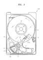
- FIG. 3 is a plan view of an HDD 100 according to an embodiment of the present invention
- FIGS. 4 and 5 are a perspective view and a plan view showing a closeup of an HSA 110A according to an embodiment of the present invention
- FIG. 6 is a perspective view showing a closeup of an HSA 110B according to another embodiment of the present invention
- FIG. 7 is a perspective view showing a closeup of an HSA 110C according to another embodiment of the present invention.
- the HDD 100 includes a spindle motor 105, a disk 107 that is a data storage medium, and the HSA 110A in a housing including a base member 101 and a cover member (not shown) assembled with the base member 101.
- the spindle motor 105 rotates the disk 107 at a high speed and is fixed to the base member 101.
- the disk 107 is assembled with the spindle motor 105 and rotates at a high speed in the direction of the arrow.
- the high-speed rotation induces an air flow in the same direction as the arrow on the surface of the disk 107.
- the HSA 110A includes a head slider 130 in which is embedded a magnetic head (not shown) for writing or reading data.
- the head slider 130 moves to a specific track of the disk 107 and reads or writes data from or to the disk 107.
- the HSA 110A includes a swing arm 113 rotatably assembled with the base member 101 by a pivot bearing 111, a connection plate 117A assembled with an edge part of the swing arm 113, a suspension 120 attached to the connection plate 117A, and the head slider 130 attached to an edge part of the suspension 120.
- the HSA 110A also includes an overmold 134, which is assembled with the swing arm 113 and includes a wound voice coil 135.
- a magnet 137 and a yoke 138 supporting the magnet 137 are respectively located above and below the overmold 134.
- the magnet 137, the yoke 138, and the voice coil 135 of the HSA 110A form a voice coil motor and provide a driving force for rotating the HSA 110A.
- the head slider 130 When the air flow induced by the high-speed rotation of the disk 107 passes between the disk 107 and the head slider 130, lift is exerted on the head slider 130.
- the head slider 130 floats at a height at which the lift balances the elastic pressure of the suspension 120, which presses the head slider 130 towards the disk 107. While floating, the magnetic head embedded in the head slider 130 reads and writes data from and to the disk 107.
- the HDD 100 also includes a flexible printed circuit (FPC) 145, which electrically connects the HSA 110A to a main printed circuit board (PCB (not shown)) below the base member 101, and a ramp 140 for parking the HSA 110A when the HDD 100 stops operating.
- FPC flexible printed circuit
- PCB main printed circuit board
- a ramp 140 for parking the HSA 110A when the HDD 100 stops operating.
- the HSA 110A rotates clockwise so that the head slider 130 moves away from the disk 107, and an end-tap 124 placed in an edge part of the suspension 120 slides along the slope of the ramp 140, to safely place the HSA 110A in a safety zone. That is, the HSA 110A maintains a fixed state without rotating, regardless of disturbance.
- connection plate 117A of the HSA 110A connects the edge part of the swing arm 113 to the suspension 120.
- the edge part of the swing arm 113 is assembled with the connection plate 117A by swaging.
- the edge part of the swing arm 113 and the connection plate 117A respectively include swaging holes 114A and 118A for the swaging assembly.
- the suspension 120 includes a load beam 121, which is attached to the connection plate 117A and elastically biases the head slider 130 towards the surface of the disk 107, and a flexure 129, which is attached to the load beam 121 and supports the head slider 130 on the surface of the HSA 110A which faces the disk.
- the end-tap 124 is placed in an edge part of the load beam 121, and side-rails 122 are formed in the both sides of the load beam 121 to maintain the stiffness of the load beam 121.
- the load beam 121 includes a pair of combination parts 126 and 127 attached to the connection plate 117A.
- the first combination part 126 is attached to a corner 119a of the connection plate 117A, which is closer to the center of the disk 107, and the second combination part 127 is attached to another corner 119b of the connection plate 117A which is further from the center of the disk 107. That is, as illustrated in FIG. 4, the first combination part 126 is attached to the connection plate 117A in a position which is lower than that of the second combination part 127 by a predetermined height difference F1.
- the height difference F1 is equal to or less than the thickness of the connection plate 117A, and may be between 0 and 0.5 mm.
- the HSA 110B further includes a spacer 132 located between the first combination part 126 and the lower surface of the connection plate 117A, in order to create a height difference F2 between the first combination part 126 and the second combination part 127.
- the spacer 132 is attached to the lower surface of the corner 119a of the connection plate 117A
- the first combination part 126 is attached to the lower surface of the spacer 132
- the second combination part 127 is attached to the lower surface of the other corner 119b of the connection plate 117A, resulting in the height difference F2.
- other embodiments of the present invention include creating a height difference between the pair of combination parts 126 and 127 of the suspension 120 attached to the upper surface of the connection plate 117A by placing the spacer 132 between the second combination part 127 and the connection plate 117A, and an HSA having an additional combination part between the first combination part 126 and the second combination part 127.
- connection plate 117A is attached to the edge part of the swing arm 113 to be biased towards the center of the disk 107.
- an imaginary line which passes through the rotation center of the swing arm 113, i.e. the center of the pivot bearing 111, and the center of the edge part of the swing arm 113 is a center line L1 of the swing arm 113
- an imaginary line which is the axis of symmetry of the suspension 120 and extends along the length of the suspension 120 is a center line L2 of the suspension 120
- the center line L2 of the suspension 120 is parallel to the center line L1 of the swing arm 113 but separated by a gap G1 towards the center of the disk 107.
- the gap G1 may be 0 to 2 mm in order to maintain the bonding force between the connection plate 117A and the edge part of the swing arm 113.
- the centers of the swaging holes 114A and 118A formed in the swing arm 113 and the connection plate 117A are located on the center line L2 of the suspension 120, not on the center line L1 of the swing arm 113, so that the connection plate 117A can be assembled with the edge part of the swing arm 113 and biased towards the center of the disk 107.
- a connection plate 117B having a width W2 greater than the width W1 of the edge part of the swing arm 113 is assembled with the edge part of the swing arm 113, and the suspension 120 is attached to an edge part of the connection plate 117B and biased towards the center of the disk 107.
- the center line L2 of the suspension 120 is parallel to the center line L1 of the swing arm 113 but separated by a gap G2 towards the center of the disk 107.
- connection plate 117B is assembled with the edge part of the swing arm 113 and not biased towards either side of the edge part of the swing arm 113.
- the centers of swaging holes 114B and 118B formed in the swing arm 113 and the connection plate 117B are located on the center line L1 of the swing arm 113.
- FIG. 8 is a graph illustrating the correlation between frequency of vibration applied to an HDD and the amount of off-track according to an embodiment of the present invention
- FIG. 9 is a schematic diagram for describing an effect of reducing off-track due to disk vibration in an HSA according to an embodiment of the present invention
- FIG. 10 is a schematic diagram for describing an effect of reducing the off-track due to arm bending in an HSA according to an embodiment of the present invention.
- the inventor analyzed the amount of off-track at various frequencies using a computer simulation of an HSA (referring to FIGS. 3 through 5) having both a first characteristic, in which the first combination part 126 is attached to the connection plate 117A in a lower position than the second combination part 127, and a second characteristic, in which the connection plate 117A is assembled with the swing arm 113 so as to be biased towards the center of the disk 107 (hereinafter, a first type HSA); an HSA having only the first characteristic (hereinafter, a second type HSA); and a conventional HSA having neither the first characteristic nor the second characteristic (hereinafter, a third type HSA).
- a first type HSA an HSA having only the first characteristic
- a second type HSA HSA having only the first characteristic
- a conventional HSA having neither the first characteristic nor the second characteristic
- peaks formed in an A1 zone indicate the occurrence of the off-track due to disk vibration
- a peak formed in an A2 zone indicates the occurrence of the off-track due to arm bending.
- Table 1 shows an analysis result of FIG. 8. [Table 1] Amount of off-track due to disk vibration [ ⁇ 10 -6 mm] Amount of off-track due to arm bending [ ⁇ 10 -6 mm] First type HSA 12.80 1.69 Second type HSA 12.47 3.09 Third type HSA 44.29
- the first and second type HSAs having the first characteristic have 1/4 the amount of off-track due to disk vibration than the third type HSA.
- the first type HSA having both the first characteristic and the second characteristic has 1/2 the amount of off-track due to arm bending than the second type HSA.
- the first type HSA or the second type HSA having the first characteristic since distortion of a suspension (referring to reference numeral 120 of FIG. 3) is induced when the HSA vibrates up and down, if the disk moves downwards, a magnetic head embedded in a head slider of the HSA moves to the rotation center of the HSA and is biased towards the outer circumference of the disk (from h1(d0) or h2(d0) to h1(d1) or h2(d1)), and if the disk moves upwards, the magnetic head moves in the opposite direction (from h1(d0) or h2(d0) to h1(d2) or h2(d2)).
- the distance between the magnetic head and the track i.e.
- a magnetic head moves towards the outer circumference of a disk (from h2(a0) to h2(a1)) due to distortion of the suspension caused by the first characteristic, and if arm bending in which the edge part of the swing arm bends downwards occurs in the second type HSA, the magnetic head moves towards the center of the disk (from h2(a0) to h2(a2)).
- the distance between the magnetic head and a track i.e. between h2(a1) and T or h2(a2) and T is further, resulting in off-track due to arm bending.
- the second characteristic compensates for the motion of a magnetic head towards the outer circumference of a disk caused by the first characteristic.
- the magnetic head of the first type HSA deviates from the track T by a smaller amount when the arm bending occurs (from h1(a0) to h1(a1) or from h1(a0) to h1(a2)).
- the distance between the magnetic head of the first type HSA and the track i.e. between h1(a1) and T or h1(a2) and T
- the second type HSA i.e. between h2(a1) and T or h2(a2) and T.
Landscapes
- Supporting Of Heads In Record-Carrier Devices (AREA)
- Moving Of Heads (AREA)
Applications Claiming Priority (1)
| Application Number | Priority Date | Filing Date | Title |
|---|---|---|---|
| KR1020060065869A KR100723533B1 (ko) | 2006-07-13 | 2006-07-13 | Hsa 및 이를 구비한 하드디스크 드라이브 |
Publications (3)
| Publication Number | Publication Date |
|---|---|
| EP1879183A2 true EP1879183A2 (fr) | 2008-01-16 |
| EP1879183A3 EP1879183A3 (fr) | 2008-12-24 |
| EP1879183B1 EP1879183B1 (fr) | 2010-02-24 |
Family
ID=38278770
Family Applications (1)
| Application Number | Title | Priority Date | Filing Date |
|---|---|---|---|
| EP07111913A Expired - Fee Related EP1879183B1 (fr) | 2006-07-13 | 2007-07-06 | Ensemble de têtes de lecteur et disque dur équipé d'un tel ensemble |
Country Status (6)
| Country | Link |
|---|---|
| US (1) | US7889459B2 (fr) |
| EP (1) | EP1879183B1 (fr) |
| JP (1) | JP4881236B2 (fr) |
| KR (1) | KR100723533B1 (fr) |
| CN (1) | CN101105947B (fr) |
| DE (1) | DE602007004907D1 (fr) |
Cited By (1)
| Publication number | Priority date | Publication date | Assignee | Title |
|---|---|---|---|---|
| EP2246847A3 (fr) * | 2009-04-28 | 2011-01-05 | Samsung Electronics Co., Ltd. | Support de tête de lecture, disque dur équipé d'un tel support et son procédé de fabrication |
Families Citing this family (8)
| Publication number | Priority date | Publication date | Assignee | Title |
|---|---|---|---|---|
| JP4703734B2 (ja) * | 2009-01-22 | 2011-06-15 | サンコール株式会社 | 磁気ヘッドサスペンション |
| US8094414B1 (en) * | 2009-07-09 | 2012-01-10 | Western Digital Technologies, Inc. | Head gimbal assembly mounting mechanism |
| KR101579318B1 (ko) * | 2010-04-29 | 2015-12-21 | 엘지전자 주식회사 | 태양 전지 및 그 제조 방법 |
| US8339747B1 (en) | 2011-03-11 | 2012-12-25 | Western Digital Technologies, Inc. | Removable actuator assemblies for testing head gimbal assemblies of a storage device |
| US8705209B2 (en) | 2011-10-14 | 2014-04-22 | Western Digital Technologies, Inc. | Suspension clamp for clamping a disk drive suspension to an actuator arm |
| US8830632B1 (en) | 2013-03-04 | 2014-09-09 | Seagate Technology Llc | Gimbal assembly resonance mode anti-biasing |
| JP6275658B2 (ja) * | 2015-02-18 | 2018-02-07 | 日東電工株式会社 | 回路付サスペンション基板 |
| US9502057B1 (en) * | 2015-06-30 | 2016-11-22 | Magnecomp Corporation | Disk drive suspension having offset swage hub hole |
Citations (3)
| Publication number | Priority date | Publication date | Assignee | Title |
|---|---|---|---|---|
| US20020131211A1 (en) | 2001-03-19 | 2002-09-19 | Nhk Spring Co., Ltd. | Suspension for disc drive |
| US6920018B2 (en) | 2003-07-10 | 2005-07-19 | Samsung Electronics, Co., Ltd. | Method and apparatus reducing off-track head motion due to disk vibration in a disk drive through flexure mounting and/or non-symmetric hinging within the head gimbal assembly |
| US6958879B2 (en) | 2003-07-10 | 2005-10-25 | Samsung Electronics Co., Ltd. | Method and apparatus reducing off track head motion due to disk vibration in a hard disk drive using configuration of the disk drive servo controller |
Family Cites Families (16)
| Publication number | Priority date | Publication date | Assignee | Title |
|---|---|---|---|---|
| JPH03130970A (ja) | 1989-10-16 | 1991-06-04 | Fujitsu Ltd | 磁気ディスク装置のキャリッジ |
| JP2577240Y2 (ja) * | 1991-10-30 | 1998-07-23 | 富士電気化学株式会社 | 磁気ヘッド用の取付アーム |
| JP3240935B2 (ja) * | 1996-09-20 | 2001-12-25 | 株式会社日立製作所 | 磁気ディスク装置 |
| US6154952A (en) * | 1998-04-22 | 2000-12-05 | Hutchinson Technology, Inc. | Attachment isolation structures for adjusting head slider static attitude |
| US6233124B1 (en) | 1998-11-18 | 2001-05-15 | Seagate Technology Llc | Piezoelectric microactuator suspension assembly with improved stroke length |
| US6144532A (en) * | 1999-03-25 | 2000-11-07 | Magnecomp Corporation | Suspension with readily manufacturable vertically and laterally offset lifter |
| SG92724A1 (en) * | 2000-07-24 | 2002-11-19 | Inst Data Storage | Head suspension assembly with piezoelectric beam micro actuator |
| JP2002056515A (ja) | 2000-08-09 | 2002-02-22 | Tdk Corp | 磁気ヘッド装置及び該磁気ヘッド装置を備えた磁気ディスク装置 |
| JP2003151232A (ja) | 2001-11-08 | 2003-05-23 | Nhk Spring Co Ltd | ディスクドライブ用サスペンション |
| US6914752B2 (en) * | 2003-03-26 | 2005-07-05 | Hitachi Global Storage Technologies Netherlands B.V. | Magnetic recording disk drive with continuous contact air-bearing slider |
| US7136260B2 (en) * | 2003-07-10 | 2006-11-14 | Samsung Electronics Co., Ltd. | Method and apparatus reducing off track head motion due to disk vibration in a hard disk drive through the head gimbal assembly |
| JP2005093002A (ja) * | 2003-09-18 | 2005-04-07 | Hitachi Global Storage Technologies Netherlands Bv | 回転円板形記憶装置 |
| US7280316B1 (en) * | 2003-09-19 | 2007-10-09 | Magnecomp Corporation | Hard disk drive suspension employing a vertical offset to reduce track mis-registration induced by disk vibration |
| KR100532496B1 (ko) * | 2004-01-19 | 2005-11-30 | 삼성전자주식회사 | 플렉셔 리미터를 가진 서스펜션 조립체와 이를 채용한디스크 드라이브용 액츄에이터 |
| KR100721301B1 (ko) * | 2005-02-18 | 2007-05-28 | 후지쯔 가부시끼가이샤 | 자기 헤드용 액츄에이터 및 자기 디스크 장치 |
| US7606000B1 (en) * | 2005-05-03 | 2009-10-20 | Hutchinson Technology Incorporated | Offset structure for disk drive head suspension |
-
2006
- 2006-07-13 KR KR1020060065869A patent/KR100723533B1/ko not_active Expired - Fee Related
-
2007
- 2007-06-28 JP JP2007171038A patent/JP4881236B2/ja not_active Expired - Fee Related
- 2007-07-06 EP EP07111913A patent/EP1879183B1/fr not_active Expired - Fee Related
- 2007-07-06 DE DE602007004907T patent/DE602007004907D1/de active Active
- 2007-07-11 CN CN2007101291108A patent/CN101105947B/zh not_active Expired - Fee Related
- 2007-07-12 US US11/776,630 patent/US7889459B2/en not_active Expired - Fee Related
Patent Citations (3)
| Publication number | Priority date | Publication date | Assignee | Title |
|---|---|---|---|---|
| US20020131211A1 (en) | 2001-03-19 | 2002-09-19 | Nhk Spring Co., Ltd. | Suspension for disc drive |
| US6920018B2 (en) | 2003-07-10 | 2005-07-19 | Samsung Electronics, Co., Ltd. | Method and apparatus reducing off-track head motion due to disk vibration in a disk drive through flexure mounting and/or non-symmetric hinging within the head gimbal assembly |
| US6958879B2 (en) | 2003-07-10 | 2005-10-25 | Samsung Electronics Co., Ltd. | Method and apparatus reducing off track head motion due to disk vibration in a hard disk drive using configuration of the disk drive servo controller |
Cited By (2)
| Publication number | Priority date | Publication date | Assignee | Title |
|---|---|---|---|---|
| EP2246847A3 (fr) * | 2009-04-28 | 2011-01-05 | Samsung Electronics Co., Ltd. | Support de tête de lecture, disque dur équipé d'un tel support et son procédé de fabrication |
| US8400737B2 (en) | 2009-04-28 | 2013-03-19 | Seagate Technology Llc | Support structure with enhanced vibrational response |
Also Published As
| Publication number | Publication date |
|---|---|
| CN101105947A (zh) | 2008-01-16 |
| KR100723533B1 (ko) | 2007-05-30 |
| EP1879183B1 (fr) | 2010-02-24 |
| JP2008021402A (ja) | 2008-01-31 |
| EP1879183A3 (fr) | 2008-12-24 |
| CN101105947B (zh) | 2011-04-13 |
| US20080013205A1 (en) | 2008-01-17 |
| JP4881236B2 (ja) | 2012-02-22 |
| US7889459B2 (en) | 2011-02-15 |
| DE602007004907D1 (de) | 2010-04-08 |
Similar Documents
| Publication | Publication Date | Title |
|---|---|---|
| EP1879183B1 (fr) | Ensemble de têtes de lecteur et disque dur équipé d'un tel ensemble | |
| US6965500B1 (en) | Suspension design for attenuation of disk flutter induced track mis-registration of a hard disk drive by manipulation of load beam pitch angle | |
| US8432641B1 (en) | Disk drive with multi-zone arm damper | |
| US7113371B1 (en) | Suspension design for attenuation of disk flutter induced track mis-registration of a hard disk drive by manipulation of the hinge and/or load beam | |
| US8345387B1 (en) | Disk drive with transverse plane damper | |
| US8570682B2 (en) | Disk drive using an airflow reduction plate and methods of manufacturing thereof | |
| EP1884927A2 (fr) | Ensemble de cardan de tête et lecteur de disque dur doté de celui-ci | |
| JP4881241B2 (ja) | ヘッドスタックアセンブリおよびハードディスクドライブ | |
| JP2008287769A (ja) | ディスク装置 | |
| US8009390B2 (en) | Head gimbal assembly with recessed portion and manufacturing method thereof | |
| EP1522065B1 (fr) | Mecanisme de support de tete, dispositif d'entrainement de tete et disque | |
| US8400737B2 (en) | Support structure with enhanced vibrational response | |
| US7626811B2 (en) | Low profile disk drive unit | |
| US7355817B2 (en) | Head suspension assembly with femto-slider and disk device provided with the same | |
| KR20100118332A (ko) | Hsa, 상기 hsa를 구비한 하드디스크 드라이브, 및 상기 하드디스크 드라이브의 오프트랙 저감 방법 | |
| US8259418B2 (en) | Head suspension assembly and disk device with the same | |
| EP2031585A1 (fr) | Plaque à bras, ensemble d'empilement de tête la comprenant et disque dur comprenant l'ensemble d'empilement de tête | |
| JP3788865B2 (ja) | 磁気ディスク装置 | |
| US20070291415A1 (en) | Head stack assembly and hard disk drive including the head stack assembly | |
| KR100761826B1 (ko) | 회전날개 및 이를 구비한 하드디스크 드라이브 | |
| US20250364007A1 (en) | Disk device and head gimbal assembly | |
| US20060181810A1 (en) | Flexure leg optimization shapes for lateral stiffness | |
| US20080186631A1 (en) | Head stack assembly and hard disk drive apparatus with the same |
Legal Events
| Date | Code | Title | Description |
|---|---|---|---|
| PUAI | Public reference made under article 153(3) epc to a published international application that has entered the european phase |
Free format text: ORIGINAL CODE: 0009012 |
|
| 17P | Request for examination filed |
Effective date: 20070706 |
|
| AK | Designated contracting states |
Kind code of ref document: A2 Designated state(s): AT BE BG CH CY CZ DE DK EE ES FI FR GB GR HU IE IS IT LI LT LU LV MC MT NL PL PT RO SE SI SK TR |
|
| AX | Request for extension of the european patent |
Extension state: AL BA HR MK YU |
|
| PUAL | Search report despatched |
Free format text: ORIGINAL CODE: 0009013 |
|
| AK | Designated contracting states |
Kind code of ref document: A3 Designated state(s): AT BE BG CH CY CZ DE DK EE ES FI FR GB GR HU IE IS IT LI LT LU LV MC MT NL PL PT RO SE SI SK TR |
|
| AX | Request for extension of the european patent |
Extension state: AL BA HR MK RS |
|
| 17Q | First examination report despatched |
Effective date: 20090316 |
|
| AKX | Designation fees paid |
Designated state(s): DE |
|
| GRAP | Despatch of communication of intention to grant a patent |
Free format text: ORIGINAL CODE: EPIDOSNIGR1 |
|
| GRAS | Grant fee paid |
Free format text: ORIGINAL CODE: EPIDOSNIGR3 |
|
| GRAA | (expected) grant |
Free format text: ORIGINAL CODE: 0009210 |
|
| AK | Designated contracting states |
Kind code of ref document: B1 Designated state(s): DE |
|
| REF | Corresponds to: |
Ref document number: 602007004907 Country of ref document: DE Date of ref document: 20100408 Kind code of ref document: P |
|
| PLBE | No opposition filed within time limit |
Free format text: ORIGINAL CODE: 0009261 |
|
| STAA | Information on the status of an ep patent application or granted ep patent |
Free format text: STATUS: NO OPPOSITION FILED WITHIN TIME LIMIT |
|
| 26N | No opposition filed |
Effective date: 20101125 |
|
| PGFP | Annual fee paid to national office [announced via postgrant information from national office to epo] |
Ref country code: DE Payment date: 20130729 Year of fee payment: 7 |
|
| REG | Reference to a national code |
Ref country code: DE Ref legal event code: R119 Ref document number: 602007004907 Country of ref document: DE |
|
| PG25 | Lapsed in a contracting state [announced via postgrant information from national office to epo] |
Ref country code: DE Free format text: LAPSE BECAUSE OF NON-PAYMENT OF DUE FEES Effective date: 20150203 |
|
| REG | Reference to a national code |
Ref country code: DE Ref legal event code: R119 Ref document number: 602007004907 Country of ref document: DE Effective date: 20150203 |