EP1879258A2 - Elektrische Verbindungsvorrichtung, Herstellungsverfahren dafür, elektrische Leitung und Solarmodulanordnung mit einer solchen Verbindungsvorrichtung - Google Patents
Elektrische Verbindungsvorrichtung, Herstellungsverfahren dafür, elektrische Leitung und Solarmodulanordnung mit einer solchen Verbindungsvorrichtung Download PDFInfo
- Publication number
- EP1879258A2 EP1879258A2 EP07012300A EP07012300A EP1879258A2 EP 1879258 A2 EP1879258 A2 EP 1879258A2 EP 07012300 A EP07012300 A EP 07012300A EP 07012300 A EP07012300 A EP 07012300A EP 1879258 A2 EP1879258 A2 EP 1879258A2
- Authority
- EP
- European Patent Office
- Prior art keywords
- electrical
- housing
- connecting device
- contact element
- electrical conductor
- Prior art date
- Legal status (The legal status is an assumption and is not a legal conclusion. Google has not performed a legal analysis and makes no representation as to the accuracy of the status listed.)
- Granted
Links
Images




Classifications
-
- H—ELECTRICITY
- H01—ELECTRIC ELEMENTS
- H01R—ELECTRICALLY-CONDUCTIVE CONNECTIONS; STRUCTURAL ASSOCIATIONS OF A PLURALITY OF MUTUALLY-INSULATED ELECTRICAL CONNECTING ELEMENTS; COUPLING DEVICES; CURRENT COLLECTORS
- H01R11/00—Individual connecting elements providing two or more spaced connecting locations for conductive members which are, or may be, thereby interconnected, e.g. end pieces for wires or cables supported by the wire or cable and having means for facilitating electrical connection to some other wire, terminal, or conductive member, blocks of binding posts
- H01R11/11—End pieces or tapping pieces for wires, supported by the wire and for facilitating electrical connection to some other wire, terminal or conductive member
-
- H—ELECTRICITY
- H01—ELECTRIC ELEMENTS
- H01R—ELECTRICALLY-CONDUCTIVE CONNECTIONS; STRUCTURAL ASSOCIATIONS OF A PLURALITY OF MUTUALLY-INSULATED ELECTRICAL CONNECTING ELEMENTS; COUPLING DEVICES; CURRENT COLLECTORS
- H01R25/00—Coupling parts adapted for simultaneous co-operation with two or more identical counterparts, e.g. for distributing energy to two or more circuits
- H01R25/003—Coupling parts adapted for simultaneous co-operation with two or more identical counterparts, e.g. for distributing energy to two or more circuits the coupling part being secured only to wires or cables
-
- H—ELECTRICITY
- H01—ELECTRIC ELEMENTS
- H01R—ELECTRICALLY-CONDUCTIVE CONNECTIONS; STRUCTURAL ASSOCIATIONS OF A PLURALITY OF MUTUALLY-INSULATED ELECTRICAL CONNECTING ELEMENTS; COUPLING DEVICES; CURRENT COLLECTORS
- H01R4/00—Electrically-conductive connections between two or more conductive members in direct contact, i.e. touching one another; Means for effecting or maintaining such contact; Electrically-conductive connections having two or more spaced connecting locations for conductors and using contact members penetrating insulation
- H01R4/24—Connections using contact members penetrating or cutting insulation or cable strands
- H01R4/2404—Connections using contact members penetrating or cutting insulation or cable strands the contact members having teeth, prongs, pins or needles penetrating the insulation
- H01R4/2406—Connections using contact members penetrating or cutting insulation or cable strands the contact members having teeth, prongs, pins or needles penetrating the insulation having needles or pins
-
- H—ELECTRICITY
- H01—ELECTRIC ELEMENTS
- H01R—ELECTRICALLY-CONDUCTIVE CONNECTIONS; STRUCTURAL ASSOCIATIONS OF A PLURALITY OF MUTUALLY-INSULATED ELECTRICAL CONNECTING ELEMENTS; COUPLING DEVICES; CURRENT COLLECTORS
- H01R13/00—Details of coupling devices of the kinds covered by groups H01R12/70 or H01R24/00 - H01R33/00
- H01R13/46—Bases; Cases
- H01R13/502—Bases; Cases composed of different pieces
- H01R13/504—Bases; Cases composed of different pieces different pieces being moulded, cemented, welded, e.g. ultrasonic welding, or swaged together
Definitions
- the present invention relates to an electrical connecting device with a housing and with a contact element, which, on the one hand, is seated in a receiving opening of the housing and, on the other hand, contacts an electrical conductor, and a method for producing an electrical connecting device of this type. Furthermore, the present invention relates to an electrical line with at least one electrical conductor and with an electrical connecting device of this type. Furthermore, the invention relates to a solar module, which is connected to at least one electrical connecting device of this type, and a solar module arrangement with a plurality of solar modules, which are connected in each case to a electrical connecting device of this type.
- a solar module for producing electrical energy typically comprises a layer arrangement, for example a planar-like front glass covering and a rear glass covering, with the formation of an intermediate space between the two glass layers.
- the individual solar cells which contribute to the production of electrical energy by a photovoltaic effect, are arranged between these layers and are connected to one another within the layer arrangement by an electrical connection system.
- Solar panels of this type in which solar cells are arranged under a glass covering, are electrically interconnected at points which are exposed with respect to the solar radiation. For ease of assembly and maintenance, it is favorable if special plug connections provided for this are used for the electrical interconnection.
- plug connections for solar modules at their conventional site of use, for example on the roof of a house, are exposed to weather and environmental influences such as snow, rain, frost or insolation and have to withstand these influences for years.
- weather and environmental influences such as snow, rain, frost or insolation
- mechanical stresses in the assembly and maintenance or mechanical stresses as a result of environmental influences such as, for example, mechanical tensile stresses.
- plug connections are also required for the electrical connection of the solar panels, the individual plug connections do not only have to be robust and reliable, but also economical.
- the present invention is based on the object of disclosing an electrical connecting device of the type mentioned at the outset, which is suitable for comparatively rapid and simple assembly, in particular of a solar panel, and which can also be produced comparatively economically.
- a corresponding method for producing an electrical connecting device of this type is to be disclosed.
- an electrical connecting device according to claim 1 and by a method for producing a electrical connecting device of this type according to claim 21.
- the present invention also relates to an electrical line with at least one electrical connecting device of this type according to claim 15.
- the invention relates to a solar module according to claim 18, which is connected to a electrical connecting device of this type, and a solar module arrangement according to claim 19 with a plurality of solar modules, which are connected in each case to a electrical connecting device of this type.
- the electrical connecting device has a housing and a contact element, a first portion of the contact element being seated in a receiving opening of the housing, a second portion of the contact element projecting into a receiving channel of the housing, which is configured to receive at least one elongate electrical conductor, and the second portion of the contact element is configured to contact the electrical conductor.
- the elongate electrical conductor is received in the receiving channel of the housing and is contacted by the contact element.
- At least one part of the housing and at least one part of the contacted electrical conductor are surrounded by a common sheath of non-conductive material with the formation of a uniform bond.
- the electrical conductor is firstly arranged in the receiving channel of the housing.
- the electrical conductor is then contacted by the contact element in the second portion of the contact element.
- At least one part of the housing and at least one part of the contacted electrical conductor are then surrounded by the common sheath made of non-conductive material.
- the invention offers the advantage, in this case, that an electrical connecting device of this type can be produced comparatively economically.
- a contacting device of this type allows a comparatively rapid and simple assembly in particular of solar modules in a relatively high number, it being possible to connect these solar modules, for example via a corresponding counter-contact element, to the contact element of the electrical connecting device, the elongate electrical conductor in this case being, for example, part of a feed or return line of the solar module(s).
- a rapid and simple assembly can be achieved, in particular, when the electrical connecting devices are already provided on the corresponding electrical line and are already delivered in the corresponding assembled state on the electrical line, so the construction staff, to assemble the solar modules, only have to connect the corresponding counter-contact element to the contact element of a electrical connecting device on the electrical line.
- a better allocation of the connections on the solar module to the corresponding electrical connecting devices on the electrical line can thereby be achieved. It is advantageous compared to the previous procedure in particular, according to which each solar panel connection is connected individually or a solar panel arrangement is connected in distributor boxes specially provided for this in a collective manner.
- the cable connectors to be provided can be reduced according to the concept of the present invention in that an electrical line is used to connect solar modules and is matched with respect to the number of electrical connecting devices arranged thereon to the number of solar modules to be connected.
- At least one part of the housing and at least one part of the contacted electrical conductor is injection molded around with a common plastics material to form the sheath.
- the common sheath can thus be created in a particularly effective manner from non-conductive material with the formation of a uniform bond for the electrical connecting device.
- the second portion of the contact element is configured in such a way that, for contacting, it can penetrate into an insulated electrical conductor, in particular it can pierce the latter.
- the contact element is configured as what is known as a piercing contact, which can penetrate into an insulated electrical conductor to contact it.
- the contact element is, in this context, preferably configured as a contact pin, the second portion being configured to contact the electrical conductor as a contact tip.
- the elongate electrical conductor is, in particular, arranged in a substantially U-shaped receiving channel, in other words, the receiving channel of the housing has a substantially U-shaped cross-section, in which the contacted electrical conductor comes to rest.
- the housing can thus be placed in a simple manner on the electrical conductor, it being possible for a contact element configured as a contact pin to pierce the electrical conductor with this movement.
- the elongate electrical conductor in particular an electrical cable, can be contacted by the contact element of the electrical connecting device by simply placing on the housing of the electrical connecting device.
- the contact element has a third portion opposing the second portion, which third portion is oriented in the housing to contact a counter-contact element.
- a electrical connecting device contacted by an electrical conductor can easily be contacted by a counter-contact element to produce, for example, a contact to a solar module.
- This is advantageous, in particular, when the third portion of the contact element, together with at least one part of the housing of the electrical connecting device, is configured as a plug connection for contacting the counter-contact element.
- the plug connection is preferably provided with at least one polarizing element which cooperates with a corresponding polarizing element of the counter-contact element.
- the polarizing element is configured in the form of polarizing ribs, which cooperate with corresponding polarizing ribs of the counter-contact element. This can easily prevent a connection cable of the solar module with positive polarity being connected via the electrical connecting device to a supply line with negative polarity.
- the housing is configured with two different portions, a first portion having the receiving channel.
- This first portion of the housing is provided with a smaller diameter than a second portion of the housing, so a step-shaped offset is produced, for example, between the first portion and the second portion of the housing.
- This is advantageous, in particular, when only the first portion of the housing is to be injection molded around with the common sheath, so the surface then produced of the injection-molded material can equate to the diameter of the second portion. It can therefore be advantageously ensured that a substantially identically shaped surface of the electrical connecting device is produced.
- the second portion of the housing is configured, in particular, in such a way that its outer surface substantially borders, in a flush manner, the outer surface of the common sheath made of non-conductive material, which surrounds the first portion of the housing.
- At least one clamping element is provided, which is attached to the contacted electrical conductor and is surrounded by the common sheath made of non-conductive material.
- a clamping element of this type is preferably attached to the electrical conductor before the at least one part of the housing and the at least one part of the contacted electrical conductor are surrounded and is then surrounded by the common sheath, in particular injection molded around.
- the clamping element preferably has a material composition such that the clamping element can connect to the non-conductive material of the sheath so a tight bond in total can form around the electrical conductor, which in particular ensures a longitudinal water tightness of the electrical connecting device and can also contribute to a tensile stress relief of the contact point.
- the concept of the present invention offers, in particular, the far-reaching advantages when, after production, the electrical connecting device is assembled on an electrical line and is injection molded around portions thereof, so, as the end result, an electrical line with at least one electrical connecting device is obtained, in which the electrical conductor of the electrical line is already contacted by the contact element of the electrical connecting device.
- a plurality of electrical connecting devices is preferably arranged spaced apart from one another along the electrical line, in particular in the manner of what is known as a daisy chain. This means that the individual electrical connecting devices are connected to one another in series along the electrical line via the electrical conductor.
- An electrical line configured in this manner is, for example, what is known as an endless line which can be correspondingly cut to length at the assembly site.
- An electrical line of this type is preferably configured, together with the electrical connecting devices, in such a way that the electrical line together with the electrical connecting devices can be wound onto a cable drum.
- an electrical supply line for a solar panel arrangement can be delivered with pre-assembled electrical connecting devices, so the assembly staff can produce the respective electrical connection between the electrical line and the respective solar panel merely via a corresponding counter-contact element.
- This may be provided in the form of a simple plug connection with which a comparatively rapid and simple assembly of the electrical connection system can be achieved.
- the electrical connecting device according to the present invention and the electrical line, which is provided with at least one such electrical connecting device can be variously used in many various ways. Although the present invention is described against the background of the electrical connection of solar modules, it is in no way limited thereto. Rather, use of an electrical connecting device according to the invention is also conceivable in all other applications in which an electrical connection to an elongate electrical conductor is to be produced to connect, in particular, an electrical device of any type to the elongate electrical conductor, for example an electrical cable.
- An electrical connecting device according to the invention may also provide a plurality of contact elements to, for example, contact a multi-pole electrical cable.
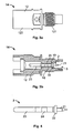
- Fig. 1 shows a side view (Fig. 1a) and a sectional view (Fig. 1b) of an embodiment of a negative coded connector housing 11 of an electrical connecting device according to the invention.
- the housing 11 has a first portion 111 and a second portion 112, the first portion 111 of the housing 11 having a smaller external diameter than the second portion 112.
- the housing 11 is provided in the first portion 111 with an external thread, which, however, has no important significance for the function of the present invention.
- the housing 11 is a connector housing, which is manufactured with an available tool which is also used to produce other connector housings. To simplify the manufacturing sequences, the tool is also adjusted in this case such that the external thread is also provided in the housing 11, although it is not of important significance for the present invention.
- a contact element 2 is provided in the housing 11, a first portion 24 of the contact element 2 being seated in a receiving opening 18 of the housing 11, so that the contact element 2 is fixed in this first portion 24 in the housing 11 in a radial direction.
- the contact element 2 has a stop 22, which corresponds with a counter-stop 19 in the receiving opening 18 of the housing 11. To assemble the contact element 2, the contact element 2 is pressed into the housing 11 to the stop 22, so that the stop 22 rests on the counter-stop 19 so the contact element 2 is fixed in an axial direction.
- a second portion 21 of the contact element 2 projects into a receiving channel 3 of the housing 11, which is configured to receive at least one elongate electrical conductor.
- the receiving channel 3 of the housing has a substantially U-shaped cross-section, in which the elongate electrical conductor, for example in the form of an electrical cable, comes to rest.
- the second portion 21 of the contact element 2 projects into the receiving channel 3 to contact the electrical conductor in the receiving channel.
- the second portion 21 of the contact element 2 is preferably configured in such a way that it is suitable for contacting an insulated electrical conductor, in other words in particular, can penetrate such a conductor or pierce it.
- the contact element 2 is configured, in particular, as a contact pin, the second portion 21 being formed as a contact tip to penetrate an insulation of an electrical conductor and to pierce the electrical conductor itself.
- the contact element 2 is therefore configured as what is known as a piercing contact.
- a third portion 23 of the contact element 2 opposing the second portion 21 is oriented in the housing 11 to contact a counter-contact element, which is not shown in the present figures for the sake of simplicity.
- the third portion 23 of the contact element 2 together with a part of the housing 11, is configured as a plug connection 13 for contacting the counter-contact element.
- Fig. 2 shows a plug face side view of the housing 11 according to Fig. 1a with the visible plug connection 13 for connection to a counter-contact element. It can be seen, in particular from Fig. 2, that the plug connection 13 has two polarizing elements in the form of polarizing ribs 15, which cooperate with corresponding polarizing ribs of the counter-contact element. This ensures that, in the housing 11, only a plug provided for this purpose with the counter-contact element can pierce the plug connection 13.
- Fig. 3 shows a side view (Fig. 3a) and a sectional view (Fig. 3b) of a positive coded connector housing 12, which is substantially constructed identical to the previously described negative coded connector housing 11.
- the housing 12 also has a first portion 121 and a second portion 122, which have varying external diameters.
- the plug connection 14, compared to the plug connection 13, has varying polarizing ribs, as shown, for example, in the plan view of the housing 12 according to Fig. 5b.
- the corresponding counter-contact element is connected to the negative coded connector housing 11 instead of to the positive coded connector housing 12.
- the respective polarizing ribs do not correspond with one another, so the counter-contact element cannot be inserted into the plug connection.
- the arrangement of the housing 12 equates to the arrangement of the housing 11 according to Fig. 1.
- Fig. 4 in this context, shows a larger side view of the contact element 2 according to an embodiment of the invention, which is configured as a contact pin.
- the contact element 2 is suitable as a piercing contact, in that the contact tip is configured in such a way that it can pierce an insulated electrical conductor in order to contact it.
- the stop 22 is used for axially fixing the contact element 2 in the respective housing 11, 12.
- the first portion 24 comes to rest in the receiving opening of the housing 11, 12 and the third portion 23 is used for contacting a counter-contact element.
- FIG. 5 An intermediate stage of a electrical connecting device according to the invention during the production of the electrical connecting device is shown in Fig. 5.
- the elongate electrical conductor 5 is arranged in the form of an electrical cable in the receiving channel 3 of the housing 12 in such a way that the contact pin 2 has penetrated the insulation of the electrical conductor 5 and contacts the inner electrical conductor.
- This is achieved by placing the housing 12, as explained with the aid of Fig. 3 on the electrical conductor 5, the housing 12 being pressed down onto the electrical conductor 5, so the stop 22 of the contact element 2 rests on the counter-stop 19 of the housing 12.
- the U-shaped receiving channel 3 is substantially matched to a diameter of the electrical conductor 5.
- FIG. 7 in this context shows an embodiment of a clamping element 4, which comprises a plurality of parts, only the upper portion 41 of the clamping element 4 being shown in Fig. 7.
- the clamping element 4 has ribs 42 for pressing into the cable jacket of the electrical conductor 5 and a latching connection 43, which latches with a corresponding latching connection on a lower portion (not shown) of the clamping element 4.
- the lower portion of the clamping element 4 is identical in configuration to the upper portion 41, the latching connection of the lower portion latching with the corresponding latching connection 44 of the upper portion 41.
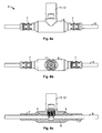
- Fig. 6 shows views of a completed electrical connecting device 1 according to the embodiment of the present invention.
- the basic principle of the arrangement of the electrical connecting device 1 on the electrical conductor 5 is independent here of whether a positive coded connector housing 12 or a negative coded connector housing 11 is used. Therefore, the housing 11, 12 of the electrical connecting device 11 may be both a positive coded connector housing 12 or a negative coded connector housing 11.
- the plan view of Fig. 6b is shown using the example of a negative coded connector housing 11.
- the first portion 111 of the housing 11 or the first portion 121 of the housing 12 are injection molded around with a plastics material, so this first portion 111, 121 of the housing 11, 12 and a corresponding portion of the contacted electrical conductor 5 are surrounded by a common sheath 6 made of non-conductive plastics material with the formation of a uniform bond.
- the housing 11, 12 is fastened, fixed and stabilized by the sheath 6 on the electrical conductor 5.
- the respective second portion 112 of the housing 11 or the second portion 122 of the housing 12 is configured in such a way that an outer surface thereof substantially borders an outer surface of the sheath 6 made of non-conductive plastics material in a flush manner. This is shown in more detail, in particular with the aid of the sectional view of Fig.
- the clamping elements 4 are also surrounded by the sheath 6, and kink protection elements 7 are configured on end portions of the sheath 6 for the contacted electrical conductor 5, so the electrical conductor 5 cannot kink at the two points on either side, at which the sheath 6 ends.
- the kink protection elements 7 are formed in a manner known per se, as shown in Figs. 6a and 6b.
- TPE thermoplastic elastomer
- the housings 11, 12 and clamping elements 4 preferably contain polycarbonate (PC) or are manufactured therefrom which can also be processed by the injection molding method.
- PC polycarbonate
- the combination of the materials TPE and PC for the production of the electrical connecting device 1 according to the invention, has the particular advantage that TPE adheres comparatively well to PC. Thus, a good connection can be provided between the TPE material of the sheath 6 and the PC material of the clamping elements 4 or the housing 11, 12.
- this has the advantage that a comparatively good water tightness can be produced against the penetration of longitudinal water along the electrical conductor 5; for, on the one hand, the cable jacket of the electrical conductor 5 is slightly pressed in by the clamping elements 4 so that water tightness can be produced at this point and, on the other hand, the adhesion between PC and TPE contributes to the fact that good water tightness is also produced between the sheath 6 and the clamping elements 4. This applies equally to the connection between the housing 11, 12 and the sheath 6. A substantially tight electrical connecting device 1 is thus produced, irrespective of the material of the electrical conductor 5 used.
- clamping elements 4 are used for mechanical tensile stress relief of the contacting point, at which the contact element 2 pierces the electrical conductor 5, it being possible to achieve a load distribution over the clamping elements 4 and the sheath 6 comparatively uniformly at a plurality of points.
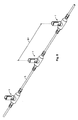
- Fig. 8 shows a perspective view of an embodiment of an electrical line having at least an electrical conductor 5 according to the invention, in which an exemplary number of electrical connecting devices 1 according to the invention is provided.
- a plurality of electrical connecting devices 1 in the form of what are known as T-connectors are arranged along the electrical conductor 5, in particular in the manner of a daisy chain, as it is known.
- the electrical connecting devices 1, for example, have a regular spacing B1.
- the electrical conductor 5 may, for example, be an endless manufactured cable, which can be wound together with the electrical connecting devices 1 onto a cable drum.
- the electrical conductor 5 can then be cut to length into corresponding portions at the assembly site so an electrical conductor 5 with electrical connecting devices 1 already provided thereon is available at the assembly site. After laying the electrical conductor 5, a corresponding counter-contact element only has to be introduced into the electrical connecting device 1, as described more thoroughly above. A comparatively rapid and simple assembly can thus be achieved when connecting the electrical device 1 to the electrical conductor 5.
- Fig. 9 shows a schematic view of an exemplary solar module arrangement 300 and of electrical connection lines having at least one electrical conductor 501, 502 connected thereto with electrical connecting devices 101, 102 according to the invention.
- the solar module arrangement 300 has a plurality of solar modules 31 to 34, which are connected to an external electrical connection system.
- the solar modules 31 to 34 in each case have electrical connections 36, which are configured in the present embodiment as connection boxes, which for example, are connected to the rear glass covering of the solar module 31 to 34.
- the respective solar modules 31 to 34 are connected via solar connection cables 37 and 38 to the electrical conductors 501 or the electrical conductors 502.
- the electrical conductor 501 has negative coded electrical connecting devices 101, while the electrical conductor 502 has positive coded electrical connecting devices 102, according to the structure as described above.
- the electrical connecting devices 101, 102 are arranged on the respective electrical conductors 501 or 502 at a spacing B1 (Fig. 8), which corresponds with the length or width of the solar modules 31 to 34, so the electrical conductors 501, 502 provide in each case at least one electrical devices 101, 102 at each of the solar modules 31 to 34.
- the spacing B1 of the electrical connecting devices 101, 102 preferably amounts to the center distance B2 between two of the solar modules 31 to 34. This has the advantage that an easy allocation can be produced between the electrical connecting devices 101, 102 and the respective solar module 31 to 34.
- the electrical conductors 501 and 502 can be laid at the assembly site of the solar modules 31 to 34, it being possible to easily connect the solar modules 31 to 34 to the electrical conductors 501 and 502 by closing the respective plug connection at the respective electrical devices 101, 102.
Landscapes
- Connector Housings Or Holding Contact Members (AREA)
- Connections By Means Of Piercing Elements, Nuts, Or Screws (AREA)
- Details Of Connecting Devices For Male And Female Coupling (AREA)
- Manufacturing Of Electrical Connectors (AREA)
- Photovoltaic Devices (AREA)
- Insulated Conductors (AREA)
- Multi-Conductor Connections (AREA)
Applications Claiming Priority (1)
| Application Number | Priority Date | Filing Date | Title |
|---|---|---|---|
| DE102006032275A DE102006032275B3 (de) | 2006-07-12 | 2006-07-12 | Elektrische Verbindungsvorrichtung und Verfahren zu seiner Herstellung sowie elektrische Leitung und Solarmodulanordnung mit einer solchen Verbindungsvorrichtung |
Publications (3)
| Publication Number | Publication Date |
|---|---|
| EP1879258A2 true EP1879258A2 (de) | 2008-01-16 |
| EP1879258A3 EP1879258A3 (de) | 2008-06-04 |
| EP1879258B1 EP1879258B1 (de) | 2011-08-10 |
Family
ID=38606444
Family Applications (1)
| Application Number | Title | Priority Date | Filing Date |
|---|---|---|---|
| EP07012300A Active EP1879258B1 (de) | 2006-07-12 | 2007-06-22 | Elektrische Verbindungsvorrichtung, Herstellungsverfahren dafür, elektrische Leitung und Solarmodulanordnung mit einer solchen Verbindungsvorrichtung |
Country Status (6)
| Country | Link |
|---|---|
| US (1) | US7445488B2 (de) |
| EP (1) | EP1879258B1 (de) |
| JP (1) | JP5008191B2 (de) |
| CN (1) | CN101106224B (de) |
| DE (1) | DE102006032275B3 (de) |
| ES (1) | ES2369560T3 (de) |
Cited By (2)
| Publication number | Priority date | Publication date | Assignee | Title |
|---|---|---|---|---|
| EP2424050A1 (de) * | 2010-08-30 | 2012-02-29 | Albert Stekelenburg | Außenmehrfachsteckdose |
| BE1019885A3 (nl) * | 2011-03-18 | 2013-02-05 | Isophi Bvba | Toestellen voor de controle van accu's. |
Families Citing this family (18)
| Publication number | Priority date | Publication date | Assignee | Title |
|---|---|---|---|---|
| US20080271774A1 (en) | 2007-05-01 | 2008-11-06 | Kalkanoglu Husnu M | Photovoltaic Roofing Wiring Array, Photovoltaic Roofing Wiring System and Roofs Using Them |
| DE102007036998A1 (de) | 2007-08-06 | 2009-02-19 | Fraunhofer-Gesellschaft zur Förderung der angewandten Forschung e.V. | Verfahren zur Herstellung von amorphen metallorganischen Makromolekülen, mit diesem Verfahren erhaltenes Material und seine Verwendung |
| JP5538698B2 (ja) * | 2008-05-15 | 2014-07-02 | 株式会社カネカ | 太陽電池モジュールの敷設構造 |
| EP2322738A4 (de) | 2008-09-10 | 2015-09-02 | Kaneka Corp | Solarzellenmodul und solarzellenarray |
| US20100093206A1 (en) * | 2008-10-15 | 2010-04-15 | Checkson Die Casting And Product Factory Limited | Electrical connector for electrical communication between a power cable and an electrical device |
| US8368405B2 (en) * | 2009-07-30 | 2013-02-05 | Thomas & Betts International, Inc. | Remote test point for electrical connector |
| US8656657B2 (en) | 2009-08-31 | 2014-02-25 | Certainteed Corporation | Photovoltaic roofing elements |
| US8572836B2 (en) * | 2010-04-19 | 2013-11-05 | Sunpower Corporation | Method of manufacturing a large-area segmented photovoltaic module |
| CN102118000B (zh) * | 2010-11-09 | 2012-11-28 | 常熟市福莱德连接器科技有限公司 | 光伏连接器的制作方法 |
| EP2456010A1 (de) * | 2010-11-23 | 2012-05-23 | Saia-Burgess Controls AG | Netzwerkkomponente mit einer elektrischen Vorrichtung |
| CN102904131B (zh) * | 2011-07-29 | 2014-12-17 | 江苏德威木业有限公司 | 电热地板的供电插座和供电线路 |
| US8641431B2 (en) * | 2012-02-17 | 2014-02-04 | Tyco Electronics Corporation | Coaxial cable connector |
| JP6050196B2 (ja) * | 2013-08-09 | 2016-12-21 | 株式会社オートネットワーク技術研究所 | ワイヤハーネス及びコネクタ |
| US10992254B2 (en) | 2014-09-09 | 2021-04-27 | Shoals Technologies Group, Llc | Lead assembly for connecting solar panel arrays to inverter |
| KR20170011614A (ko) * | 2015-07-23 | 2017-02-02 | 엘지전자 주식회사 | 태양광 모듈 및 이를 구비한 태양광 시스템 |
| DE102020107396A1 (de) * | 2020-03-18 | 2021-09-23 | Harting Electric Gmbh & Co. Kg | Modulares Hochstromsteckverbindersystem |
| DE102023108857B3 (de) | 2023-04-06 | 2024-08-08 | HIK GmbH | Verfahren zur Herstellung einer elektrischen Kabelverbindungsanordnung |
| JP2025006456A (ja) * | 2023-06-29 | 2025-01-17 | ウシオ電機株式会社 | 給受電用ソケットおよび給受電装置 |
Citations (2)
| Publication number | Priority date | Publication date | Assignee | Title |
|---|---|---|---|---|
| GB2010027A (en) | 1977-12-13 | 1979-06-20 | Chloride Group Ltd | Electrical testing point |
| EP0698947A2 (de) | 1994-08-25 | 1996-02-28 | The Whitaker Corporation | Elektrisches Kabelbaum mit elektrischem Verbinder mit elektrischem Bauteil darin und dessen Herstellungsverfahren |
Family Cites Families (11)
| Publication number | Priority date | Publication date | Assignee | Title |
|---|---|---|---|---|
| US4798544A (en) * | 1986-01-06 | 1989-01-17 | Minnesota Mining And Manufacturing Company | Low profile clip connector with integral contact support insert |
| FR2759499B1 (fr) * | 1997-02-10 | 1999-03-12 | Schneider Electric Sa | Dispositif de connexion et connecteur a perforation d'isolant susceptible d'incorporer un tel dispositif |
| DE29721354U1 (de) * | 1997-12-03 | 1998-02-12 | Weidmüller Interface GmbH & Co, 32760 Detmold | Steckverbinder für elektrische Leiter |
| DE20008163U1 (de) * | 2000-05-05 | 2000-09-07 | Alcatel, Paris | Anschlußsystem für mehrere elektrische Bauteile |
| JP2002124694A (ja) * | 2000-10-18 | 2002-04-26 | Mitsubishi Heavy Ind Ltd | 太陽光発電システム及びその配線接続方法 |
| JP2004014920A (ja) * | 2002-06-10 | 2004-01-15 | Sumitomo Wiring Syst Ltd | ケーブル連結部構造 |
| DE10251287A1 (de) * | 2002-11-04 | 2004-05-19 | Tyco Electronics Amp Gmbh | Verbindungsanordnung |
| CN2634674Y (zh) * | 2003-01-30 | 2004-08-18 | 上海行田电产有限公司 | 防水连接器 |
| DE10305381A1 (de) * | 2003-02-10 | 2004-08-19 | Tyco Electronics Amp Gmbh | Verbindungsanordnung und Herstellverfahren für eine Verbindungsanordnung |
| JP4124750B2 (ja) * | 2004-03-11 | 2008-07-23 | 行田電線株式会社 | 医用差込プラグ |
| JP2005293991A (ja) * | 2004-03-31 | 2005-10-20 | Fujikura Ltd | フラットハーネス |
-
2006
- 2006-07-12 DE DE102006032275A patent/DE102006032275B3/de not_active Expired - Fee Related
-
2007
- 2007-06-22 ES ES07012300T patent/ES2369560T3/es active Active
- 2007-06-22 EP EP07012300A patent/EP1879258B1/de active Active
- 2007-06-28 US US11/770,103 patent/US7445488B2/en not_active Expired - Fee Related
- 2007-07-12 JP JP2007183050A patent/JP5008191B2/ja not_active Expired - Fee Related
- 2007-07-12 CN CN2007101287507A patent/CN101106224B/zh not_active Expired - Fee Related
Patent Citations (2)
| Publication number | Priority date | Publication date | Assignee | Title |
|---|---|---|---|---|
| GB2010027A (en) | 1977-12-13 | 1979-06-20 | Chloride Group Ltd | Electrical testing point |
| EP0698947A2 (de) | 1994-08-25 | 1996-02-28 | The Whitaker Corporation | Elektrisches Kabelbaum mit elektrischem Verbinder mit elektrischem Bauteil darin und dessen Herstellungsverfahren |
Cited By (2)
| Publication number | Priority date | Publication date | Assignee | Title |
|---|---|---|---|---|
| EP2424050A1 (de) * | 2010-08-30 | 2012-02-29 | Albert Stekelenburg | Außenmehrfachsteckdose |
| BE1019885A3 (nl) * | 2011-03-18 | 2013-02-05 | Isophi Bvba | Toestellen voor de controle van accu's. |
Also Published As
| Publication number | Publication date |
|---|---|
| CN101106224A (zh) | 2008-01-16 |
| JP2008021654A (ja) | 2008-01-31 |
| EP1879258A3 (de) | 2008-06-04 |
| CN101106224B (zh) | 2012-05-30 |
| JP5008191B2 (ja) | 2012-08-22 |
| US20080014784A1 (en) | 2008-01-17 |
| DE102006032275B3 (de) | 2008-01-03 |
| EP1879258B1 (de) | 2011-08-10 |
| US7445488B2 (en) | 2008-11-04 |
| ES2369560T3 (es) | 2011-12-01 |
Similar Documents
| Publication | Publication Date | Title |
|---|---|---|
| EP1879258B1 (de) | Elektrische Verbindungsvorrichtung, Herstellungsverfahren dafür, elektrische Leitung und Solarmodulanordnung mit einer solchen Verbindungsvorrichtung | |
| US8007306B2 (en) | Electrical connection system | |
| US20110011642A1 (en) | Low leakage electrical joints and wire harnesses, and method of making the same | |
| CN101944663B (zh) | 支承和偏置内接点的绝缘子 | |
| US4089576A (en) | Insulated connection of photovoltaic devices | |
| US20060283628A1 (en) | Connecting Device for Connecting Electrical Foil Conductors | |
| WO2007079584A3 (en) | Photovoltaic solar roof tile assembly system | |
| US7744395B1 (en) | Quick-disconnect waterproof connector | |
| WO2008014502A3 (en) | Electrical connector for conductive wires encapsulated in protective tubing | |
| CN101169992B (zh) | 同轴扁平缆线及其制造方法 | |
| CN2634674Y (zh) | 防水连接器 | |
| WO2009078414A1 (ja) | 防水機能をもつコネクタ付電線束 | |
| EP3776843B1 (de) | Dacheindeckungselement, solar-dacheindeckungselement, anordnung von solar-dacheindeckungselementen und herstellungsverfahren für ein solar-dacheindeckungselement | |
| CA2891846C (en) | Photovoltaic tile | |
| US10192706B2 (en) | Undermolded and overmolded fuse joints | |
| JP4080663B2 (ja) | ケーブル分岐部のモールド方法 | |
| JP2939740B1 (ja) | コネクタとその水密方法 | |
| US20050252674A1 (en) | Electrical junction | |
| US5669786A (en) | Electrical terminal for high current applications | |
| GB2442173A (en) | Mineral insulated electric cable termination | |
| CN2896582Y (zh) | 软尾导电连接装置 | |
| US20020019164A1 (en) | Electrical connector, especially for use in the sensor field | |
| KR20080005236A (ko) | 커넥터 하우징 조립체 및 와이어를 호일내의 전도성 리드에접속시키는 커넥터 접촉부를 내장하는 방법 | |
| CN110854792A (zh) | 室内布线单元电缆 | |
| JPH0660967U (ja) | 電気絶縁キャップ |
Legal Events
| Date | Code | Title | Description |
|---|---|---|---|
| PUAI | Public reference made under article 153(3) epc to a published international application that has entered the european phase |
Free format text: ORIGINAL CODE: 0009012 |
|
| AK | Designated contracting states |
Kind code of ref document: A2 Designated state(s): AT BE BG CH CY CZ DE DK EE ES FI FR GB GR HU IE IS IT LI LT LU LV MC MT NL PL PT RO SE SI SK TR |
|
| AX | Request for extension of the european patent |
Extension state: AL BA HR MK YU |
|
| PUAL | Search report despatched |
Free format text: ORIGINAL CODE: 0009013 |
|
| AK | Designated contracting states |
Kind code of ref document: A3 Designated state(s): AT BE BG CH CY CZ DE DK EE ES FI FR GB GR HU IE IS IT LI LT LU LV MC MT NL PL PT RO SE SI SK TR |
|
| AX | Request for extension of the european patent |
Extension state: AL BA HR MK RS |
|
| 17P | Request for examination filed |
Effective date: 20081119 |
|
| AKX | Designation fees paid |
Designated state(s): DE ES FR IT NL |
|
| 17Q | First examination report despatched |
Effective date: 20100813 |
|
| GRAP | Despatch of communication of intention to grant a patent |
Free format text: ORIGINAL CODE: EPIDOSNIGR1 |
|
| GRAS | Grant fee paid |
Free format text: ORIGINAL CODE: EPIDOSNIGR3 |
|
| GRAA | (expected) grant |
Free format text: ORIGINAL CODE: 0009210 |
|
| AK | Designated contracting states |
Kind code of ref document: B1 Designated state(s): DE ES FR IT NL |
|
| REG | Reference to a national code |
Ref country code: DE Ref legal event code: R096 Ref document number: 602007016356 Country of ref document: DE Effective date: 20111013 |
|
| REG | Reference to a national code |
Ref country code: ES Ref legal event code: FG2A Ref document number: 2369560 Country of ref document: ES Kind code of ref document: T3 Effective date: 20111201 |
|
| REG | Reference to a national code |
Ref country code: NL Ref legal event code: VDEP Effective date: 20110810 |
|
| PG25 | Lapsed in a contracting state [announced via postgrant information from national office to epo] |
Ref country code: NL Free format text: LAPSE BECAUSE OF FAILURE TO SUBMIT A TRANSLATION OF THE DESCRIPTION OR TO PAY THE FEE WITHIN THE PRESCRIBED TIME-LIMIT Effective date: 20110810 |
|
| PLBE | No opposition filed within time limit |
Free format text: ORIGINAL CODE: 0009261 |
|
| STAA | Information on the status of an ep patent application or granted ep patent |
Free format text: STATUS: NO OPPOSITION FILED WITHIN TIME LIMIT |
|
| 26N | No opposition filed |
Effective date: 20120511 |
|
| REG | Reference to a national code |
Ref country code: DE Ref legal event code: R097 Ref document number: 602007016356 Country of ref document: DE Effective date: 20120511 |
|
| REG | Reference to a national code |
Ref country code: FR Ref legal event code: PLFP Year of fee payment: 9 |
|
| REG | Reference to a national code |
Ref country code: DE Ref legal event code: R081 Ref document number: 602007016356 Country of ref document: DE Owner name: TE CONNECTIVITY GERMANY GMBH, DE Free format text: FORMER OWNER: TYCO ELECTRONICS AMP GMBH, 64625 BENSHEIM, DE |
|
| REG | Reference to a national code |
Ref country code: FR Ref legal event code: CD Owner name: TE CONNECTIVITY GERMANY GMBH Effective date: 20151027 |
|
| REG | Reference to a national code |
Ref country code: FR Ref legal event code: PLFP Year of fee payment: 10 |
|
| PGFP | Annual fee paid to national office [announced via postgrant information from national office to epo] |
Ref country code: ES Payment date: 20160627 Year of fee payment: 10 |
|
| PGFP | Annual fee paid to national office [announced via postgrant information from national office to epo] |
Ref country code: IT Payment date: 20160627 Year of fee payment: 10 |
|
| REG | Reference to a national code |
Ref country code: FR Ref legal event code: PLFP Year of fee payment: 11 |
|
| REG | Reference to a national code |
Ref country code: FR Ref legal event code: PLFP Year of fee payment: 12 |
|
| PG25 | Lapsed in a contracting state [announced via postgrant information from national office to epo] |
Ref country code: IT Free format text: LAPSE BECAUSE OF NON-PAYMENT OF DUE FEES Effective date: 20170622 |
|
| REG | Reference to a national code |
Ref country code: ES Ref legal event code: FD2A Effective date: 20181114 |
|
| PG25 | Lapsed in a contracting state [announced via postgrant information from national office to epo] |
Ref country code: ES Free format text: LAPSE BECAUSE OF NON-PAYMENT OF DUE FEES Effective date: 20170623 |
|
| PGFP | Annual fee paid to national office [announced via postgrant information from national office to epo] |
Ref country code: DE Payment date: 20250402 Year of fee payment: 19 |
|
| PGFP | Annual fee paid to national office [announced via postgrant information from national office to epo] |
Ref country code: FR Payment date: 20250508 Year of fee payment: 19 |