EP1879729B1 - Horizontaltischpresse mit elektromechanischem antrieb für das spritzgiessen von thermoplasten - Google Patents
Horizontaltischpresse mit elektromechanischem antrieb für das spritzgiessen von thermoplasten Download PDFInfo
- Publication number
- EP1879729B1 EP1879729B1 EP05750306A EP05750306A EP1879729B1 EP 1879729 B1 EP1879729 B1 EP 1879729B1 EP 05750306 A EP05750306 A EP 05750306A EP 05750306 A EP05750306 A EP 05750306A EP 1879729 B1 EP1879729 B1 EP 1879729B1
- Authority
- EP
- European Patent Office
- Prior art keywords
- motor
- rotation
- shaft
- plunger
- mold
- Prior art date
- Legal status (The legal status is an assumption and is not a legal conclusion. Google has not performed a legal analysis and makes no representation as to the accuracy of the status listed.)
- Expired - Lifetime
Links
- 238000001746 injection moulding Methods 0.000 title claims abstract description 7
- 229920001169 thermoplastic Polymers 0.000 title 1
- 239000004416 thermosoftening plastic Substances 0.000 title 1
- 238000002347 injection Methods 0.000 claims abstract description 19
- 239000007924 injection Substances 0.000 claims abstract description 19
- 230000008878 coupling Effects 0.000 claims abstract description 3
- 238000010168 coupling process Methods 0.000 claims abstract description 3
- 238000005859 coupling reaction Methods 0.000 claims abstract description 3
- 230000002459 sustained effect Effects 0.000 claims abstract description 3
- 239000012815 thermoplastic material Substances 0.000 claims description 13
- 230000033001 locomotion Effects 0.000 claims description 10
- 239000012530 fluid Substances 0.000 claims description 4
- 230000005540 biological transmission Effects 0.000 abstract description 5
- 229940064639 minipress Drugs 0.000 description 5
- WFXFYZULCQKPIP-UHFFFAOYSA-N prazosin hydrochloride Chemical compound [H+].[Cl-].N=1C(N)=C2C=C(OC)C(OC)=CC2=NC=1N(CC1)CCN1C(=O)C1=CC=CO1 WFXFYZULCQKPIP-UHFFFAOYSA-N 0.000 description 5
- 239000000463 material Substances 0.000 description 4
- 230000008901 benefit Effects 0.000 description 3
- 238000012423 maintenance Methods 0.000 description 3
- 239000000243 solution Substances 0.000 description 2
- 230000009466 transformation Effects 0.000 description 2
- 238000009966 trimming Methods 0.000 description 2
- 239000002699 waste material Substances 0.000 description 2
- 230000009471 action Effects 0.000 description 1
- 238000004140 cleaning Methods 0.000 description 1
- 230000001351 cycling effect Effects 0.000 description 1
- 230000002708 enhancing effect Effects 0.000 description 1
- 230000005484 gravity Effects 0.000 description 1
- 238000009434 installation Methods 0.000 description 1
- 230000009347 mechanical transmission Effects 0.000 description 1
- 210000000056 organ Anatomy 0.000 description 1
- 230000008520 organization Effects 0.000 description 1
- 239000004033 plastic Substances 0.000 description 1
- 230000009467 reduction Effects 0.000 description 1
- 125000006850 spacer group Chemical group 0.000 description 1
- 239000010891 toxic waste Substances 0.000 description 1
Images


Classifications
-
- B—PERFORMING OPERATIONS; TRANSPORTING
- B29—WORKING OF PLASTICS; WORKING OF SUBSTANCES IN A PLASTIC STATE IN GENERAL
- B29C—SHAPING OR JOINING OF PLASTICS; SHAPING OF MATERIAL IN A PLASTIC STATE, NOT OTHERWISE PROVIDED FOR; AFTER-TREATMENT OF THE SHAPED PRODUCTS, e.g. REPAIRING
- B29C45/00—Injection moulding, i.e. forcing the required volume of moulding material through a nozzle into a closed mould; Apparatus therefor
- B29C45/03—Injection moulding apparatus
-
- B—PERFORMING OPERATIONS; TRANSPORTING
- B29—WORKING OF PLASTICS; WORKING OF SUBSTANCES IN A PLASTIC STATE IN GENERAL
- B29C—SHAPING OR JOINING OF PLASTICS; SHAPING OF MATERIAL IN A PLASTIC STATE, NOT OTHERWISE PROVIDED FOR; AFTER-TREATMENT OF THE SHAPED PRODUCTS, e.g. REPAIRING
- B29C45/00—Injection moulding, i.e. forcing the required volume of moulding material through a nozzle into a closed mould; Apparatus therefor
- B29C45/17—Component parts, details or accessories; Auxiliary operations
- B29C45/40—Removing or ejecting moulded articles
- B29C45/4005—Ejector constructions; Ejector operating mechanisms
-
- B—PERFORMING OPERATIONS; TRANSPORTING
- B29—WORKING OF PLASTICS; WORKING OF SUBSTANCES IN A PLASTIC STATE IN GENERAL
- B29C—SHAPING OR JOINING OF PLASTICS; SHAPING OF MATERIAL IN A PLASTIC STATE, NOT OTHERWISE PROVIDED FOR; AFTER-TREATMENT OF THE SHAPED PRODUCTS, e.g. REPAIRING
- B29C45/00—Injection moulding, i.e. forcing the required volume of moulding material through a nozzle into a closed mould; Apparatus therefor
- B29C45/17—Component parts, details or accessories; Auxiliary operations
- B29C45/46—Means for plasticising or homogenising the moulding material or forcing it into the mould
- B29C45/47—Means for plasticising or homogenising the moulding material or forcing it into the mould using screws
- B29C45/50—Axially movable screw
- B29C45/5008—Drive means therefor
-
- B—PERFORMING OPERATIONS; TRANSPORTING
- B29—WORKING OF PLASTICS; WORKING OF SUBSTANCES IN A PLASTIC STATE IN GENERAL
- B29C—SHAPING OR JOINING OF PLASTICS; SHAPING OF MATERIAL IN A PLASTIC STATE, NOT OTHERWISE PROVIDED FOR; AFTER-TREATMENT OF THE SHAPED PRODUCTS, e.g. REPAIRING
- B29C45/00—Injection moulding, i.e. forcing the required volume of moulding material through a nozzle into a closed mould; Apparatus therefor
- B29C45/17—Component parts, details or accessories; Auxiliary operations
- B29C45/64—Mould opening, closing or clamping devices
- B29C45/66—Mould opening, closing or clamping devices mechanical
-
- B—PERFORMING OPERATIONS; TRANSPORTING
- B29—WORKING OF PLASTICS; WORKING OF SUBSTANCES IN A PLASTIC STATE IN GENERAL
- B29C—SHAPING OR JOINING OF PLASTICS; SHAPING OF MATERIAL IN A PLASTIC STATE, NOT OTHERWISE PROVIDED FOR; AFTER-TREATMENT OF THE SHAPED PRODUCTS, e.g. REPAIRING
- B29C45/00—Injection moulding, i.e. forcing the required volume of moulding material through a nozzle into a closed mould; Apparatus therefor
- B29C45/17—Component parts, details or accessories; Auxiliary operations
- B29C2045/1784—Component parts, details or accessories not otherwise provided for; Auxiliary operations not otherwise provided for
- B29C2045/1792—Machine parts driven by an electric motor, e.g. electric servomotor
- B29C2045/1794—Machine parts driven by an electric motor, e.g. electric servomotor by a rotor or directly coupled electric motor, e.g. using a tubular shaft motor
-
- B—PERFORMING OPERATIONS; TRANSPORTING
- B29—WORKING OF PLASTICS; WORKING OF SUBSTANCES IN A PLASTIC STATE IN GENERAL
- B29C—SHAPING OR JOINING OF PLASTICS; SHAPING OF MATERIAL IN A PLASTIC STATE, NOT OTHERWISE PROVIDED FOR; AFTER-TREATMENT OF THE SHAPED PRODUCTS, e.g. REPAIRING
- B29C45/00—Injection moulding, i.e. forcing the required volume of moulding material through a nozzle into a closed mould; Apparatus therefor
- B29C45/17—Component parts, details or accessories; Auxiliary operations
- B29C45/40—Removing or ejecting moulded articles
- B29C45/4005—Ejector constructions; Ejector operating mechanisms
- B29C2045/4036—Ejector constructions; Ejector operating mechanisms driven by a screw and nut mechanism
-
- B—PERFORMING OPERATIONS; TRANSPORTING
- B29—WORKING OF PLASTICS; WORKING OF SUBSTANCES IN A PLASTIC STATE IN GENERAL
- B29C—SHAPING OR JOINING OF PLASTICS; SHAPING OF MATERIAL IN A PLASTIC STATE, NOT OTHERWISE PROVIDED FOR; AFTER-TREATMENT OF THE SHAPED PRODUCTS, e.g. REPAIRING
- B29C45/00—Injection moulding, i.e. forcing the required volume of moulding material through a nozzle into a closed mould; Apparatus therefor
- B29C45/17—Component parts, details or accessories; Auxiliary operations
- B29C45/46—Means for plasticising or homogenising the moulding material or forcing it into the mould
- B29C45/47—Means for plasticising or homogenising the moulding material or forcing it into the mould using screws
- B29C45/50—Axially movable screw
- B29C45/5008—Drive means therefor
- B29C2045/5056—Drive means therefor screws axially driven by a rotatable screw shaft cooperating with a fixed nut
-
- B—PERFORMING OPERATIONS; TRANSPORTING
- B29—WORKING OF PLASTICS; WORKING OF SUBSTANCES IN A PLASTIC STATE IN GENERAL
- B29C—SHAPING OR JOINING OF PLASTICS; SHAPING OF MATERIAL IN A PLASTIC STATE, NOT OTHERWISE PROVIDED FOR; AFTER-TREATMENT OF THE SHAPED PRODUCTS, e.g. REPAIRING
- B29C45/00—Injection moulding, i.e. forcing the required volume of moulding material through a nozzle into a closed mould; Apparatus therefor
- B29C45/17—Component parts, details or accessories; Auxiliary operations
- B29C45/46—Means for plasticising or homogenising the moulding material or forcing it into the mould
- B29C45/47—Means for plasticising or homogenising the moulding material or forcing it into the mould using screws
- B29C45/50—Axially movable screw
- B29C45/5008—Drive means therefor
- B29C2045/5076—Drive means therefor using a single drive motor for rotary and for axial movements of the screw
Definitions
- the present invention relates in general to presses for injection molding of thermoplastic materials and in particular to relatively small presses (mini-presses) of small size and weight capable of exerting a closing force generally up to about 10 tons.
- Mini-presses are commonly employed in laboratories for developing and prototyping injection moldable objects of thermoplastic materials and/or for producing pieces of relatively small size.
- weight and encumbrance represent two aspects of fundamental importance, in consideration of the use to which they are destined and to the environment in which they are often deployed.
- mini-presses In order to reduce encumbrance and weight, commercially available mini-presses employ hydraulic or pneumatic circuits for actuating the operating movements of the press. In case of hydraulic transmissions, hydraulic pumps driven by electric motors are used.
- the objective of the present applicants was to devise a horizontal bench press with electro-mechanical drive system, free of any hydraulic transmission, that would not be penalized in terms of weight and encumbrance, compared to an additional horizontal bench press with hydraulic drive system for injection molding of thermoplastic materials.
- the novel technical solutions of the peculiar horizontal bench press architecture of the present applicants achieve an outstanding containment of encumbrances and weights that permit to realize a bench mini-press, capable of a closing force of up to 7 times, having extremely reduced dimensions (140 x 50 x 60 cm) and a total weight lower than 200 Kg.
- the mini-press with fully electromechanical drive system of the present applicants has dimensions and weight that preferably compared to that of a common hydraulic mini-press of the same capabilities.
- the use circulating balls screw device ensure in addition a remarkably higher precision in positioning of movement axis compared to the precision levels that can be obtained by common hydraulic transmissions.
- productivity is enhanced by the fact that the distinct electric motors ensure a complete overlapping of movements without any loss of power, besides other productivity enhancing features that will be described in the following description of a practical embodiment of the novel mini-press.
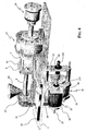
- the stress structure of the press comprises an horizontal bench 1, to be placed on a suitable support of table (not shown in the figures).
- a robust platen 2 is fixed vertically onto the horizontal bench and is mechanically tied by four horizontal parallel guide rods 10 to the casing of the motor 17 that is also solidly fastened onto the bench 1.
- the vertical platen 2 has a recess 3 in which a first half mold having a conical seat suitable to sealingly receive the conical nozzle 6 of a injection cylinder 5, passing through a hole 4 of the plate 2 and inside which a plunger 13, commonly having a screw-like shape, axe.
- the mobile platen 7 of the press is slightly sustained by the horizontal guide bars and has a recess 8 in which the other half mold is mounted.
- the opening and closing of the mold is actuated by the motor 17, the tubular shaft of which onto which the rotor of the motor is mounted, includes the lead nut portion of a circulating ball worm gear 15, the worm portion of which is formed over a tubular shaft 9, the outer cylindrical surface of which has longitudinal splines and the one end mechanically connected to the mobile platen 7 of the press.
- Rotation of the rotor of the motor 17 produces advancement or retraction of the splined tubular shaft 9, depending on the commanded direction of rotation of the motor 17, thus causing and opening the mold.
- tubular shaft 9 for the opening and closing of the mold extends for a certain distance out of the other side of the casing of the motor 17 for sustaining at its free end a second motor 16, the function of which is to expel the molded piece from the half mold carried by the mobile platen 7 of the press in the recess 8, once the mold has been opened.
- the molded piece expulsion action from the mold is performed by the expulsion road 11 passing inside the tubular shaft 9 of opening and closing of the mold.
- the tubular shaft on which the rotor of the motor 16 is mounted comprises the lead nut portion of a circulating ball worm gear 14, that engages onto a threaded portion of the road 11, which may therefore be advanced in order to expel the molded piece from the cavity of the half mold carried by the mobile platen 2 of the press and retracted to its stand-by position, by commanding rotation of the motor 16 in one and in the opposite direction, respectively.
- the co-axiality of movement of the mold closing and opening shaft 9 and of the molded piece expulsion road 11, and of the respective worm gears of transformation rotational/linear of the motion (circulating ball worm gears 14 and 15) used by the respective motors 16 and 17, permits to sustain the actuating device of expulsion of the molded piece in a cantilever fashion at the end of the tubular shaft 9 and closing and opening of the mold. This minimizes encumbrance and weights avoiding the need of realizing distinct structures specifically dedicated to implement a molded piece expulsion function from the half mold carried in the recess 8 of the mobile platen 7 of the press.
- the press employs an injection device having an helicoidal shaped plunger 13 acting inside the injection cylinder 5, the conical outlet of which is pushed to sealingly abut against a conical seat of the inlet port of the half mold mounted inside the recess 3 of the fixed platen 2 of the press, passing through a hole 4 of the platen.
- the helicoidal plunger 13 "draws" a predetermined volume of fluidified thermoplastic material in front of its end, by backing and rotating it, such to leave behind a predetermined volume of plastic material that was contained between the helicoidal volutes of the plunger 13 while it is backed inside the injection cylinder 5 and turned at a speed such to render practically null the longitudinal force on the fluid material contained in the spaces between adjacent volutes of the helicoidal thread.
- the material fills the spaces between adjacent terms of the helicoidal thread of the plunger 13 being turned back into the cylinder 5.
- thermoplastic material into the mold takes place by linearly advanced (previously backed during the phase of drawing) in absence of rotation thus injecting the desired volume of fluidified thermoplastic material left in front of the helicoidal plunger 13 into the mold.
- these two movements of the helicoidal plunger 13, respectively of backing-in-rotation and of advancing in absence of rotation, are actuated by employing a single motor.
- the single motor 18 commanding the drawing and injection phases has its casing suspended from a main slide 19 onto which is fastened the bracket 10A that sustains the injection cylinder 5.
- the main slide 19 may be eventually shifted on longitudinal guides 20 of the bench 1. Therefore, in the shown embodiment, the motor 18 is spatially located below the plane of the bench 1.
- the rotor of the motor 18 is mounted on a longitudinally splined shaft 21 in a way that the shaft 21 may translate axially (longitudinally) while rotating.
- a threaded end 21f of the splined shaft 21 engages in the lead nut of a circulating ball worm gear 22, that in the shown example is molded in a structure composed of the plate 23 that is fastened through registrable spacers 24 to the casing of the motor 18, such that the rotation of the motor 18 in one direction or in the opposite direction, causes a corresponding linear translation of the splined shaft 21 in a longitudinal direction or the opposite direction.
- the riser bracket 25 is provided with two slides 26A and 26B for translating along a central longitudinal guide 27, in an essentially independent manner from the main slide 19. These details will be more clearly observable in the view of Figure 2 .
- the riser bracket 25 is mechanically connected to the splined shaft 21 through a pushing 28 such that the riser bracket 25 shifts longitudinally with the splined shaft 21 upon commanding rotation of the motor 18 in one or in the opposite direction.
- a bracket 32 sustains a second belt pulley 33, to which the belt 41 transmits the rotation during the phase of backing toward the right end side of the drawing.
- the second pulley 33 is kept on a shaft 34, passing through the pushing 35 installed in the riser bracket 25.
- a rod shaped terminal portion 13a of the helicoidal plunger 13 is connected, such that the hole assembly moves in a reciprocating manner, turning in phase of backing of the helicoidal plunger 13 and advancing without rotation in phase of advancing the helicoidal plunger 13 for injecting the required volume of thermoplastic material in the mold, the hole actuated by the splined shaft 21 of the motor 18.
- the unidirectional device 31 determines that the plunger 13 backs rotating during the "drawing" phase and advance without rotating during the phase of injecting the thermoplastic material in the mold.
- the whole injection group, carried on the main slide 19, may be backed off from the fixed platen 2 of the press by eventually unlocking appropriate mechanical stops on the longitudinal guides 20 of the bench 1, for carrying our cleaning and maintenance operations, as well as for installing a new mold, a new injection cylinder or for any other trimming operation that may be required.
- an optional fourth motor may be contemplated for commanding the backing off of the whole injection group.
- the shaft 37 of the motor 35 has a threaded end 37f onto which engages the lead nut of a circulating ball worm gear 28, mounted on a bracket 39 fastened to the bench 1.
- the whole injection group is backed off the fixed platen 2 of the press for carrying out any necessary trimming and maintenance operations and eventually returned to its work position, causing the coupling of the conical nozzle 6 of the injection cylinder 5 inside the receiving seat of the inlet port of the half mold installed in the recess 3 of the fixed platen 2 of the press.
Landscapes
- Engineering & Computer Science (AREA)
- Manufacturing & Machinery (AREA)
- Mechanical Engineering (AREA)
- Injection Moulding Of Plastics Or The Like (AREA)
- Moulds For Moulding Plastics Or The Like (AREA)
Claims (5)
- Horizontaltischpresse zum Spritzgießen von Thermoplasten, die eine Spannungsstruktur aufweist, die mit einer horizontalen Werkbank (1), einer festen Formaufspannplatte (2), die vertikal an der horizontalen Werkbank (1) befestigt ist, die eine Aussparung (3) zur Aufnahme einer ersten Halbform und ein Loch (4) zum Durchgang eines Einspritzzylinders (5) zur dichtenden Kopplung einer konischen Düse (6) des Zylinders (5) in einem konischen Sitz der ersten Halbform aufweist, einer beweglichen Formaufspannplatte (7), die eine Aussparung (8) zur Aufnahme einer zweiten Halbform aufweist, die verschiebbar durch horizontale Führungen (10) gehalten wird, die durch eine Formöffnungs- und Schließwelle (9) verschoben wird, einer Ausstoßvorrichtung für ein Formteil aus der zweiten Halbform, die durch eine Ausstoßstange (11) angetrieben wird, und einer Vorrichtung zusammengesetzt ist, um ein vorgegebenes Volumen eines flüssigen Thermoplasts einzusaugen und es in die geschlossene Form einzuspritzen, die durch Einziehen unter Rotation und Vorschieben ohne Rotation eines inneren schraubenförmigen Kolbens (13) des Einspritzzylinders (5) arbeitet, wodurch die Presse einen völlig elektromechanischen Antrieb aufweist, dadurch gekennzeichnet, daß
sich die Ausstoßstange (11) in einem axialen Loch der Formöffnungs- und -Schließwelle (9) bewegt, die jeweils unabhängig durch eine jeweilige Leitpatrone eines Umlaufkugel-Schneckengetriebes (14, 15) angetrieben werden, das mit einem Gewindeabschnitt der Stange und der Welle in Eingriff steht und durch einen jeweiligen Elektromotor (16, 17) gedreht wird;
die hin- und hergehenden Hübe mit bzw. ohne Rotation des schraubenförmigen Kolbens (13) durch einen einzelnen Motor erzeugt werden, der an einem Hauptgleitstück (19) aufgehängt ist, das auf longitudinalen Führungen (20) der horizontalen Werkbank (1) beweglich ist, und eine Keilwelle (21) mit einem Gewindeende aufweist, das mit einer Leitpatrone eines Umlaufkugel-Schneckengetriebes (22) in Eingriff steht, das zur longitudinalen Verschiebung in eine und in die andere Richtung gemäß der Drehrichtung des Motors mechanisch mit dem Motor (18) verbunden ist, wobei das andere Ende der Keilwelle mit einer Vorrichtung (31) zur Einrichtungsübertragung ihrer Drehbewegung auf eine Riemenscheibe (30) in Eingriff steht, die mechanisch an einer Speiserhalterung (25) befestigt ist, die sich zur Hin- und Herbewegung mit und ohne Rotation des schraubenförmigen Kolbens (13) longitudinal mit der Keilwelle (21) des Motors (18) bewegt. - Presse nach Anspruch 1, wobei die Speiserhalterung (25) in ihrem oberen Teil durch eine Halterung (32) eine zweite Riemenscheibe (33) hält, die während einer Phase einer Einzugsrotation des schraubenförmigen Kolbens (13) durch einen Riemen (41) durch die erste Riemenscheibe (30) angetrieben wird, die mit einer Welle (34) verkeilt ist, die durch eine Laufbuchse (35) geht, die in der Speiserhalterung (25) angebracht ist, mit der ein Stangenende (13a) des schraubenförmigen Kolbens (13) verbunden ist.
- Presse nach Anspruch 2, wobei die Speiserhalterung (25) Gleitstücke (26A, 26B) aufweist, die sich längs einer mittleren longitudinalen Führung (27) bewegen, die durch das Hauptgleitstück (19) getragen wird.
- Presse nach Anspruch 1, wobei der Motor (16), der die Ausstoßstange (11) antreibt, an dem freitragenden Ende der Formöffnungs- und -Schließwelle (9) angebracht ist.
- Presse nach Anspruch 1, die ferner einen vierten Motor (35) aufweist, dessen Gehäuse mechanisch mit dem Motor (18) verbunden ist, der die hin- und hergehenden Hübe des Kolbens (13) betätigt, wobei die Welle (37) des vierten Motors (35) ein Gewindeende (37f) aufweist, das mit der Leitpatrone eines Umlaufkugel-Schneckengetriebes (38) in Eingriff steht, das an einer Halterung (39) angebracht ist, die an der Werkbank (1) befestigt ist, zum Zurücksetzen und Neupositionierung der gesamten Einspritzanordnung, die durch das Hauptgleitstück (19) getragen wird.
Applications Claiming Priority (1)
| Application Number | Priority Date | Filing Date | Title |
|---|---|---|---|
| PCT/IT2005/000250 WO2006117807A1 (en) | 2005-05-02 | 2005-05-02 | Electromechanical drive horizontal bench press for thermoplastics injection molding |
Publications (2)
| Publication Number | Publication Date |
|---|---|
| EP1879729A1 EP1879729A1 (de) | 2008-01-23 |
| EP1879729B1 true EP1879729B1 (de) | 2010-07-07 |
Family
ID=35432155
Family Applications (1)
| Application Number | Title | Priority Date | Filing Date |
|---|---|---|---|
| EP05750306A Expired - Lifetime EP1879729B1 (de) | 2005-05-02 | 2005-05-02 | Horizontaltischpresse mit elektromechanischem antrieb für das spritzgiessen von thermoplasten |
Country Status (4)
| Country | Link |
|---|---|
| EP (1) | EP1879729B1 (de) |
| AT (1) | ATE473084T1 (de) |
| DE (1) | DE602005022231D1 (de) |
| WO (1) | WO2006117807A1 (de) |
Families Citing this family (3)
| Publication number | Priority date | Publication date | Assignee | Title |
|---|---|---|---|---|
| WO2009079748A1 (en) * | 2007-12-20 | 2009-07-02 | Husky Injection Molding Systems Ltd. | An ejector assembly for ejecting parts from a mold |
| CN109940819A (zh) * | 2019-04-19 | 2019-06-28 | 安徽奇艺新材塑胶有限公司 | 一种往复运动组合模具式注塑压合机 |
| CN114536676B (zh) * | 2022-04-28 | 2022-07-22 | 佛山市三水三联塑胶原料制品有限公司 | 一种玩具注塑机 |
Family Cites Families (5)
| Publication number | Priority date | Publication date | Assignee | Title |
|---|---|---|---|---|
| JPS60220723A (ja) * | 1984-07-31 | 1985-11-05 | Nissei Plastics Ind Co | 電動式射出装置 |
| JPS62128722A (ja) * | 1985-11-29 | 1987-06-11 | Nissei Plastics Ind Co | 突出機構を有する型締装置 |
| US5143736A (en) * | 1989-06-02 | 1992-09-01 | Canon Kabushiki Kaisha | Nozzle touch device in an injection molding apparatus |
| JPH0839633A (ja) * | 1994-08-01 | 1996-02-13 | Sumitomo Heavy Ind Ltd | 電動射出成形機の射出装置 |
| ATE276081T1 (de) * | 1997-07-07 | 2004-10-15 | Toyo Machinery & Metal | Spritzgiessverfahren mit elektrischer betätigung |
-
2005
- 2005-05-02 DE DE602005022231T patent/DE602005022231D1/de not_active Expired - Lifetime
- 2005-05-02 EP EP05750306A patent/EP1879729B1/de not_active Expired - Lifetime
- 2005-05-02 WO PCT/IT2005/000250 patent/WO2006117807A1/en not_active Ceased
- 2005-05-02 AT AT05750306T patent/ATE473084T1/de not_active IP Right Cessation
Also Published As
| Publication number | Publication date |
|---|---|
| WO2006117807A1 (en) | 2006-11-09 |
| DE602005022231D1 (de) | 2010-08-19 |
| ATE473084T1 (de) | 2010-07-15 |
| EP1879729A1 (de) | 2008-01-23 |
Similar Documents
| Publication | Publication Date | Title |
|---|---|---|
| US7390185B2 (en) | Drive assembly for rotating and translating a shaft | |
| KR100539645B1 (ko) | 에너지 효율적 압출기 구동 장치 | |
| US7124581B2 (en) | Drive mechanism, particularly for a closing unit, an injection unit or an ejector of a plastic injection moulding machine | |
| KR100642880B1 (ko) | 사출 성형된 부분을 추출하기 위한 전기적으로 구동되는장치 | |
| EP1768828B1 (de) | Spritzgiessmaschine | |
| US6682338B2 (en) | Injection assembly for injection moulding machines for plastics material | |
| US7168944B2 (en) | Energy efficient extruder drive | |
| EP1879729B1 (de) | Horizontaltischpresse mit elektromechanischem antrieb für das spritzgiessen von thermoplasten | |
| US20030108640A1 (en) | Injection apparatus for industrial machine | |
| WO2009079748A1 (en) | An ejector assembly for ejecting parts from a mold | |
| KR100931802B1 (ko) | 사출성형기의 형체장치 | |
| US5916602A (en) | Injection molding machine having a hydraulically operated clamping system | |
| EP2324941B1 (de) | Vorrichtung zur betätigung einer verschlussplatte bei einer vertikalen kastenlosen formgiessmaschine und maschine mit derartiger vorrichtung | |
| CA2607397A1 (en) | An ejector assembly for ejecting parts from a mold | |
| KR100574757B1 (ko) | 하이브리드 사출성형장치 | |
| HK1058647B (en) | A drive system for and injection molding apparatus | |
| HK1073086A (en) | Energy efficient extruder drive | |
| CS270621B1 (cs) | Zařízení pro axiální a současně otáčivý pohyb závitovky, zejména u vstřikovacích strojů |
Legal Events
| Date | Code | Title | Description |
|---|---|---|---|
| PUAI | Public reference made under article 153(3) epc to a published international application that has entered the european phase |
Free format text: ORIGINAL CODE: 0009012 |
|
| 17P | Request for examination filed |
Effective date: 20071130 |
|
| AK | Designated contracting states |
Kind code of ref document: A1 Designated state(s): AT BE BG CH CY CZ DE DK EE ES FI FR GB GR HU IE IS IT LI LT LU MC NL PL PT RO SE SI SK TR |
|
| DAX | Request for extension of the european patent (deleted) | ||
| GRAP | Despatch of communication of intention to grant a patent |
Free format text: ORIGINAL CODE: EPIDOSNIGR1 |
|
| GRAS | Grant fee paid |
Free format text: ORIGINAL CODE: EPIDOSNIGR3 |
|
| GRAA | (expected) grant |
Free format text: ORIGINAL CODE: 0009210 |
|
| AK | Designated contracting states |
Kind code of ref document: B1 Designated state(s): AT BE BG CH CY CZ DE DK EE ES FI FR GB GR HU IE IS IT LI LT LU MC NL PL PT RO SE SI SK TR |
|
| REG | Reference to a national code |
Ref country code: GB Ref legal event code: FG4D |
|
| REG | Reference to a national code |
Ref country code: CH Ref legal event code: EP |
|
| REG | Reference to a national code |
Ref country code: IE Ref legal event code: FG4D |
|
| REF | Corresponds to: |
Ref document number: 602005022231 Country of ref document: DE Date of ref document: 20100819 Kind code of ref document: P |
|
| REG | Reference to a national code |
Ref country code: NL Ref legal event code: VDEP Effective date: 20100707 |
|
| PG25 | Lapsed in a contracting state [announced via postgrant information from national office to epo] |
Ref country code: SI Free format text: LAPSE BECAUSE OF FAILURE TO SUBMIT A TRANSLATION OF THE DESCRIPTION OR TO PAY THE FEE WITHIN THE PRESCRIBED TIME-LIMIT Effective date: 20100707 |
|
| LTIE | Lt: invalidation of european patent or patent extension |
Effective date: 20100707 |
|
| PG25 | Lapsed in a contracting state [announced via postgrant information from national office to epo] |
Ref country code: AT Free format text: LAPSE BECAUSE OF FAILURE TO SUBMIT A TRANSLATION OF THE DESCRIPTION OR TO PAY THE FEE WITHIN THE PRESCRIBED TIME-LIMIT Effective date: 20100707 Ref country code: FI Free format text: LAPSE BECAUSE OF FAILURE TO SUBMIT A TRANSLATION OF THE DESCRIPTION OR TO PAY THE FEE WITHIN THE PRESCRIBED TIME-LIMIT Effective date: 20100707 Ref country code: LT Free format text: LAPSE BECAUSE OF FAILURE TO SUBMIT A TRANSLATION OF THE DESCRIPTION OR TO PAY THE FEE WITHIN THE PRESCRIBED TIME-LIMIT Effective date: 20100707 Ref country code: NL Free format text: LAPSE BECAUSE OF FAILURE TO SUBMIT A TRANSLATION OF THE DESCRIPTION OR TO PAY THE FEE WITHIN THE PRESCRIBED TIME-LIMIT Effective date: 20100707 |
|
| PG25 | Lapsed in a contracting state [announced via postgrant information from national office to epo] |
Ref country code: CY Free format text: LAPSE BECAUSE OF FAILURE TO SUBMIT A TRANSLATION OF THE DESCRIPTION OR TO PAY THE FEE WITHIN THE PRESCRIBED TIME-LIMIT Effective date: 20100707 Ref country code: PT Free format text: LAPSE BECAUSE OF FAILURE TO SUBMIT A TRANSLATION OF THE DESCRIPTION OR TO PAY THE FEE WITHIN THE PRESCRIBED TIME-LIMIT Effective date: 20101108 Ref country code: PL Free format text: LAPSE BECAUSE OF FAILURE TO SUBMIT A TRANSLATION OF THE DESCRIPTION OR TO PAY THE FEE WITHIN THE PRESCRIBED TIME-LIMIT Effective date: 20100707 Ref country code: IS Free format text: LAPSE BECAUSE OF FAILURE TO SUBMIT A TRANSLATION OF THE DESCRIPTION OR TO PAY THE FEE WITHIN THE PRESCRIBED TIME-LIMIT Effective date: 20101107 Ref country code: BG Free format text: LAPSE BECAUSE OF FAILURE TO SUBMIT A TRANSLATION OF THE DESCRIPTION OR TO PAY THE FEE WITHIN THE PRESCRIBED TIME-LIMIT Effective date: 20101007 |
|
| PG25 | Lapsed in a contracting state [announced via postgrant information from national office to epo] |
Ref country code: SE Free format text: LAPSE BECAUSE OF FAILURE TO SUBMIT A TRANSLATION OF THE DESCRIPTION OR TO PAY THE FEE WITHIN THE PRESCRIBED TIME-LIMIT Effective date: 20100707 Ref country code: GR Free format text: LAPSE BECAUSE OF FAILURE TO SUBMIT A TRANSLATION OF THE DESCRIPTION OR TO PAY THE FEE WITHIN THE PRESCRIBED TIME-LIMIT Effective date: 20101008 Ref country code: BE Free format text: LAPSE BECAUSE OF FAILURE TO SUBMIT A TRANSLATION OF THE DESCRIPTION OR TO PAY THE FEE WITHIN THE PRESCRIBED TIME-LIMIT Effective date: 20100707 |
|
| PG25 | Lapsed in a contracting state [announced via postgrant information from national office to epo] |
Ref country code: DK Free format text: LAPSE BECAUSE OF FAILURE TO SUBMIT A TRANSLATION OF THE DESCRIPTION OR TO PAY THE FEE WITHIN THE PRESCRIBED TIME-LIMIT Effective date: 20100707 |
|
| PLBE | No opposition filed within time limit |
Free format text: ORIGINAL CODE: 0009261 |
|
| STAA | Information on the status of an ep patent application or granted ep patent |
Free format text: STATUS: NO OPPOSITION FILED WITHIN TIME LIMIT |
|
| PG25 | Lapsed in a contracting state [announced via postgrant information from national office to epo] |
Ref country code: EE Free format text: LAPSE BECAUSE OF FAILURE TO SUBMIT A TRANSLATION OF THE DESCRIPTION OR TO PAY THE FEE WITHIN THE PRESCRIBED TIME-LIMIT Effective date: 20100707 Ref country code: RO Free format text: LAPSE BECAUSE OF FAILURE TO SUBMIT A TRANSLATION OF THE DESCRIPTION OR TO PAY THE FEE WITHIN THE PRESCRIBED TIME-LIMIT Effective date: 20100707 Ref country code: CZ Free format text: LAPSE BECAUSE OF FAILURE TO SUBMIT A TRANSLATION OF THE DESCRIPTION OR TO PAY THE FEE WITHIN THE PRESCRIBED TIME-LIMIT Effective date: 20100707 Ref country code: SK Free format text: LAPSE BECAUSE OF FAILURE TO SUBMIT A TRANSLATION OF THE DESCRIPTION OR TO PAY THE FEE WITHIN THE PRESCRIBED TIME-LIMIT Effective date: 20100707 |
|
| 26N | No opposition filed |
Effective date: 20110408 |
|
| PG25 | Lapsed in a contracting state [announced via postgrant information from national office to epo] |
Ref country code: ES Free format text: LAPSE BECAUSE OF FAILURE TO SUBMIT A TRANSLATION OF THE DESCRIPTION OR TO PAY THE FEE WITHIN THE PRESCRIBED TIME-LIMIT Effective date: 20101018 |
|
| REG | Reference to a national code |
Ref country code: DE Ref legal event code: R097 Ref document number: 602005022231 Country of ref document: DE Effective date: 20110408 |
|
| PG25 | Lapsed in a contracting state [announced via postgrant information from national office to epo] |
Ref country code: MC Free format text: LAPSE BECAUSE OF NON-PAYMENT OF DUE FEES Effective date: 20110531 |
|
| REG | Reference to a national code |
Ref country code: CH Ref legal event code: PL |
|
| GBPC | Gb: european patent ceased through non-payment of renewal fee |
Effective date: 20110502 |
|
| PG25 | Lapsed in a contracting state [announced via postgrant information from national office to epo] |
Ref country code: LI Free format text: LAPSE BECAUSE OF NON-PAYMENT OF DUE FEES Effective date: 20110531 Ref country code: CH Free format text: LAPSE BECAUSE OF NON-PAYMENT OF DUE FEES Effective date: 20110531 |
|
| REG | Reference to a national code |
Ref country code: FR Ref legal event code: ST Effective date: 20120131 |
|
| PG25 | Lapsed in a contracting state [announced via postgrant information from national office to epo] |
Ref country code: IT Free format text: LAPSE BECAUSE OF NON-PAYMENT OF DUE FEES Effective date: 20110502 |
|
| REG | Reference to a national code |
Ref country code: IE Ref legal event code: MM4A |
|
| REG | Reference to a national code |
Ref country code: DE Ref legal event code: R119 Ref document number: 602005022231 Country of ref document: DE Effective date: 20111201 |
|
| PG25 | Lapsed in a contracting state [announced via postgrant information from national office to epo] |
Ref country code: FR Free format text: LAPSE BECAUSE OF NON-PAYMENT OF DUE FEES Effective date: 20110531 Ref country code: IE Free format text: LAPSE BECAUSE OF NON-PAYMENT OF DUE FEES Effective date: 20110502 |
|
| PG25 | Lapsed in a contracting state [announced via postgrant information from national office to epo] |
Ref country code: GB Free format text: LAPSE BECAUSE OF NON-PAYMENT OF DUE FEES Effective date: 20110502 |
|
| PG25 | Lapsed in a contracting state [announced via postgrant information from national office to epo] |
Ref country code: LU Free format text: LAPSE BECAUSE OF NON-PAYMENT OF DUE FEES Effective date: 20110502 |
|
| PG25 | Lapsed in a contracting state [announced via postgrant information from national office to epo] |
Ref country code: DE Free format text: LAPSE BECAUSE OF NON-PAYMENT OF DUE FEES Effective date: 20111201 |
|
| PG25 | Lapsed in a contracting state [announced via postgrant information from national office to epo] |
Ref country code: TR Free format text: LAPSE BECAUSE OF FAILURE TO SUBMIT A TRANSLATION OF THE DESCRIPTION OR TO PAY THE FEE WITHIN THE PRESCRIBED TIME-LIMIT Effective date: 20100707 |
|
| PG25 | Lapsed in a contracting state [announced via postgrant information from national office to epo] |
Ref country code: HU Free format text: LAPSE BECAUSE OF FAILURE TO SUBMIT A TRANSLATION OF THE DESCRIPTION OR TO PAY THE FEE WITHIN THE PRESCRIBED TIME-LIMIT Effective date: 20100707 |