EP1880800B1 - Élément de fixation et méthode d'installation - Google Patents
Élément de fixation et méthode d'installation Download PDFInfo
- Publication number
- EP1880800B1 EP1880800B1 EP06014835.0A EP06014835A EP1880800B1 EP 1880800 B1 EP1880800 B1 EP 1880800B1 EP 06014835 A EP06014835 A EP 06014835A EP 1880800 B1 EP1880800 B1 EP 1880800B1
- Authority
- EP
- European Patent Office
- Prior art keywords
- collar
- bolt
- hole
- tool
- protrusion
- Prior art date
- Legal status (The legal status is an assumption and is not a legal conclusion. Google has not performed a legal analysis and makes no representation as to the accuracy of the status listed.)
- Not-in-force
Links
Images


Classifications
-
- B—PERFORMING OPERATIONS; TRANSPORTING
- B25—HAND TOOLS; PORTABLE POWER-DRIVEN TOOLS; MANIPULATORS
- B25B—TOOLS OR BENCH DEVICES NOT OTHERWISE PROVIDED FOR, FOR FASTENING, CONNECTING, DISENGAGING OR HOLDING
- B25B13/00—Spanners; Wrenches
- B25B13/48—Spanners; Wrenches for special purposes
- B25B13/481—Spanners; Wrenches for special purposes for operating in areas having limited access
-
- B—PERFORMING OPERATIONS; TRANSPORTING
- B25—HAND TOOLS; PORTABLE POWER-DRIVEN TOOLS; MANIPULATORS
- B25B—TOOLS OR BENCH DEVICES NOT OTHERWISE PROVIDED FOR, FOR FASTENING, CONNECTING, DISENGAGING OR HOLDING
- B25B21/00—Portable power-driven screw or nut setting or loosening tools; Attachments for drilling apparatus serving the same purpose
- B25B21/002—Portable power-driven screw or nut setting or loosening tools; Attachments for drilling apparatus serving the same purpose for special purposes
-
- F—MECHANICAL ENGINEERING; LIGHTING; HEATING; WEAPONS; BLASTING
- F16—ENGINEERING ELEMENTS AND UNITS; GENERAL MEASURES FOR PRODUCING AND MAINTAINING EFFECTIVE FUNCTIONING OF MACHINES OR INSTALLATIONS; THERMAL INSULATION IN GENERAL
- F16B—DEVICES FOR FASTENING OR SECURING CONSTRUCTIONAL ELEMENTS OR MACHINE PARTS TOGETHER, e.g. NAILS, BOLTS, CIRCLIPS, CLAMPS, CLIPS OR WEDGES; JOINTS OR JOINTING
- F16B35/00—Screw-bolts; Stay-bolts; Screw-threaded studs; Screws; Set screws
- F16B35/04—Screw-bolts; Stay-bolts; Screw-threaded studs; Screws; Set screws with specially-shaped head or shaft in order to fix the bolt on or in an object
- F16B35/041—Specially-shaped shafts
- F16B35/044—Specially-shaped ends
- F16B35/045—Specially-shaped ends for retention or rotation by a tool
-
- F—MECHANICAL ENGINEERING; LIGHTING; HEATING; WEAPONS; BLASTING
- F16—ENGINEERING ELEMENTS AND UNITS; GENERAL MEASURES FOR PRODUCING AND MAINTAINING EFFECTIVE FUNCTIONING OF MACHINES OR INSTALLATIONS; THERMAL INSULATION IN GENERAL
- F16B—DEVICES FOR FASTENING OR SECURING CONSTRUCTIONAL ELEMENTS OR MACHINE PARTS TOGETHER, e.g. NAILS, BOLTS, CIRCLIPS, CLAMPS, CLIPS OR WEDGES; JOINTS OR JOINTING
- F16B43/00—Washers or equivalent devices; Other devices for supporting bolt-heads or nuts
- F16B43/005—Washers or equivalent devices; Other devices for supporting bolt-heads or nuts engaging the bolt laterally to allow a quick mounting or dismounting of the washer, i.e. without the need to engage over the end of the bolt
- F16B43/006—Washers or equivalent devices; Other devices for supporting bolt-heads or nuts engaging the bolt laterally to allow a quick mounting or dismounting of the washer, i.e. without the need to engage over the end of the bolt in two or more parts hingedly connected
Definitions
- This invention concerns the use of threaded fasteners, particularly the field of bolts adapted to be installed entirely from one side of a hole. Such fasteners are commonly referred to as blind bolts.
- One type of fastener which can be installed from one side of a hole includes those commonly called blind bolts. These have evolved over many years and may be suitable for limited structural applications. Examples are described in Australian patent specifications AU-A-67133/90 , AU-A-20458/92 and AU-A-20279/95 . However a major problem with bolts of that type is that the failure load has a high dispersion and hence the use in structural applications is limited. Also these bolts are relatively expensive to manufacture.
- the present invention provides a method of installing a threaded fastener from one side of a hole through a substrate, said fastener comprising:
- the bolt engagement portion and the tool engagement portion may engage in a sliding fit along an interface aligned axially to said bolt, preferably by way of a protrusion sliding into a socket.
- Said tool engagement portion may include a recess and said bolt engagement portion include a moveable member which engages into said recess to thereby prevent said separation of said bolt engagement portion and said tool engagement portion.
- Said tool engagement portion may comprise a protrusion extending from said threaded tail portion, said bolt engagement portion comprise a socket, and said protrusion and said socket may engage in a sliding fit along an interface aligned in an axial direction relative to said bolt.
- said protrusion includes a recess and said bolt engagement portion includes a moveable member which engages into said recess to thereby prevent withdrawal of said protrusion from within said socket.
- the moveable member may be manually activated towards said engagement into the recess by means of manually sliding an outer sleeve on said bolt engagement portion.
- Said moveable member may comprise a stud, preferably round-ended, on a flattened strip.
- the sleeve preferably prevents said strip from moving radially outwards relative to the threaded tail portion.
- Said protrusion preferably has a non-circular cross section so as to prevent rotation of said protrusion in said socket.
- Said non-circular cross section preferably has a straight portion, such that said protrusion has a flattened face on its periphery.
- Said non-circular cross section is preferably D-shaped, the rounded portion of which is circular having a centre which lies on the axis of said threaded tail portion, such that said protrusion has a cylindrical face and a flattened face on its periphery.
- Said recess is preferably formed into said flattened face.
- Said moveable member may prevent rotational movement of said protrusion relative to said socket when said moveable member is engaged across said interface.
- Said tool preferably has a handle, a shaft attached to the handle, and said bolt engagement portion affixed to one end of said shaft, said shaft including on respective portions of its length:
- said collar is folded with portions of said collar lying on respective opposite sides of said diametrically aligned portion, said collar spans said overlap of said flattened peripheral portion and said diametrically aligned portion, and a second folded portion of said collar abuts said flattened peripheral portion.
- Said collar preferably comprises two rigid halves joined by flexible hinge portions.
- Preferably said collar has a boss or other axial protrusion which engages into said hole when said fastener is tensioned.
- a washer may be provided between said nut and said substrate such that, as said nut is tightened, a boss on said washer engages into said hole.
- said nut may have a boss formed thereon such that as said nut is tightened, said boss on said nut engages into said hole.
- a sleeve may be fitted inside the hole and around the fastener.
- the invention comprises bolt comprising:
- Said recess may be a circular hole but is preferably a slot formed across said flattened face.
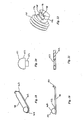
- a fastener assembly 6 comprises a fastener 8, a nut 14 and washer 16.
- the fastener 8 consists of a bolt portion 10 and a round collar portion 12.
- the fastener joins two steel plates 18 and 19 (together comprising a substrate) by passing through holes 20 and 21 in them and being tensioned.
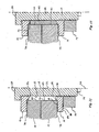
- Figure 12 shows a diametral half of the assembled and tensioned fastener 8 extending through the plates 18 and 19 with the collar 12, washer 16 and nut 14 engaged.
- the bolt 10 has a shank 22 with, at one end 24, an enlarged head 28 and, at the other end 26, a tail 30 which carries a thread 32 on a threaded portion 33 to suit the nut 14.
- the head 28 of the bolt 10 is a crown integrally formed with the shank 22.
- the head of the fastener 8 is thus the combination of the bolt head 28 and the collar 12.
- the bolt On the end of its tail 30 the bolt carries an axial protrusion 34 having a flat end face 37 and a peripheral surface 38.
- the peripheral surface 38 has a curved portion 40 and a flat face 42.
- the curved portion 40 has a cylindrical form whose axis is coincident with the major axis 36 of the bolt.
- the cylindrical form has a segment removed from its cylindrical shape so as to form the flat face 42 on the peripheral surface 38.
- the protrusion 34 thus has a non-circular cross-section.
- the cross section is D-shaped when viewed as a plane transverse to the axis 36 of the bolt 12.
- the curved portion 40 of the peripheral surface 38 provides a circular curved edge 43 in cross section.
- the flat face 42 on the periphery provides flat portion 44 on the cross-section.
- the maximum diameter of the protrusion 34 is smaller than the root diameter of the bolt thread 32.
- a short circular hole 56 forms a recess in about the centre of the flat face 42.
- the collar 12 comprises two half-collars 46 and 47 linked together by a backing strap 48.
- the collar 12 has a central aperture 51 forming a bore surrounded by a boss 54 and an outwardly extending flange 55 to form a stepped front face 58 and a flat rear face 50.
- Each half-collar 46 and 47 have corresponding respective boss portions 54a and 54b, flange portions 55a and 55b, front faces 58a and 58b, and rear faces 50a and 50b.
- the half-collars 46 and 47 are generally made from hardened steel and the strap 48 made from a strong adhesive tape which is tightly adhered to the rear faces 50a and 50b of respective half-collars.
- the half-collars 46 and 47 are separated by a narrow gap 45 which is bridged by the strap 48.
- the strap 48 provides a pair of hinges 52 and 53 whereby the half-collars can be folded over with their rear faces 50a and 50b abutting and the boss outwards.
- the portion of the strap bridging the gap 45 provides a length over which the strap can bend for hinging.
- the strap 48 is made of tape which has no significant resilience tending to open the collar out. In some less preferred embodiments the strap 48 may have some resilient property, but not enough by itself to fully open out the collar to the position shown in Figure 5 . In other less preferred embodiments the strap does have sufficient resilience to fully open out the collar to the position shown in Figure 5 .
- the washer 16 has a shape the same as the collar 12 but without the dividing gap nor backing strap.
- a central aperture 80 is surrounded by an axially extending boss 82 and an outwardly extending flange 84 to form a stepped front face 86 and a flat rear face 88 on the washer.
- the two half-collars 46 and 47 may be made by sawing or laser cutting a washer 16 in half, with the gap 45 being the width of the saw or laser cut.
- the half-collars may be separately formed as identical components.
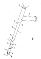
- the additional apparatus used to install the fastener assembly 6 comprises a tool 60 having a handle 62 mounted at right angles to, and part way along, an elongate shaft 64.
- the handle 62 is shown pointing downwards in the Figures.
- the shaft 64 is generally cylindrical for most of its length, with a stepped bar portion 63 extending from its rear end 65 to a non-cylindrical collar-supporting portion 66 of the shaft 64 and a bolt engagement portion 67 of the shaft attached to the collar-supporting portion 66.
- the handle 62 is adapted to be held by hand.
- the collar-supporting portion 66 is thinned and is described in detail below.
- the bolt-engagement portion 67 includes a D-shaped socket 68, on the front end 70 of the tool 60, which engages with the D-shaped protrusion 34 on the bolt.
- the bolt-engagement portion 67 also includes a manually moveable sleeve 76 and a latch 78 held captive by the sleeve 76.
- the collar-supporting portion 66 has a forward end 89 attached to the bolt-engagement portion 67 and a rearward end 90 attached to the cylindrical portion of the shaft 64.
- the collar-supporting portion is thinned in two ways. Towards its rearward end 90 it has a first thinned portion 91 which is merely a flattened peripheral portion of the overall cross section of the shaft and has a curved upper face 92 and a flat lower face 94.
- the second thinned portion 96 which is towards the forward end 89, is waisted.
- the second thinned portion 96 is a thin flat portion positioned along a diameter of the shaft, and with its main faces 99 and 100 oriented vertically when the handle 62 is pointed downwards, and a top edge 101 which is stepped inwards from the upper face 92 of the first thinned portion.
- the first and second thinned portions 91 and 96 overlap along a portion 93 of the collar-supporting portion 66 around the middle of the collar-supporting portion.
- the collar-supporting portion is smoothly flared out over a tapered transition region 135 by side faces 97 and 98 which extend from the diametrically aligned thin waisted portion 96 to the full diameter of the shaft at the shoulder 137.
- the side faces 97 and 98 are flat in this preferred embodiment, but may be curved if desired.
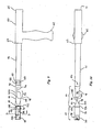
- the fastener 8 is shown being installed through two steel plates 18 and 19 by a person who has access to only the near side 72 of the plates. Holes 20 and 21 have been drilled in the plates 18 and 19 and, upon installation, the fastener 8 will pass through those holes and clamp the plates firmly together.
- the nut 14, washer 16 and collar 12 are first fed in that order onto the shaft 64 of the tool.
- the stepped front face 86 of the washer faces the front face 58 of the collar.
- the protrusion 34 on the bolt 10 is then clipped into the socket 68 and the sleeve 76 is adjusted to engage the latch 78 with the protrusion 34. and thereby prevent the protrusion from slipping out of the socket. That engagement of latch and protrusion is described later in this specification.
- the bolt 10 is then fed head first through the aligned holes 20 and 21 from the near-side 72 to the far side 74 of the plates while at the same time manually positioning the collar 12 on the collar supporting portion 66 of the shaft 64.
- the head 28 of the bolt is a loose clearance fit through the holes 20 and 21.
- the bolt passes fully through the holes using the tool 60 to support it on the far side 74.
- the collar is folded to hinge at 52 and 53 along the backing strap 48 and is positioned on the collar-supporting portion so that the hinge 52 spans and is supported by the thin upper edge 101 of the diametrically aligned waisted portion 96, the strap on the rear faces 50a and 50b lays substantially flat against side faces 99 and 100, and the end faces 102 and 104 of the half-collars and the hinge 53 are pressed into contact with the lower face 94 of the flattened peripheral portion 91.
- Portions 46 and 47 of the collar thus lie on respective opposite sides of the tool and the collar spans the overlap portion 93.
- the folded collar is thereby aligned to be pushed through the holes 20 and 21 by the tool when the collar supporting portion 66 is pushed through the holes.
- the leading edge 106 of the peripheral portion 91 presses on the inside wall 108 of the bore 51 of the collar to push the collar through the holes.
- the collar is collapsed from its fully opened out condition to a configuration which has a total height of about half its full diameter.
- the hinge 53 drops a little but the collar continues to hang from the hinge 52 with the rear faces 50a and 50b resting against or closely adjacent to the side faces 99 and 100 of the waisted portion 96.
- the handle 62 is then pulled to draw the collar supporting portion 66 of the tool back into the hole, thus causing the plate 18 to push the collar along the tapered transition region 135 to thereby unfold the collar 12.
- Rotation of the tool through 90° before pulling the handle back causes one of the half-collars 46 and 47 to drop, thereby partly opening the collar before it slides along the transition region 135, and thus requiring less force pulling on the handle to fully open the collar.
- Pulling the handle back further draws the shank 22 of the bolt back into the hole, with the head 28 pressing on the collar 12 to fully open the collar and thereby assemble the fastener 8.
- the half-collars 46 and 47 each carry a respective boss portion 54a and 54b on the front faces 58a and 58b adjacent the bore 51. These curved boss portions create a discontinuous boss 54 on the collar when the fastener 8 is assembled in use.
- the thickness of each boss portion in the diametrical direction is slightly less than the clearance between the shank 22 of the bolt and the wall 23 of the hole. The collar 12 is thus able to take up the position shown in Figure 12 where the boss 54 serves to prevent the collar and the bolt from moving laterally relative to the hole.
- the hinges 52 and 53 lie almost parallel to the axis 36 as the collar 12 is pushed through the holes while on the collar-supporting portion 66. Only the thickness of the peripheral portion 91 of the tool prevents completely parallel alignment of the hinges with the axis.
- the ability to nest the collar onto the tool with the collar's hinges aligned more parallel to the axis 36 when compared with the prior art allows the diameter and/or thickness of the collar to be increased for any given diameter hole through the substrate.
- the washer 16 and nut 14 are then engaged with the thread 11 and tightened by hand.
- the bolt is then released from the socket 68 and the nut is tightened to the desired tension using a spanner or power wrench as desired.
- the washer 16 has its boss 82 extending from the front face 86 in contact with the steel plate 19.
- the outside diameter of the boss 82 is slightly smaller than the diameter of the hole 21, so the boss fits neatly into the entry of the hole 21 and thus serves to positively locate the shank 22 central to the hole in the same manner as the boss 54 on the collar 12 act in relation to the hole 20.
- the rear end 71 of the shaft 64 has a D-shaped socket 75 formed therein which may be used to restrain the bolt 10 from turning while the nut 14 is being tightened.
- the collar shown folded in Figure 2 is oriented so that at the completion of installation the backing strap 48 finishes being pressed between the bolt head 10 and the rear faces 50a and 50b of the half-collars.
- the tool 60 as described above is entirely of metal construction, although it may alternatively be constructed entirely from appropriately chosen engineering plastics material(s).
- the portions 61, 66 and 67 are socketed onto each other using socket joints 141 and 161 which are each fastened by respective pins 138 and 164 inserted through diametrical holes 133 and 163 drilled through the socket joints.
- the bolt-engagement portion 67 and collar supporting portion 66 may thus be conveniently replaced if worn or damaged.
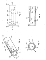
- the bolt engagement portion 67 comprises a tubular body portion 110 which has a bore 111 with a D-shaped cross-section and has a wall 116 of non-uniform thickness.
- a leading end 112 of the body portion 110 has an outwardly extending flange 128 around its perimeter.
- the inboard end 112 of the portion 110 is fastened by socket joint 141 to the collar supporting portion 66.
- the curved face 114 of the bore 111 is on a portion of the wall 116 which is thinner than the portion 118 which forms the flat face 120 in the bore 111.
- an elongate channel 122 having a flat bottom 123 and rounded ends 124 and 126.
- the end 124 closest the leading end 112 of the tube has a hole 130 extending radially through the wall 118 into the bore 111, the diameter of the hole 130 being the same as the width of the channel 122.
- the inboard end 126 of the channel which is that end closest the handle 62, has a smaller hole 132 extending from the channel radially into the bore 111.
- a hole 133 diametrically completely through the tube is a hole 133 diametrically completely through the tube.
- the leading end 134 of the collar-supporting portion 66 has a protuberance 136 which neatly fits into the D-shaped bore at the inboard end 113 to form the socket joint 141.
- a shoulder 137 is formed on the collar-supporting portion where the collar-supporting portion expands from the protuberance 136 to the circumferentially outer surface of the leading end 134.
- a circular pin 138 forming an interference fit through the hole 133 and a corresponding hole 139 through the protuberance 136 fastens the tubular body portion to the collar supporting portion.
- a similar socket joint 161 joins the collar-supporting portion 66 to the main body 61.
- joint 161 is formed by a cylindrical protrusion on the collar-retaining portion engaging with a socket 162 on the main body portion and retained by a pin 164 through a diametrical hole 163.
- the pin 164 is selected to break, thus allowing the joint 161 to rotate, if the torque on the joint exceeds a value somewhat less than that required to damage thinned portions 91 and 96.
- the retaining clip 78 shown in Figures 18 and 19 forms a latch in the bolt-engagement portion 67.
- the body 142 of the latch 78 is an elongate flat strip of metal having rounded ends 144 and 146 termed the latching end and the retained end respectively.
- On the latching end 144 is a hemispherically-ended stud 148, while at the retained end 146 of the latch 78, the strip metal of its body 142 is narrowed and turned at right angles to extend as a narrow tab 150 in the same direction as the stud 148.
- the stud has a hemispherical end 151 rising from a short cylindrical portion 152.
- the length of the cylindrical portion 152 is about the same as the length of the hole 130.
- the body 142 of the latch has a hole 153 therethrough into which a tail 154 of the stud 148 is expanded in order to fasten the stud 148 to the body 142.
- the latch 78 is located with its body 142 resting in the channel 122, its stud 148 extending inwards into the larger hole 130 and the tab 150 extending inwards into the smaller hole 132. While the tab 150 is not long enough to project past the flat face 120 into the bore 111, the stud 148 acts as a moveable member which is long enough to extend into the bore when depressed but nevertheless short enough to withdraw from the bore.
- the thin-walled tubular sleeve 76 is held captive on the outside of the tubular body portion 110 such that the sleeve is free to slide backwards and forwards along the length of the tubular body portion and also slide around it.
- the sleeve is held captive by the outwardly extending flange 128 at the leading end 112 and, at the inboard end 113 by the shoulder 137 on the collar-supporting portion.
- the thickness of the body 142 of the latch is such that when the sleeve 76 slides forwards to the leading end 112, the stud 148 is held down at maximum projection in the hole 130 and the hemispherical end 151 protrudes from the flat wall 118 inside the socket and engages into the recess 56 in the bolt.
- the latch may tilt lengthways so that the stud 138 retracts through the flat wall 118 of the socket, thus disengaging from the hole 56, and the protrusion 34 is then free to slide out of the socket 68.
- the sleeve 76 is slid back towards the handle of the tool and the protrusion 34 on the bolt is slipped into the socket 68. This forms an interface 121 between the flat faces 42 and 120 and between the curved faces 40 and 114. The sleeve 76 is then slid forward so depressing the stud across the interface 121 and into the recess 56. The body 142 of the latch is prevented from moving radially outwards by the sleeve 76. The stud mechanically locks the bolt to the socket. The bolt at this stage cannot be pulled from the socket without something breaking or irreversibly distorting. This constitutes a positive location of the head of the stud into the recess and does not depend upon any spring loading mechanism.
- Typical nominal dimensions for a fastener used with 30 mm diameter holes in the steel plates 18 and 19 would be:
- Figure 13 shows a second embodiment of the invention which is preferred for joins under high shear loading.
- a sleeve 162 is fed onto the shaft 64 of the tool between the collar and the washer and is pressed along over the shank 22 of the bolt into the holes 20 and 21.
- the sleeve 162 is sized so that the sum of its length plus the heights of the bosses on the collar and washer is a little shorter than the total length through the plates 18 and 19, so that the sleeve substantially fills the annular gap lengthwise but is not axially compressed during tightening of the nut 14.
- the inside and outside diameters of the sleeve 162 are selected to be a loose (but not sloppy) sliding fit to the bolt 10 and the holes 20 and 21 respectively.
- the sleeve 162 thus neatly fills the annular gap between the bolt and the walls of the holes 21 and 22, so there can be no significant movement lateral to the hole.
- the bosses on the collar and washer are typically a little looser fit than the sleeve 162 into the holes.
- a sleeve applied to the example fastener dimensioned above would have a nominal internal diameter of 20mm and outside diameter of 29mm. For joints under high shear, this is equivalent to having a fastener with a 29mm shank through the 30mm hole. For a cost-effective greater increase in shear strength of the fastening, a higher strength steel may be used for the sleeve than is used for the bolt. If there is little or no shear component to the loading, then the sleeve may be omitted from the assembly if required as shown in Figure 12 .
- a preferred alterative configuration of the recess in the protrusion is shown on the bolt 170 in Figure 22 .
- the bolt 170 works with the same tool 60 as described above.
- the recess previously described is a circular hole 56
- the recess in Figure 22 is a slot 172 formed across the flattened face 174.
- Such a slot can be formed in the same operation as that which machines the flattened face 174 and thus a further drilling operation to make the hole is not required.
- slot 172 shown in Figure 22 has a rectangular cross section with a flat bottom 176 and flat side walls 178
- the slot may alternatively have a cross section which is semicircular, V-shaped, or any other shape which provides a positive interlock with a correspondingly shaped mating stud on the latch 78.
- the nut 14 and washer 16 are combined into a single item such that the nut has a boss corresponding to boss 82 which in use engages into the hole 21 as the nut is tightened.
- the collar supporting portion 66 is welded to (or otherwise integrally formed with) the leading end of the main body portion 61 of the tool rather than having pinned socket joint 161.
- the collar-supporting portion 66 may be welded to (or otherwise integrally formed with) the bolt-engaging portion 67 rather than having the pinned socket joint 141.
- the protrusion 34 and engaging socket have simple cylindrical forms so that, unless the stud is engaged into the recess, the protrusion is free to rotate in the socket.
Landscapes
- Engineering & Computer Science (AREA)
- Mechanical Engineering (AREA)
- General Engineering & Computer Science (AREA)
- Dowels (AREA)
Claims (14)
- Procédé pour installer un élément de fixation fileté (8) à partir d'un côté (72) d'un trou (20, 21) qui traverse un substrat (18, 19), ledit élément de fixation comprenant :(a) un boulon (10) qui comporte :(i) une partie de tête élargie (28), à une extrémité,(ii) une partie de queue filetée (33), à l'extrémité opposée à la tête, et(iii) une partie d'accouplement d'outil (34) qui s'étend à partir de la partie de queue filetée (33), et(b) une bague du type rondelle (12) qui est traversée par une ouverture (51),le procédé comprenant les étapes qui consistent :(a) à accoupler la partie d'accouplement d'outil (34) à une partie d'accouplement de boulon (67) d'un outil (60),(b) à passer le boulon entièrement à travers le trou, la tête la première à partir d'un côté, à savoir le côté proche (72) du trou, jusqu'au côté éloigné (74) du trou,(c) à supporter le boulon (10) sur le côté éloigné (74) du trou à l'aide de l'outil qui traverse le trou,(d) à passer la bague (12) entièrement à travers le trou (20, 21) tout en la supportant avec l'outil (60) qui traverse une ouverture (51) et le trou, la bague étant pliée avec ses parties (46, 47) placées sur les côtés opposés respectifs de l'outil, quand ladite bague passe à travers le trou ;(e) à amener le boulon (10) et la bague (12) à s'assembler pour former l'élément de fixation fileté (8) qui comporte une tête plus grande que le trou, sur le côté éloigné du trou, une tige (22) à l'intérieur du trou, et une partie de la queue filetée sur le côté proche du trou ;(f) à accoupler un écrou (14) à la partie de queue filetée (33), sur le côté proche (72), et à tourner l'écrou pour serrer l'élément de fixation ; et(g) à enlever l'outil (60) de l'élément de fixation (8) ; caractérisé en ce que la partie d'accouplement de boulon (67) et la partie d'accouplement d'outil (34) s'accouplent le long d'une interface (38), et une séparation de la partie d'accouplement de boulon et de la partie d'accouplement d'outil est empêchée par un élément mobile (78) qui accouple ladite partie d'accouplement de boulon et ladite partie d'accouplement d'outil sur toute cette interface.
- Procédé selon la revendication 1, caractérisé en ce que la partie d'accouplement d'outil (34) comprend une saillie (34) qui s'étend à partir de la partie de queue filetée (33), la partie d'accouplement de boulon comprend une douille (68), et la saillie et la douille s'accouplent avec un ajustement glissant le long d'une interface (38) alignée, dans un sens axial, par rapport au boulon.
- Procédé selon la revendication 2, caractérisé en ce que la saillie (34) comprend un creux (56), et la partie d'accouplement de boulon comprend un élément mobile (148) qui entre dans le creux pour empêcher ainsi que la saillie (34) ne sorte de la douille (68).
- Procédé selon l'une quelconque des revendications précédentes, caractérisé en ce que l'élément mobile (78) est actionné manuellement vers sa position d'accouplement dans le creux (56), grâce au glissement manuel d'un manchon extérieur (76) sur la partie d'accouplement de boulon (67).
- Procédé selon la revendication 4, caractérisé en ce que l'élément mobile (78) comprend une partie saillante (148) sur une bande aplatie (142).
- Procédé selon la revendication 5, caractérisé en ce que lorsque l'élément mobile (148) est actionné vers sa position d'accouplement, le manchon extérieur (76) empêche la bande (142) de se déplacer radialement vers l'extérieur par rapport à la partie de queue filetée (33).
- Procédé selon l'une quelconque des revendications 2 à 6, caractérisé en ce que la saillie (34) a une section transversale non circulaire de manière à empêcher la rotation de ladite saillie dans la douille (68).
- Procédé selon la revendication 7, caractérisé en ce que ladite section transversale non circulaire a une partie rectiligne, de telle sorte que la saillie a une face aplatie (42) sur sa périphérie (38).
- Procédé selon la revendication 7, caractérisé en ce que ladite section transversale non circulaire a la forme d'un D, dont la partie arrondie (40) est circulaire et présente un centre qui est situé sur l'axe (36) de la partie de queue filetée, de telle sorte que la saillie (34) a une face cylindrique (40) et une face aplatie (42) sur sa périphérie (38).
- Procédé selon l'une quelconque des revendications précédentes, caractérisé en ce que l'outil (60) a une poignée (62), une tige (64) fixée à la poignée, et ladite partie d'accouplement de boulon (67) fixée à une extrémité de ladite tige (64), ladite tige comprenant sur des parties respectives de sa longueur :- une partie périphérique aplatie (91), et- une partie aplatie diamétralement alignée (96) qui se trouve entre la partie périphérique aplatie (91) et la partie d'accouplement de boulon (67) et qui s'étend en direction de la poignée (62) pour empiéter sur ladite partie périphérique aplatie (91),
et étant précisé que la bague (12), lorsqu'elle passe à travers le trou (20, 21), est supportée au niveau d'une première partie pliée (52) par ladite partie diamétralement alignée (96). - Procédé selon la revendication 10, caractérisé en ce que la bague (12), lorsqu'elle passe à travers le trou (20, 21), est pliée, avec ses parties (46, 47) placées sur les côtés opposés respectifs de la partie diamétralement alignée (96), ladite bague couvrant l'empiétement (93) de la partie périphérique aplatie et de la partie diamétralement alignée, et une seconde partie pliée (53) de la bague bute contre la partie périphérique aplatie (91).
- Boulon (10) comprenant(i) une partie de tête élargie (28), à une extrémité,(ii) une partie de queue filetée (33), à l'extrémité oposée à la tête,(iii) un grand axe (36) sur la longueur du boulon, et(iv) une saillie (34) qui s'étend à partir de la partie de queue filetée (33), ladite saillie ayant une section transversale non circulaire, transversalement par rapport audit axe, et présentant un creux (56),
caractérisé en ce que la section transversale non circulaire a la forme d'un D, dont la partie arrondie est circulaire et présente un centre qui est situé sur le grand axe (36) de telle sorte que la saillie a une face cylindrique (40) sur sa périphérie et une face aplatie (42) dans laquelle est formé le creux (56), ce creux étant apte, lors d'une utilisation, à recevoir un élément mobile (148) prévu sur un outil (60), pour empêcher ainsi que la douille ne sorte de l'outil. - Elément de fixation fileté caractérisé en ce qu'il comprend la combinaison d'un boulon (10) selon la revendication 12 et d'une bague du type rondelle (12), ladite bague comprenant deux moitiés rigides (46, 47) reliées par des parties articulées souplement (52, 53).
- Elément de fixation fileté selon la revendication 13, caractérisé en ce que la bague (12), lorsqu'elle a une configuration plate, dépliée, a une dimension extérieure plus grande que le diamètre de la plus petite ouverture à travers laquelle la tête de boulon (28) peut passer, et ladite bague définissant une ouverture (51) à travers laquelle la partie de queue filetée (33) peut passer, mais pas la tête de boulon (28).
Priority Applications (1)
| Application Number | Priority Date | Filing Date | Title |
|---|---|---|---|
| EP06014835.0A EP1880800B1 (fr) | 2006-07-17 | 2006-07-17 | Élément de fixation et méthode d'installation |
Applications Claiming Priority (1)
| Application Number | Priority Date | Filing Date | Title |
|---|---|---|---|
| EP06014835.0A EP1880800B1 (fr) | 2006-07-17 | 2006-07-17 | Élément de fixation et méthode d'installation |
Publications (2)
| Publication Number | Publication Date |
|---|---|
| EP1880800A1 EP1880800A1 (fr) | 2008-01-23 |
| EP1880800B1 true EP1880800B1 (fr) | 2015-11-18 |
Family
ID=37451023
Family Applications (1)
| Application Number | Title | Priority Date | Filing Date |
|---|---|---|---|
| EP06014835.0A Not-in-force EP1880800B1 (fr) | 2006-07-17 | 2006-07-17 | Élément de fixation et méthode d'installation |
Country Status (1)
| Country | Link |
|---|---|
| EP (1) | EP1880800B1 (fr) |
Families Citing this family (7)
| Publication number | Priority date | Publication date | Assignee | Title |
|---|---|---|---|---|
| US9145908B2 (en) | 2011-12-16 | 2015-09-29 | Ev Ip Lp | Blind fastener |
| JP2015218902A (ja) * | 2014-05-21 | 2015-12-07 | 正雄 佐藤 | 2穴式丸形ボルト。 |
| CN108131373A (zh) * | 2018-02-08 | 2018-06-08 | 张丽 | 一种短尾拉铆紧固套件、拆装工具及拆装工具的使用方法 |
| JP7292127B2 (ja) * | 2019-06-25 | 2023-06-16 | 株式会社青山製作所 | 締結具 |
| CN110125596A (zh) * | 2019-06-28 | 2019-08-16 | 云南力帆骏马车辆有限公司 | 焊接工装定位结构及定位方法 |
| CN110900519B (zh) * | 2019-11-27 | 2021-10-08 | 同济大学 | 一种用于分段式分体连接单边螺栓紧固件的安装工具 |
| CN111365347B (zh) * | 2020-03-16 | 2022-02-15 | 中国北方车辆研究所 | 一种用于相对运动部件间位移检测的带孔扁头螺栓 |
Family Cites Families (2)
| Publication number | Priority date | Publication date | Assignee | Title |
|---|---|---|---|---|
| AUPP618398A0 (en) * | 1998-09-25 | 1998-10-22 | Ajax Technology Centre Pty Ltd | Threaded fasteners |
| US20040208722A1 (en) * | 2003-04-17 | 2004-10-21 | Pop-In Pop-Out, Inc. | Fastener adapted for use with a structural member |
-
2006
- 2006-07-17 EP EP06014835.0A patent/EP1880800B1/fr not_active Not-in-force
Also Published As
| Publication number | Publication date |
|---|---|
| EP1880800A1 (fr) | 2008-01-23 |
Similar Documents
| Publication | Publication Date | Title |
|---|---|---|
| US7373709B2 (en) | Method of installing a blind threaded fastener | |
| EP1861628B1 (fr) | Verrou a bride a boulon et a fixation rapide | |
| US6568894B2 (en) | Fastener devices, such as lock-pins | |
| US7156424B2 (en) | Coupling assembly with retention mechanism | |
| EP1861626B2 (fr) | Ensemble d'ancrage pour piece de fixation | |
| US7226261B1 (en) | Toggle assembly | |
| US8966874B2 (en) | Shackle assembly with locking pin | |
| US11053968B1 (en) | Blind bolt | |
| US5219254A (en) | Expandable fastener and locking means therefor | |
| JP2005517876A (ja) | 拡大可能のコレットアンカー装置、その構成要素並びにそれの製造方法及び使用方法 | |
| EP1880800B1 (fr) | Élément de fixation et méthode d'installation | |
| US20160327076A1 (en) | Fastener for securing together two panels | |
| NZ511290A (en) | Blind bolting | |
| CA2552448C (fr) | Ameliorations concernant le boulonnage aveugle | |
| US9714674B1 (en) | Fastener device | |
| JP7786960B2 (ja) | ワンタッチ式ファスナー | |
| JPH0854009A (ja) | 拡張ボルト | |
| CA2592203A1 (fr) | Dispositif pre-positionnable d'ancrage a barrette articulee | |
| WO1992009813A1 (fr) | Dispositif de fixation a insertion | |
| US11421722B1 (en) | Blind bolt and tool combination | |
| AU766347B2 (en) | Blind bolting | |
| WO2014099130A1 (fr) | Ensemble de mousqueton doté d'une goupille de verrouillage | |
| KR19980064299U (ko) | 풀림방지너트 | |
| HK1081409A1 (zh) | 用於连接至少两个手链链节的铰接装置 |
Legal Events
| Date | Code | Title | Description |
|---|---|---|---|
| PUAI | Public reference made under article 153(3) epc to a published international application that has entered the european phase |
Free format text: ORIGINAL CODE: 0009012 |
|
| AK | Designated contracting states |
Kind code of ref document: A1 Designated state(s): AT BE BG CH CY CZ DE DK EE ES FI FR GB GR HU IE IS IT LI LT LU LV MC NL PL PT RO SE SI SK TR |
|
| AX | Request for extension of the european patent |
Extension state: AL BA HR MK YU |
|
| 17P | Request for examination filed |
Effective date: 20080709 |
|
| 17Q | First examination report despatched |
Effective date: 20080808 |
|
| AKX | Designation fees paid |
Designated state(s): AT BE BG CH CY CZ DE DK EE ES FI FR GB GR HU IE IS IT LI LT LU LV MC NL PL PT RO SE SI SK TR |
|
| GRAP | Despatch of communication of intention to grant a patent |
Free format text: ORIGINAL CODE: EPIDOSNIGR1 |
|
| GRAS | Grant fee paid |
Free format text: ORIGINAL CODE: EPIDOSNIGR3 |
|
| GRAA | (expected) grant |
Free format text: ORIGINAL CODE: 0009210 |
|
| AK | Designated contracting states |
Kind code of ref document: B1 Designated state(s): AT BE BG CH CY CZ DE DK EE ES FI FR GB GR HU IE IS IT LI LT LU LV MC NL PL PT RO SE SI SK TR |
|
| REG | Reference to a national code |
Ref country code: GB Ref legal event code: FG4D |
|
| REG | Reference to a national code |
Ref country code: CH Ref legal event code: EP |
|
| REG | Reference to a national code |
Ref country code: AT Ref legal event code: REF Ref document number: 761288 Country of ref document: AT Kind code of ref document: T Effective date: 20151215 |
|
| REG | Reference to a national code |
Ref country code: IE Ref legal event code: FG4D |
|
| REG | Reference to a national code |
Ref country code: DE Ref legal event code: R096 Ref document number: 602006047310 Country of ref document: DE |
|
| REG | Reference to a national code |
Ref country code: NL Ref legal event code: MP Effective date: 20160218 |
|
| REG | Reference to a national code |
Ref country code: LT Ref legal event code: MG4D |
|
| REG | Reference to a national code |
Ref country code: AT Ref legal event code: MK05 Ref document number: 761288 Country of ref document: AT Kind code of ref document: T Effective date: 20151118 |
|
| PG25 | Lapsed in a contracting state [announced via postgrant information from national office to epo] |
Ref country code: IS Free format text: LAPSE BECAUSE OF FAILURE TO SUBMIT A TRANSLATION OF THE DESCRIPTION OR TO PAY THE FEE WITHIN THE PRESCRIBED TIME-LIMIT Effective date: 20160318 Ref country code: IT Free format text: LAPSE BECAUSE OF FAILURE TO SUBMIT A TRANSLATION OF THE DESCRIPTION OR TO PAY THE FEE WITHIN THE PRESCRIBED TIME-LIMIT Effective date: 20151118 Ref country code: NL Free format text: LAPSE BECAUSE OF FAILURE TO SUBMIT A TRANSLATION OF THE DESCRIPTION OR TO PAY THE FEE WITHIN THE PRESCRIBED TIME-LIMIT Effective date: 20151118 Ref country code: ES Free format text: LAPSE BECAUSE OF FAILURE TO SUBMIT A TRANSLATION OF THE DESCRIPTION OR TO PAY THE FEE WITHIN THE PRESCRIBED TIME-LIMIT Effective date: 20151118 Ref country code: LT Free format text: LAPSE BECAUSE OF FAILURE TO SUBMIT A TRANSLATION OF THE DESCRIPTION OR TO PAY THE FEE WITHIN THE PRESCRIBED TIME-LIMIT Effective date: 20151118 |
|
| REG | Reference to a national code |
Ref country code: DE Ref legal event code: R082 Ref document number: 602006047310 Country of ref document: DE Representative=s name: HERNANDEZ, YORCK, DIPL.-ING., DE |
|
| PG25 | Lapsed in a contracting state [announced via postgrant information from national office to epo] |
Ref country code: PL Free format text: LAPSE BECAUSE OF FAILURE TO SUBMIT A TRANSLATION OF THE DESCRIPTION OR TO PAY THE FEE WITHIN THE PRESCRIBED TIME-LIMIT Effective date: 20151118 Ref country code: PT Free format text: LAPSE BECAUSE OF FAILURE TO SUBMIT A TRANSLATION OF THE DESCRIPTION OR TO PAY THE FEE WITHIN THE PRESCRIBED TIME-LIMIT Effective date: 20160318 Ref country code: GR Free format text: LAPSE BECAUSE OF FAILURE TO SUBMIT A TRANSLATION OF THE DESCRIPTION OR TO PAY THE FEE WITHIN THE PRESCRIBED TIME-LIMIT Effective date: 20160219 Ref country code: AT Free format text: LAPSE BECAUSE OF FAILURE TO SUBMIT A TRANSLATION OF THE DESCRIPTION OR TO PAY THE FEE WITHIN THE PRESCRIBED TIME-LIMIT Effective date: 20151118 Ref country code: FI Free format text: LAPSE BECAUSE OF FAILURE TO SUBMIT A TRANSLATION OF THE DESCRIPTION OR TO PAY THE FEE WITHIN THE PRESCRIBED TIME-LIMIT Effective date: 20151118 Ref country code: SE Free format text: LAPSE BECAUSE OF FAILURE TO SUBMIT A TRANSLATION OF THE DESCRIPTION OR TO PAY THE FEE WITHIN THE PRESCRIBED TIME-LIMIT Effective date: 20151118 Ref country code: LV Free format text: LAPSE BECAUSE OF FAILURE TO SUBMIT A TRANSLATION OF THE DESCRIPTION OR TO PAY THE FEE WITHIN THE PRESCRIBED TIME-LIMIT Effective date: 20151118 |
|
| REG | Reference to a national code |
Ref country code: FR Ref legal event code: PLFP Year of fee payment: 11 |
|
| PG25 | Lapsed in a contracting state [announced via postgrant information from national office to epo] |
Ref country code: CZ Free format text: LAPSE BECAUSE OF FAILURE TO SUBMIT A TRANSLATION OF THE DESCRIPTION OR TO PAY THE FEE WITHIN THE PRESCRIBED TIME-LIMIT Effective date: 20151118 |
|
| REG | Reference to a national code |
Ref country code: DE Ref legal event code: R097 Ref document number: 602006047310 Country of ref document: DE |
|
| PG25 | Lapsed in a contracting state [announced via postgrant information from national office to epo] |
Ref country code: EE Free format text: LAPSE BECAUSE OF FAILURE TO SUBMIT A TRANSLATION OF THE DESCRIPTION OR TO PAY THE FEE WITHIN THE PRESCRIBED TIME-LIMIT Effective date: 20151118 Ref country code: SK Free format text: LAPSE BECAUSE OF FAILURE TO SUBMIT A TRANSLATION OF THE DESCRIPTION OR TO PAY THE FEE WITHIN THE PRESCRIBED TIME-LIMIT Effective date: 20151118 Ref country code: RO Free format text: LAPSE BECAUSE OF FAILURE TO SUBMIT A TRANSLATION OF THE DESCRIPTION OR TO PAY THE FEE WITHIN THE PRESCRIBED TIME-LIMIT Effective date: 20151118 Ref country code: DK Free format text: LAPSE BECAUSE OF FAILURE TO SUBMIT A TRANSLATION OF THE DESCRIPTION OR TO PAY THE FEE WITHIN THE PRESCRIBED TIME-LIMIT Effective date: 20151118 |
|
| PLBE | No opposition filed within time limit |
Free format text: ORIGINAL CODE: 0009261 |
|
| STAA | Information on the status of an ep patent application or granted ep patent |
Free format text: STATUS: NO OPPOSITION FILED WITHIN TIME LIMIT |
|
| 26N | No opposition filed |
Effective date: 20160819 |
|
| PG25 | Lapsed in a contracting state [announced via postgrant information from national office to epo] |
Ref country code: SI Free format text: LAPSE BECAUSE OF FAILURE TO SUBMIT A TRANSLATION OF THE DESCRIPTION OR TO PAY THE FEE WITHIN THE PRESCRIBED TIME-LIMIT Effective date: 20151118 |
|
| PG25 | Lapsed in a contracting state [announced via postgrant information from national office to epo] |
Ref country code: BE Free format text: LAPSE BECAUSE OF FAILURE TO SUBMIT A TRANSLATION OF THE DESCRIPTION OR TO PAY THE FEE WITHIN THE PRESCRIBED TIME-LIMIT Effective date: 20151118 |
|
| REG | Reference to a national code |
Ref country code: CH Ref legal event code: PL |
|
| PG25 | Lapsed in a contracting state [announced via postgrant information from national office to epo] |
Ref country code: MC Free format text: LAPSE BECAUSE OF FAILURE TO SUBMIT A TRANSLATION OF THE DESCRIPTION OR TO PAY THE FEE WITHIN THE PRESCRIBED TIME-LIMIT Effective date: 20151118 |
|
| PG25 | Lapsed in a contracting state [announced via postgrant information from national office to epo] |
Ref country code: LI Free format text: LAPSE BECAUSE OF NON-PAYMENT OF DUE FEES Effective date: 20160731 Ref country code: CH Free format text: LAPSE BECAUSE OF NON-PAYMENT OF DUE FEES Effective date: 20160731 |
|
| REG | Reference to a national code |
Ref country code: IE Ref legal event code: MM4A |
|
| REG | Reference to a national code |
Ref country code: FR Ref legal event code: PLFP Year of fee payment: 12 |
|
| PG25 | Lapsed in a contracting state [announced via postgrant information from national office to epo] |
Ref country code: IE Free format text: LAPSE BECAUSE OF NON-PAYMENT OF DUE FEES Effective date: 20160717 |
|
| PG25 | Lapsed in a contracting state [announced via postgrant information from national office to epo] |
Ref country code: LU Free format text: LAPSE BECAUSE OF NON-PAYMENT OF DUE FEES Effective date: 20160717 |
|
| PG25 | Lapsed in a contracting state [announced via postgrant information from national office to epo] |
Ref country code: HU Free format text: LAPSE BECAUSE OF FAILURE TO SUBMIT A TRANSLATION OF THE DESCRIPTION OR TO PAY THE FEE WITHIN THE PRESCRIBED TIME-LIMIT; INVALID AB INITIO Effective date: 20060717 Ref country code: CY Free format text: LAPSE BECAUSE OF FAILURE TO SUBMIT A TRANSLATION OF THE DESCRIPTION OR TO PAY THE FEE WITHIN THE PRESCRIBED TIME-LIMIT Effective date: 20151118 |
|
| PG25 | Lapsed in a contracting state [announced via postgrant information from national office to epo] |
Ref country code: TR Free format text: LAPSE BECAUSE OF FAILURE TO SUBMIT A TRANSLATION OF THE DESCRIPTION OR TO PAY THE FEE WITHIN THE PRESCRIBED TIME-LIMIT Effective date: 20151118 |
|
| REG | Reference to a national code |
Ref country code: FR Ref legal event code: PLFP Year of fee payment: 13 |
|
| PG25 | Lapsed in a contracting state [announced via postgrant information from national office to epo] |
Ref country code: BG Free format text: LAPSE BECAUSE OF FAILURE TO SUBMIT A TRANSLATION OF THE DESCRIPTION OR TO PAY THE FEE WITHIN THE PRESCRIBED TIME-LIMIT Effective date: 20151118 |
|
| PGFP | Annual fee paid to national office [announced via postgrant information from national office to epo] |
Ref country code: DE Payment date: 20190719 Year of fee payment: 14 Ref country code: FR Payment date: 20190719 Year of fee payment: 14 |
|
| PGFP | Annual fee paid to national office [announced via postgrant information from national office to epo] |
Ref country code: GB Payment date: 20190719 Year of fee payment: 14 |
|
| REG | Reference to a national code |
Ref country code: DE Ref legal event code: R119 Ref document number: 602006047310 Country of ref document: DE |
|
| GBPC | Gb: european patent ceased through non-payment of renewal fee |
Effective date: 20200717 |
|
| PG25 | Lapsed in a contracting state [announced via postgrant information from national office to epo] |
Ref country code: FR Free format text: LAPSE BECAUSE OF NON-PAYMENT OF DUE FEES Effective date: 20200731 Ref country code: GB Free format text: LAPSE BECAUSE OF NON-PAYMENT OF DUE FEES Effective date: 20200717 |
|
| PG25 | Lapsed in a contracting state [announced via postgrant information from national office to epo] |
Ref country code: DE Free format text: LAPSE BECAUSE OF NON-PAYMENT OF DUE FEES Effective date: 20210202 |