EP1880905A2 - Pare-chocs avec éléments de support - Google Patents
Pare-chocs avec éléments de support Download PDFInfo
- Publication number
- EP1880905A2 EP1880905A2 EP07014123A EP07014123A EP1880905A2 EP 1880905 A2 EP1880905 A2 EP 1880905A2 EP 07014123 A EP07014123 A EP 07014123A EP 07014123 A EP07014123 A EP 07014123A EP 1880905 A2 EP1880905 A2 EP 1880905A2
- Authority
- EP
- European Patent Office
- Prior art keywords
- bumper
- edge
- holder
- longitudinal
- bumper according
- Prior art date
- Legal status (The legal status is an assumption and is not a legal conclusion. Google has not performed a legal analysis and makes no representation as to the accuracy of the status listed.)
- Granted
Links
Images



Classifications
-
- B—PERFORMING OPERATIONS; TRANSPORTING
- B60—VEHICLES IN GENERAL
- B60R—VEHICLES, VEHICLE FITTINGS, OR VEHICLE PARTS, NOT OTHERWISE PROVIDED FOR
- B60R19/00—Wheel guards; Radiator guards, e.g. grilles; Obstruction removers; Fittings damping bouncing force in collisions
- B60R19/02—Bumpers, i.e. impact receiving or absorbing members for protecting vehicles or fending off blows from other vehicles or objects
- B60R19/24—Arrangements for mounting bumpers on vehicles
- B60R19/26—Arrangements for mounting bumpers on vehicles comprising yieldable mounting means
- B60R19/34—Arrangements for mounting bumpers on vehicles comprising yieldable mounting means destroyed upon impact, e.g. one-shot type
Definitions
- the invention relates to a bumper with - on this to be mounted - projecting from her brackets for attachment to longitudinal members of a vehicle, wherein at the bumper at a distance from each other as a pressure belt or tension belt arranged profile walls and a pair of connecting flank walls form a hollow profile.
- the holder can be configured as at least one side wall and two subsequent thereto transverse walls exhibiting hollow profile with a longitudinal member associated hollow profile support section and the hollow profile of the bumper optionally be curved at least in the region of the brackets relative to a transverse plane of the longitudinal axis of the vehicle.
- a bumper with the longitudinal axis of its longitudinal member crossing plate-like brackets describes the EP 0 718 158 B1 pointing out that in addition to the cross-sectional shape of the bumper and the design of the connection to the vehicle longitudinal beam affects their dimensional stability and their compensation capacity for the incident deformation energy.
- brackets for example US-A-5,080,410 or US-A-4,563,028 - which, however, hardly contribute to the improvement of the dimensional stability of a bumper in an impact.
- the inventor has set the goal, in a bumper of the type mentioned, which has a high degree of dimensional stability with sufficient compensation capacity for the incident deformation energy at low weight, a way to create a stable connection of a bumper to the To allow associated vehicle and to significantly reduce deformation under impact load.
- the bumper and support unit is provided with compensation elements which limit deformations on the support which are triggered by pressure forces influencing the bumper, for example by the force of a collision.
- the holder is welded at least one end and is equipped near the weld with at least one hole-like wall opening in its wall.
- the described compensation can also be effected by at least one blind slot, which is cut into the edge region of the holder remote from the bumper and inclined to a diametral plane crossing its center line. At the blind slot or at a pair of both sides of the center line and mutually parallel blind slots ends the deformation load.
- Another compensation element should be designed as a rod. This is - similar to the blind slot described above - assigned to the bumper distal edge region of the holder as a inclined to a center line diametrical plane profile that protrudes from a lower weld and rests against the surface of the wall. Preference is given to two parallel bars on the outer surface of the wall. In the case of a deformation load also ends their creative force on these rods.
- the holder contains the wall openings and is equipped on its outer surface with those rods.
- Another type of compensation according to the invention is based on a pair of longitudinal or end slots starting from the front edge of the bumper, each of which is arranged in one of the flank walls in its region adjoining the inner or tension belt of the bumper.
- the bracket with the tension belt are connected by a weld so that a part of the wall of this bracket is added below the end slots to the bumper.
- the end slot advantageously engages over the centerline of the holder, and the end edge of the end slot is adjacent the centerline of the holder. As low, it has been found to choose the length of the end slot shorter than the diameter of the holder.
- these longitudinal or end slots of the bumper may be associated with the wall openings of the holder and / or the end slots extending from the peripheral edge thereof.
- the rods which conform to the outer or surface of the holder can also be used.
- the bumper far end of - consisting of a hollow profile approximately rectangular cross-section - bracket or its frame-like end edge abuts a rear plate as a connecting member, which is preferably welded to the bracket.
- the longitudinal edges of the rear plate should be longer than their transverse edges, and should also be formed on one of the transitions between a transverse edge and a longitudinal edge of the latter a plate portion with a part-circular - preferably a semicircular - outer edge. Its center determines the position of a breakthrough, thanks to which the rear plate prefixed to a corresponding counter-member of the longitudinal member will be able.
- openings for connecting members are provided according to a further feature of the invention in the areas of the transitions of the transverse edges to the longitudinal edges - ie also in the other corner areas.
- the rear plate From the surface of the rear plate protrudes according to the invention near a longitudinal edge and parallel to a rear plate formed flank web, which rests in the installed position of a sidewall outer surface of the posture and thus allows better fixation.
- the rear plate associated longitudinal edge reinforcing - base strip be formed, which has a to the adjacent longitudinal edge of the rear plate inclined surface has a widening to its longitudinal edge cross-section.
- the height of the edge bar corresponds to about half its length.
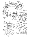
- FIG. 1 An extruded from an aluminum alloy bumper 10 for a not reproduced for reasons of clarity passenger cars has shown in FIG. 1, a box-shaped hollow section 12 with two mutually spaced a profile walls 14, 16, which are connected by two transverse or flank walls 18.
- the hollow section 12 is a - to the indicated at A vehicle longitudinal axis at right angles extending - transverse plane E. assigned as well as on both sides of the here forming a plane of symmetry vehicle longitudinal axis A to the transverse plane E evenly curved out;
- the hollow section 12 determines a curvature k in the longitudinal axis A lying in the curvature center.
- the outer profile wall 14 facing away from the transverse plane E forms an outer or compression belt receiving the impact force, the other inner profile wall 16 an inner or tension belt.
- the bumper 10 is here associated with a pair of vehicle longitudinal members 30, which extend on both sides parallel to the vehicle longitudinal axis A. They are in turn composed of two parallel side walls 34 and these connecting transverse walls 36 which define a recognizable in Fig. 3 interior 32 of the vehicle longitudinal member 30.
- a one-sided mounted in the side member 30 tubular, also made of a extruded from light metal profile element deformation member 40 is indicated as a holder of a profile element, at the other End is defined in a side view wedge-shaped support member 43.
- FIG. 3 Another embodiment of the connection of the hollow profile 12 to the vehicle side member 30 is sketched on the left in Fig. 1 end of the bumper 10 and in Fig. 3. It is clear here that serving as the outer belt, in cross-section wavy shaped profile wall 14 both transverse or flank walls 18 with wing-like wall sections as edge strips 15, 15 t overlaps. FIG. 3 also shows that the side wall 34 of the vehicle longitudinal member 30 likewise projects beyond the outer surface of the attached transverse wall 36 with an edge strip 35. Incidentally, the second side wall 34 is not shown here for reasons of clarity and their attachment area highlighted hatched.
- connection of the hollow profile 12 to the vehicle longitudinal member 30 is here by a from a - extruded in turn from an aluminum alloy - as a hollow profile of width b, for example, 55 mm and the height h of 75 mm designed holding member 46.
- the Vehicle longitudinal members 30 of the profile height e assigned and screwed in this plug-in portion 48 approximately rectangular cross-section - of two parallel side walls 49 and connecting transverse walls 50 of the hollow profile of the holder 46 - includes a curvature section 52; the right in Fig.
- side wall 49 is outwardly - so here from the longitudinal axis M 1 of the plug portion 48 to the right curved and the other side wall 49 endward brought to this so that both side walls 49 lie on each other and each of the two transverse walls 50 approximately in their Longitudinal center is folded.
- the double-layered legs 54 of the trough-like curvature section 52 thus formed are in the range of - not visible in the drawing - breakthroughs of screws 56 or the like. Interspersed through connecting organs, which also engage in bumper-side openings of the flank walls 18. Corresponding openings for connecting members 56 a are provided in the plug portion 48 of the support member 46. These connecting members 56 a store in the vehicle longitudinal member 30 in openings 38th
- the flank walls 18 and the connecting these profile walls 14, 16 of the bumper 11 in Fig. 4, 5 produce a iw square cross section of a hollow section 12 a , the corners of profile beads 17 are determined.
- a profile element 60 tubular shape of the diameter d of a light metal alloy to the tension belt 16 welded to a weld.
- the wall 58 of this profile tube 60 is at a small distance f to the tension belt 16 is provided with a pair of wall apertures 64 each defining an approximately circular edge 66;
- Each wall opening 64 of the deformation member 60 is provided below one of the two lower profile beads 17 of the bumper 11.
- the bumper 11 during an impact - especially in a high-speed impact or a bounce against a standing post - bent by an attacking, for example, in the longitudinal axis A external force P as shown in FIG. 5, the force reaching the deformation element 60 force component by a deformation process compensated at the wall openings 64; the latter are reshaped into circumferential slots 64 z running approximately parallel to the tension belt 16, and the upper weld 62 is not affected as much as a lower weld 62 t which holds the profile element or deformation element 60 on a base plate 68 during a test , which optionally allows a connection with the vehicle longitudinal member 30.
- This bottom plate 68 is attached to a partner by screws 56 b .
- welding rods 74 are assigned to the common diametral D and inclined at that angle w 1 . These welding rods 74 protrude out of the weld 62 t and rest against the outer or surface 59 of the deformation element 60. They connect the latter even in inclined fracture position shown in FIG. 10 after the emergence of the partial gap 72 between the edge 57 of the deformation element 60 and the lower weld 62 t with this.
- the upper weld 62 of the tubular profile element 61 of FIG. 11, 12 connects this also with the tension belt 16 of a bumper 11 a near the end edge 20.
- the bracket or the profile element 61 is in the edge walls 18 of the bumper 11 a respectively one longitudinal - to detect or end slot 76, the length of n 1 is slightly shorter than the diameter d of the profile element 61.
- the longitudinal slit extends over 76, the center line M of the support or of the profile element 61, that is, that the larger part of the cross section of the holder 61 is welded in the vicinity of the longitudinal slots 76 to the tension belt 16.
- this slot area opens like a mouth; the tension belt 16 remains in that length n 1 connected to the profile element 61, and the remaining there upper part of the bumper 11 a folds around the end edge or slot edge 78 of the longitudinal slot 76 down. Also in this embodiment, the welds 62, 62 t are spared.
- Figs. 13, 14 illustrate a further design of a bracket 80 a only sketchily indicated bumper 10 a to an unillustrated vehicle.
- This deformation member 80 approximately square cross-section, whose longitudinal axis is denoted by B, is connected with its bumper 10 a distal end edge 82 to a rear plate 84 of thickness i.
- Their length c and width q or q 1 are greater than the height h and the width b of the support cross-section.
- a lateral Plattenanformung 88 with part-circular, in particular semicircular edge 87 can be seen, which merges from the longitudinal edge 86 and in one of these adjacent transverse edge 89.
- the latter total length q is thus greater than the length q 1 of the other transverse edge 89 a .
- Plattenanformung 88 begins near the longitudinal edge 86 of this parallel adjacent, rising from the surface 85 lateral web 90 of the height h 1 and the axial length z, which corresponds to about twice the height of height h 1 .
- This flank web 90 terminates in each case at an axial distance z 1 to the transverse edges 88, 88 a of the rear plate 84.
- This distance z 1 moreover, also corresponds approximately to half the length z of the flank web 90.
- edge web 90 At the foot edge of the edge web 90 is in the region of the outer surface 92, an inclined, to the longitudinal edge 91 cross-sectional widening skirting 91 of the seat reinforcement formed.
- the distance t of its inner surface 92 from the adjacent longitudinal edge 86 of the rear plate 84 is also better on the other longitudinal edge 86 a indicated; its dimension corresponds approximately to half the distance t 1 of the slots 94 of that longitudinal edge 86 a .
- This rear plate 84 is, as I said, the stop member for a corresponding connection element of the longitudinal beam 30, not shown in Fig. 13, 14 and offers with its - an outer side wall surface 81 of the bracket 80 adjacent - edge web 90 a particularly favorable positional security. Overall, the rear plate 84 forms a endskyrtiges reinforcing member for the connection of the bumper 12 a to the side member 30th
Landscapes
- Engineering & Computer Science (AREA)
- Mechanical Engineering (AREA)
- Body Structure For Vehicles (AREA)
Applications Claiming Priority (1)
| Application Number | Priority Date | Filing Date | Title |
|---|---|---|---|
| DE102006033822 | 2006-07-19 |
Publications (3)
| Publication Number | Publication Date |
|---|---|
| EP1880905A2 true EP1880905A2 (fr) | 2008-01-23 |
| EP1880905A3 EP1880905A3 (fr) | 2009-08-05 |
| EP1880905B1 EP1880905B1 (fr) | 2014-03-12 |
Family
ID=38645903
Family Applications (1)
| Application Number | Title | Priority Date | Filing Date |
|---|---|---|---|
| EP20070014123 Not-in-force EP1880905B1 (fr) | 2006-07-19 | 2007-07-19 | Pare-chocs avec éléments de support |
Country Status (1)
| Country | Link |
|---|---|
| EP (1) | EP1880905B1 (fr) |
Citations (3)
| Publication number | Priority date | Publication date | Assignee | Title |
|---|---|---|---|---|
| US4563028A (en) | 1982-07-01 | 1986-01-07 | Aisin Seiki Kabushiki Kaisha | Reinforcement member for a vehicle bumper |
| US5080410A (en) | 1991-04-22 | 1992-01-14 | Chrysler Corporation | Vehicle bumper beam |
| EP0894675A1 (fr) | 1997-07-28 | 1999-02-03 | Ecia - Equipements Et Composants Pour L'industrie Automobile | Pare-chocs pour véhicule automobile et procédés de fabrication de ce pare-chocs |
Family Cites Families (6)
| Publication number | Priority date | Publication date | Assignee | Title |
|---|---|---|---|---|
| US4190276A (en) * | 1976-12-22 | 1980-02-26 | Mitsubishi Jidosha Kogyo Kabushiki Kaisha | Deformable impact absorbing device for vehicles |
| US5875875A (en) * | 1996-11-05 | 1999-03-02 | Knotts; Stephen Eric | Shock isolator and absorber apparatus |
| US6485072B1 (en) * | 1999-12-15 | 2002-11-26 | Ford Global Technologies, Inc. | Bumper system for motor vehicles |
| US7070217B2 (en) * | 2002-04-19 | 2006-07-04 | Magna International Inc. | Collision energy-absorbing device |
| DE10234253B3 (de) * | 2002-07-27 | 2004-04-08 | Hydro Aluminium Deutschland Gmbh | Crashbox für Kraftfahrzeuge |
| DE102004060088B3 (de) * | 2004-12-13 | 2006-02-16 | Benteler Automobiltechnik Gmbh | Stoßfängeranordnung für ein Kraftfahrzeug |
-
2007
- 2007-07-19 EP EP20070014123 patent/EP1880905B1/fr not_active Not-in-force
Patent Citations (3)
| Publication number | Priority date | Publication date | Assignee | Title |
|---|---|---|---|---|
| US4563028A (en) | 1982-07-01 | 1986-01-07 | Aisin Seiki Kabushiki Kaisha | Reinforcement member for a vehicle bumper |
| US5080410A (en) | 1991-04-22 | 1992-01-14 | Chrysler Corporation | Vehicle bumper beam |
| EP0894675A1 (fr) | 1997-07-28 | 1999-02-03 | Ecia - Equipements Et Composants Pour L'industrie Automobile | Pare-chocs pour véhicule automobile et procédés de fabrication de ce pare-chocs |
Also Published As
| Publication number | Publication date |
|---|---|
| EP1880905A3 (fr) | 2009-08-05 |
| EP1880905B1 (fr) | 2014-03-12 |
Similar Documents
| Publication | Publication Date | Title |
|---|---|---|
| DE102011111644B4 (de) | Lenkstützgliedaufbau | |
| DE102005029738B4 (de) | Energieabsorberelement und dieses verwendende Kraftfahrzeugkarosserie | |
| DE102017123325B4 (de) | Stoßfängerquerträger | |
| DE602005002657T2 (de) | Crashbox für fahrzeug | |
| DE4138647C2 (de) | Rücklehnenrahmen für einen Sitz | |
| DE102007042292B4 (de) | Plastisch verformbare Doppelzellenverbindung für die Front von Automobilen | |
| EP1717107B1 (fr) | Pare-chocs pourvu de supports de fixation | |
| DE102010006977A1 (de) | Kraftfahrzeug-Vorderbau | |
| DE112010006033T5 (de) | Fahrzeugstossfängerträger und Verfahren zur Herstellung desselben | |
| DE202007019296U1 (de) | Anordnung zum Befestigen einer Stoßstange an Längsträgern eines Fahrzeuges | |
| DE102018119735A1 (de) | Stoßfängerquerträger für ein Kraftfahrzeug | |
| DE102017008204A1 (de) | Rückwärtige Fahrzeugkarosseriestruktur eines Fahrzeugs und Verfahren zum Herstellen desselben | |
| DE102012005561A1 (de) | Hilfsrahmen für ein Kraftfahrzeug | |
| DE10009363A1 (de) | Kotflügelanordnung für ein Kraftfahrzeug | |
| DE102008029634A1 (de) | Stoßfänger mit Halterungen für ein Fahrzeug | |
| DE19603954C2 (de) | Prallträger für ein Kraftfahrzeug | |
| DE102016216803A1 (de) | Stabilisator-stützstruktur | |
| DE4428101C2 (de) | Rahmenkopf für einen Tragrahmen eines Lastkraftwagens | |
| EP2730457B1 (fr) | Entraînement d'un dispositif de réglage de siège pour véhicules automobiles | |
| DE102014008712B4 (de) | Fahrzeugfrontstruktur | |
| DE102007033764A1 (de) | Stoßstange mit Halterungen | |
| DE102006019653B4 (de) | Stoßstange mit Halterungen | |
| EP1880905B1 (fr) | Pare-chocs avec éléments de support | |
| DE602004001594T2 (de) | Verbindungsstruktur einer Motorhaubenschlosshalterung | |
| DE102004046585B4 (de) | Stoßfängervorrichtung |
Legal Events
| Date | Code | Title | Description |
|---|---|---|---|
| PUAI | Public reference made under article 153(3) epc to a published international application that has entered the european phase |
Free format text: ORIGINAL CODE: 0009012 |
|
| AK | Designated contracting states |
Kind code of ref document: A2 Designated state(s): AT BE BG CH CY CZ DE DK EE ES FI FR GB GR HU IE IS IT LI LT LU LV MC MT NL PL PT RO SE SI SK TR |
|
| AX | Request for extension of the european patent |
Extension state: AL BA HR MK YU |
|
| PUAL | Search report despatched |
Free format text: ORIGINAL CODE: 0009013 |
|
| AK | Designated contracting states |
Kind code of ref document: A3 Designated state(s): AT BE BG CH CY CZ DE DK EE ES FI FR GB GR HU IE IS IT LI LT LU LV MC MT NL PL PT RO SE SI SK TR |
|
| AX | Request for extension of the european patent |
Extension state: AL BA HR MK RS |
|
| 17P | Request for examination filed |
Effective date: 20091125 |
|
| 17Q | First examination report despatched |
Effective date: 20100108 |
|
| AKX | Designation fees paid |
Designated state(s): AT BE BG CH CY CZ DE DK EE ES FI FR GB GR HU IE IS IT LI LT LU LV MC MT NL PL PT RO SE SI SK TR |
|
| RAP1 | Party data changed (applicant data changed or rights of an application transferred) |
Owner name: 3A TECHNOLOGY & MANAGEMENT AG |
|
| RAP1 | Party data changed (applicant data changed or rights of an application transferred) |
Owner name: ENGINEERED PRODUCTS SWITZERLAND AG (LTD.) |
|
| RAP1 | Party data changed (applicant data changed or rights of an application transferred) |
Owner name: CONSTELLIUM SWITZERLAND AG |
|
| GRAP | Despatch of communication of intention to grant a patent |
Free format text: ORIGINAL CODE: EPIDOSNIGR1 |
|
| INTG | Intention to grant announced |
Effective date: 20131128 |
|
| GRAS | Grant fee paid |
Free format text: ORIGINAL CODE: EPIDOSNIGR3 |
|
| GRAA | (expected) grant |
Free format text: ORIGINAL CODE: 0009210 |
|
| AK | Designated contracting states |
Kind code of ref document: B1 Designated state(s): AT BE BG CH CY CZ DE DK EE ES FI FR GB GR HU IE IS IT LI LT LU LV MC MT NL PL PT RO SE SI SK TR |
|
| REG | Reference to a national code |
Ref country code: GB Ref legal event code: FG4D Free format text: NOT ENGLISH |
|
| REG | Reference to a national code |
Ref country code: CH Ref legal event code: EP |
|
| REG | Reference to a national code |
Ref country code: AT Ref legal event code: REF Ref document number: 656052 Country of ref document: AT Kind code of ref document: T Effective date: 20140315 |
|
| REG | Reference to a national code |
Ref country code: IE Ref legal event code: FG4D Free format text: LANGUAGE OF EP DOCUMENT: GERMAN |
|
| REG | Reference to a national code |
Ref country code: DE Ref legal event code: R096 Ref document number: 502007012842 Country of ref document: DE Effective date: 20140424 |
|
| REG | Reference to a national code |
Ref country code: NL Ref legal event code: VDEP Effective date: 20140312 |
|
| PG25 | Lapsed in a contracting state [announced via postgrant information from national office to epo] |
Ref country code: LT Free format text: LAPSE BECAUSE OF FAILURE TO SUBMIT A TRANSLATION OF THE DESCRIPTION OR TO PAY THE FEE WITHIN THE PRESCRIBED TIME-LIMIT Effective date: 20140312 |
|
| REG | Reference to a national code |
Ref country code: LT Ref legal event code: MG4D |
|
| PG25 | Lapsed in a contracting state [announced via postgrant information from national office to epo] |
Ref country code: SE Free format text: LAPSE BECAUSE OF FAILURE TO SUBMIT A TRANSLATION OF THE DESCRIPTION OR TO PAY THE FEE WITHIN THE PRESCRIBED TIME-LIMIT Effective date: 20140312 Ref country code: FI Free format text: LAPSE BECAUSE OF FAILURE TO SUBMIT A TRANSLATION OF THE DESCRIPTION OR TO PAY THE FEE WITHIN THE PRESCRIBED TIME-LIMIT Effective date: 20140312 Ref country code: CY Free format text: LAPSE BECAUSE OF FAILURE TO SUBMIT A TRANSLATION OF THE DESCRIPTION OR TO PAY THE FEE WITHIN THE PRESCRIBED TIME-LIMIT Effective date: 20140312 |
|
| PG25 | Lapsed in a contracting state [announced via postgrant information from national office to epo] |
Ref country code: LV Free format text: LAPSE BECAUSE OF FAILURE TO SUBMIT A TRANSLATION OF THE DESCRIPTION OR TO PAY THE FEE WITHIN THE PRESCRIBED TIME-LIMIT Effective date: 20140312 |
|
| PG25 | Lapsed in a contracting state [announced via postgrant information from national office to epo] |
Ref country code: EE Free format text: LAPSE BECAUSE OF FAILURE TO SUBMIT A TRANSLATION OF THE DESCRIPTION OR TO PAY THE FEE WITHIN THE PRESCRIBED TIME-LIMIT Effective date: 20140312 Ref country code: RO Free format text: LAPSE BECAUSE OF FAILURE TO SUBMIT A TRANSLATION OF THE DESCRIPTION OR TO PAY THE FEE WITHIN THE PRESCRIBED TIME-LIMIT Effective date: 20140312 Ref country code: BG Free format text: LAPSE BECAUSE OF FAILURE TO SUBMIT A TRANSLATION OF THE DESCRIPTION OR TO PAY THE FEE WITHIN THE PRESCRIBED TIME-LIMIT Effective date: 20140612 Ref country code: NL Free format text: LAPSE BECAUSE OF FAILURE TO SUBMIT A TRANSLATION OF THE DESCRIPTION OR TO PAY THE FEE WITHIN THE PRESCRIBED TIME-LIMIT Effective date: 20140312 Ref country code: IS Free format text: LAPSE BECAUSE OF FAILURE TO SUBMIT A TRANSLATION OF THE DESCRIPTION OR TO PAY THE FEE WITHIN THE PRESCRIBED TIME-LIMIT Effective date: 20140712 |
|
| PG25 | Lapsed in a contracting state [announced via postgrant information from national office to epo] |
Ref country code: SK Free format text: LAPSE BECAUSE OF FAILURE TO SUBMIT A TRANSLATION OF THE DESCRIPTION OR TO PAY THE FEE WITHIN THE PRESCRIBED TIME-LIMIT Effective date: 20140312 Ref country code: ES Free format text: LAPSE BECAUSE OF FAILURE TO SUBMIT A TRANSLATION OF THE DESCRIPTION OR TO PAY THE FEE WITHIN THE PRESCRIBED TIME-LIMIT Effective date: 20140312 Ref country code: PL Free format text: LAPSE BECAUSE OF FAILURE TO SUBMIT A TRANSLATION OF THE DESCRIPTION OR TO PAY THE FEE WITHIN THE PRESCRIBED TIME-LIMIT Effective date: 20140312 |
|
| REG | Reference to a national code |
Ref country code: DE Ref legal event code: R097 Ref document number: 502007012842 Country of ref document: DE |
|
| PG25 | Lapsed in a contracting state [announced via postgrant information from national office to epo] |
Ref country code: PT Free format text: LAPSE BECAUSE OF FAILURE TO SUBMIT A TRANSLATION OF THE DESCRIPTION OR TO PAY THE FEE WITHIN THE PRESCRIBED TIME-LIMIT Effective date: 20140714 |
|
| PLBE | No opposition filed within time limit |
Free format text: ORIGINAL CODE: 0009261 |
|
| STAA | Information on the status of an ep patent application or granted ep patent |
Free format text: STATUS: NO OPPOSITION FILED WITHIN TIME LIMIT |
|
| PG25 | Lapsed in a contracting state [announced via postgrant information from national office to epo] |
Ref country code: DK Free format text: LAPSE BECAUSE OF FAILURE TO SUBMIT A TRANSLATION OF THE DESCRIPTION OR TO PAY THE FEE WITHIN THE PRESCRIBED TIME-LIMIT Effective date: 20140312 |
|
| 26N | No opposition filed |
Effective date: 20141215 |
|
| PG25 | Lapsed in a contracting state [announced via postgrant information from national office to epo] |
Ref country code: LU Free format text: LAPSE BECAUSE OF FAILURE TO SUBMIT A TRANSLATION OF THE DESCRIPTION OR TO PAY THE FEE WITHIN THE PRESCRIBED TIME-LIMIT Effective date: 20140719 |
|
| REG | Reference to a national code |
Ref country code: CH Ref legal event code: PL |
|
| REG | Reference to a national code |
Ref country code: DE Ref legal event code: R097 Ref document number: 502007012842 Country of ref document: DE Effective date: 20141215 |
|
| PG25 | Lapsed in a contracting state [announced via postgrant information from national office to epo] |
Ref country code: IT Free format text: LAPSE BECAUSE OF FAILURE TO SUBMIT A TRANSLATION OF THE DESCRIPTION OR TO PAY THE FEE WITHIN THE PRESCRIBED TIME-LIMIT Effective date: 20140312 |
|
| REG | Reference to a national code |
Ref country code: IE Ref legal event code: MM4A |
|
| PG25 | Lapsed in a contracting state [announced via postgrant information from national office to epo] |
Ref country code: CH Free format text: LAPSE BECAUSE OF NON-PAYMENT OF DUE FEES Effective date: 20140731 Ref country code: LI Free format text: LAPSE BECAUSE OF NON-PAYMENT OF DUE FEES Effective date: 20140731 |
|
| REG | Reference to a national code |
Ref country code: FR Ref legal event code: PLFP Year of fee payment: 9 |
|
| PG25 | Lapsed in a contracting state [announced via postgrant information from national office to epo] |
Ref country code: SI Free format text: LAPSE BECAUSE OF FAILURE TO SUBMIT A TRANSLATION OF THE DESCRIPTION OR TO PAY THE FEE WITHIN THE PRESCRIBED TIME-LIMIT Effective date: 20140312 |
|
| PG25 | Lapsed in a contracting state [announced via postgrant information from national office to epo] |
Ref country code: IE Free format text: LAPSE BECAUSE OF NON-PAYMENT OF DUE FEES Effective date: 20140719 |
|
| REG | Reference to a national code |
Ref country code: AT Ref legal event code: MM01 Ref document number: 656052 Country of ref document: AT Kind code of ref document: T Effective date: 20140719 |
|
| PG25 | Lapsed in a contracting state [announced via postgrant information from national office to epo] |
Ref country code: AT Free format text: LAPSE BECAUSE OF NON-PAYMENT OF DUE FEES Effective date: 20140719 |
|
| PG25 | Lapsed in a contracting state [announced via postgrant information from national office to epo] |
Ref country code: MC Free format text: LAPSE BECAUSE OF FAILURE TO SUBMIT A TRANSLATION OF THE DESCRIPTION OR TO PAY THE FEE WITHIN THE PRESCRIBED TIME-LIMIT Effective date: 20140312 |
|
| PG25 | Lapsed in a contracting state [announced via postgrant information from national office to epo] |
Ref country code: GR Free format text: LAPSE BECAUSE OF FAILURE TO SUBMIT A TRANSLATION OF THE DESCRIPTION OR TO PAY THE FEE WITHIN THE PRESCRIBED TIME-LIMIT Effective date: 20140613 Ref country code: MT Free format text: LAPSE BECAUSE OF FAILURE TO SUBMIT A TRANSLATION OF THE DESCRIPTION OR TO PAY THE FEE WITHIN THE PRESCRIBED TIME-LIMIT Effective date: 20140312 |
|
| REG | Reference to a national code |
Ref country code: FR Ref legal event code: PLFP Year of fee payment: 10 |
|
| PG25 | Lapsed in a contracting state [announced via postgrant information from national office to epo] |
Ref country code: TR Free format text: LAPSE BECAUSE OF FAILURE TO SUBMIT A TRANSLATION OF THE DESCRIPTION OR TO PAY THE FEE WITHIN THE PRESCRIBED TIME-LIMIT Effective date: 20140312 Ref country code: HU Free format text: LAPSE BECAUSE OF FAILURE TO SUBMIT A TRANSLATION OF THE DESCRIPTION OR TO PAY THE FEE WITHIN THE PRESCRIBED TIME-LIMIT; INVALID AB INITIO Effective date: 20070719 Ref country code: BE Free format text: LAPSE BECAUSE OF FAILURE TO SUBMIT A TRANSLATION OF THE DESCRIPTION OR TO PAY THE FEE WITHIN THE PRESCRIBED TIME-LIMIT Effective date: 20140731 |
|
| REG | Reference to a national code |
Ref country code: FR Ref legal event code: PLFP Year of fee payment: 11 |
|
| REG | Reference to a national code |
Ref country code: FR Ref legal event code: PLFP Year of fee payment: 12 |
|
| PGFP | Annual fee paid to national office [announced via postgrant information from national office to epo] |
Ref country code: CZ Payment date: 20210712 Year of fee payment: 15 Ref country code: FR Payment date: 20210726 Year of fee payment: 15 |
|
| PGFP | Annual fee paid to national office [announced via postgrant information from national office to epo] |
Ref country code: DE Payment date: 20210728 Year of fee payment: 15 Ref country code: GB Payment date: 20210727 Year of fee payment: 15 |
|
| REG | Reference to a national code |
Ref country code: DE Ref legal event code: R119 Ref document number: 502007012842 Country of ref document: DE |
|
| GBPC | Gb: european patent ceased through non-payment of renewal fee |
Effective date: 20220719 |
|
| PG25 | Lapsed in a contracting state [announced via postgrant information from national office to epo] |
Ref country code: FR Free format text: LAPSE BECAUSE OF NON-PAYMENT OF DUE FEES Effective date: 20220731 Ref country code: CZ Free format text: LAPSE BECAUSE OF NON-PAYMENT OF DUE FEES Effective date: 20220719 |
|
| PG25 | Lapsed in a contracting state [announced via postgrant information from national office to epo] |
Ref country code: GB Free format text: LAPSE BECAUSE OF NON-PAYMENT OF DUE FEES Effective date: 20220719 Ref country code: DE Free format text: LAPSE BECAUSE OF NON-PAYMENT OF DUE FEES Effective date: 20230201 |
|
| P01 | Opt-out of the competence of the unified patent court (upc) registered |
Effective date: 20230411 |