EP1880916A2 - Kinderwagen mit Klappvorrichtung am Schiebergriff - Google Patents
Kinderwagen mit Klappvorrichtung am Schiebergriff Download PDFInfo
- Publication number
- EP1880916A2 EP1880916A2 EP07112595A EP07112595A EP1880916A2 EP 1880916 A2 EP1880916 A2 EP 1880916A2 EP 07112595 A EP07112595 A EP 07112595A EP 07112595 A EP07112595 A EP 07112595A EP 1880916 A2 EP1880916 A2 EP 1880916A2
- Authority
- EP
- European Patent Office
- Prior art keywords
- handlebar
- unlocking
- stroller
- range
- stroller according
- Prior art date
- Legal status (The legal status is an assumption and is not a legal conclusion. Google has not performed a legal analysis and makes no representation as to the accuracy of the status listed.)
- Withdrawn
Links
Images

Classifications
-
- B—PERFORMING OPERATIONS; TRANSPORTING
- B62—LAND VEHICLES FOR TRAVELLING OTHERWISE THAN ON RAILS
- B62B—HAND-PROPELLED VEHICLES, e.g. HAND CARTS OR PERAMBULATORS; SLEDGES
- B62B7/00—Carriages for children; Perambulators, e.g. dolls' perambulators
- B62B7/04—Carriages for children; Perambulators, e.g. dolls' perambulators having more than one wheel axis; Steering devices therefor
- B62B7/06—Carriages for children; Perambulators, e.g. dolls' perambulators having more than one wheel axis; Steering devices therefor collapsible or foldable
- B62B7/08—Carriages for children; Perambulators, e.g. dolls' perambulators having more than one wheel axis; Steering devices therefor collapsible or foldable in the direction of, or at right angles to, the wheel axis
-
- B—PERFORMING OPERATIONS; TRANSPORTING
- B62—LAND VEHICLES FOR TRAVELLING OTHERWISE THAN ON RAILS
- B62B—HAND-PROPELLED VEHICLES, e.g. HAND CARTS OR PERAMBULATORS; SLEDGES
- B62B9/00—Accessories or details specially adapted for children's carriages or perambulators
- B62B9/20—Handle bars; Handles
-
- B—PERFORMING OPERATIONS; TRANSPORTING
- B62—LAND VEHICLES FOR TRAVELLING OTHERWISE THAN ON RAILS
- B62B—HAND-PROPELLED VEHICLES, e.g. HAND CARTS OR PERAMBULATORS; SLEDGES
- B62B2205/00—Hand-propelled vehicles or sledges being foldable or dismountable when not in use
- B62B2205/02—Hand-propelled vehicles or sledges being foldable or dismountable when not in use foldable widthwise
-
- B—PERFORMING OPERATIONS; TRANSPORTING
- B62—LAND VEHICLES FOR TRAVELLING OTHERWISE THAN ON RAILS
- B62B—HAND-PROPELLED VEHICLES, e.g. HAND CARTS OR PERAMBULATORS; SLEDGES
- B62B2205/00—Hand-propelled vehicles or sledges being foldable or dismountable when not in use
- B62B2205/18—Geared articulations
-
- B—PERFORMING OPERATIONS; TRANSPORTING
- B62—LAND VEHICLES FOR TRAVELLING OTHERWISE THAN ON RAILS
- B62B—HAND-PROPELLED VEHICLES, e.g. HAND CARTS OR PERAMBULATORS; SLEDGES
- B62B2205/00—Hand-propelled vehicles or sledges being foldable or dismountable when not in use
- B62B2205/20—Catches; Locking or releasing an articulation
- B62B2205/22—Catches; Locking or releasing an articulation remotely controlled, e.g. from the handlebar
Definitions
- the field of the invention is that of childcare. More specifically, the invention relates to strollers for children.
- the strollers for children generally comprise push arms allowing them to be pushed by an adult.
- the upper end of these push arms can be constituted, according to the stroller models, by handles or by a handlebar connecting the push arms.
- the present invention relates more particularly to strollers comprising a handlebar connecting the push arms.
- the height of the handlebar of the strollers is sometimes adjustable in height. This adjustment can for example be done in the case of handlebars having a U-shape, changing the angle formed by the handlebar and the push arms.
- the handlebar can take several positions of use.
- the release controls of the structure of the stroller are accessible when the user is in the driving position of the stroller.
- These controls are therefore commonly installed on or near the handles or handlebars of the stroller.
- the unlocking controls are double, to prevent unintentional unlocking of the stroller.
- These are usually two buttons that must be operated successively by the user, one hand, or two buttons to be operated simultaneously.
- the document EP0989043 shows an example of a stroller with a handlebar whose angular position is adjustable, and carrying the stroller unlocking controls.
- unlocking command is quite difficult to operate for the user. Indeed, for security reasons, the unlocking can not be operated by a single button. It is therefore necessary to have a set of two buttons, which must be operated with one hand.
- such a folding mechanism fits a folding stroller "flat", but it is more difficult to implement on a three-dimensional folding stroller.
- the handlebar of such a stroller must be able to be folded, and it is not easy to implement on a folding handlebars a double folding control.
- Such a stroller becomes difficult to handle by an unsuspecting user. Indeed, it has a large number of different commands to control the inclination of the handlebar, the folding and, depending on the case, the locking of the directional wheels or the attachment of the seats or accessories ... The use of such strollers so is not obvious to the user.
- the invention particularly aims to overcome these disadvantages of the prior art.
- an object of the invention is to provide a stroller with a particularly reliable folding mechanism, and which, in particular, does not present a risk of inadvertent or inadvertent folding
- Another object of the invention is to provide such a stroller that is particularly easy to fold and unfold by the user, even unaccustomed to its use.
- the invention also aims to provide such a stroller which, in the folded position, is particularly compact.
- Such a stroller is reliable, easy to use and has fewer controls, which makes it easier for the user.
- the handlebar is movable in rotation relative to the frame.
- the intermediate range prevents the user from unlocking the stroller accidentally, wanting to adjust the height of the handlebars.
- the handlebar acts on at least one cable connected to at least one of the unlocking elements.
- the handlebar acts on the cable via a cable boarding rod which is rotated by the handlebar in the unlocking zone.
- the joint cooperates with a control button for locking in rotation of the handlebars in certain predetermined positions.
- the locking in rotation of the handlebar is only possible when it is in the range of driving position adjustment.
- the unlocking element of the frame allows initiation of the folding of the frame, a complementary action on at least one other unlocking element being necessary to obtain the complete folding.
- This two-step unlocking mode meets the requirements of current standards.
- the chassis unlocking element produces an audible signal when it goes into the unlocked position.
- This signal allows the user to be informed that the frame of the stroller is unlocked.
- the general principle of the invention is based on the articulated handlebar of the stroller which can, on the one hand, lock in several positions of use and, on the other hand, be brought into a position in which it causes the unlocking of the structure of the stroller.
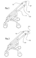
- FIG. 1 shows a stroller according to one embodiment of the invention.
- This stroller comprises in particular two push arms 11 at the upper end of which is a handlebar 12.
- the stroller is designed to be foldable in three dimensions, so that its push arms, when it and folded, are brought closer together. the other.
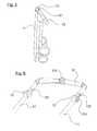
- the stroller is shown in the folded position in FIG. 5. In this position, the handlebar is deformed with respect to its position of use, so as to allow the right and left parts of the stroller to approach one of the other.
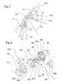
- the handlebar 12 is shown in more detail in FIG. 6. It is articulated, and comprises a central articulation 121 and two lateral joints 122. It is also possible to modify the angle formed by the handlebar 12 with the uprights 11, when the stroller is deployed, by rotation around two adjusting nuts 13, located at the junction of the push arms 11 and the handlebar 12.
- Each of the adjusting nuts 13 comprises a control button 131 for unlocking the handlebar.
- the position of the handlebar relative to the push arm is locked by a locking mechanism included in the adjusting nuts 13.
- a pressure of the user on the two unlocking control buttons 131 allows unlocking this position, which allows the user to change the handlebar height.
- the user has brought the handlebars into an adjustment position that suits him, he releases the unlocking control buttons 131, and the handlebar position is locked.
- Figures 1 and 2 thus represent two possible use positions of the handlebar 12 of the stroller.
- the illustrated stroller allows four positions of use of the handlebar, which are shown under the numbers 711, 712, 713 and 714 in Figure 7. These four positions are included in an angular range of pipe 71, which goes from the position in which the handlebar is in the extension of the push arm 11 (position 711, shown in Figure 1) at a position 714 in which the handlebar is lower than the horizontal position.
- a return spring 87 acts on the handlebar 12 and tends to return it to the unlocking guard position.
- the handlebar return spring 87 returns the handlebar 12 to its unlocking guard position.
- the handlebars do not interfere with the folding, regardless of the installation position of the hammock fixed on the chassis, facing road or back to the road, and whatever the tilting position of this hammock.
- the stroller shown in Figure 5 and the handlebar 741 of Figure 7 thus correspond to the folded position of the stroller.
- the adjusting nut 13 therefore comprises the elements allowing both the height adjustment of the handlebar and the unlocking of the frame of the stroller.
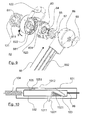
- the elements constituting one of these nuts are shown exploded in Figures 8 and 9.
- the nut is composed of a half-nut 82 linked to the handlebar and a half-nut 88 connected to the pusher.
- the half-nut 82 carries the unlocking control knob 131 and the half-nut 88 carries a basket holder 89.
- Between the two half-nuts are a toothed wheel 83, a return spring of the button 84, a cable boarding rod 85, to which is connected the frame release cable 86, and a handlebar return spring 87.
- the half-nut 82, the toothed wheel 83, the return spring 84, the connecting rod 85, and the return spring 87 are pivotally mounted on a shaft 883 which is connected to the half-nut 88.
- the shaft 883 has a shoulder 884.
- the inner diameter of the return spring of the handlebar 87 and that of the connecting rod 85 correspond to the largest diameter of the shaft 883.
- a washer (Not shown) of internal diameter adapted to the smallest diameter of the shaft 883 bears on this shoulder of the shaft 883.
- the return spring of the button 84 is mounted in abutment on this washer.
- the half-nut 82 is connected to the handlebar via the lateral articulation 122. It has on its inner face of the teeth 821 complementary to those of the toothed wheel 83.
- the half-nut is connected to the push arm 11 via the slide 881, which is inserted into the tube forming the push arm. It also has on its inner face of the teeth 881 complementary to those of the toothed wheel 83.
- the button 131 can slide in the half-nut 82. It comprises support rods 811 which can slide in corresponding holes 824 of the half-nut 82. These support rods 811, when the button 81 is actuated, shift the toothed wheel 83, compressing the return spring of the button 84, until the toothed wheel 83 is no longer engaged with the teeth 821 of the half-nut 82. At this moment, the half-nut 82 is free to rotate relative to the half-nut 88 and the toothed wheel
- the half-nut 82 carries a finger 823 which, in the positions of use of the stroller, is housed in the groove 833 of the toothed wheel 83.
- the action of this finger 833 on the toothed wheel prevents the rotation of the half 82, beyond the position represented by FIG. 1, in a direction other than that represented by the arrow 9 of FIG. 9.
- the inside of the half-nut 82 includes a toothed zone 822. As long as the handlebar 12 is in a position corresponding to the angular range of pipe 71, this toothless zone is opposite an empty zone 831 of the gear 83. the presence of this toothless zone 822 and this empty zone 831 does not prevent the toothed wheel 83 from coming into engagement with the half-nut 82 when the user releases the button 131. The position of the handlebar can therefore lock in these positions.
- this toothless zone is opposite the teeth of the toothed wheel 83. no longer engage with the half-nut 82, even if the user releases the button 131. It is therefore impossible to lock the position of the handlebar 12 in these angular areas.
- the connecting rod of the cable includes a head 851 which is placed in the empty zone 831 of the toothed wheel 83, this head 851 is held by the return spring 87, which acts in torsion, against the wall 832 of the empty zone 831 .
- FIG. 10 One possible embodiment of the unlocking mechanism is shown diagrammatically in FIG. 10.
- This figure shows a fixed support 101 which is situated inside the tube forming the push arm 11, and which is fixed to this tube.
- a spring blade 103 is fixed at one of its ends to the fixed support 101. At its other end, it carries a locking pin 1031. This locking pin, in the locked position of the stroller, partially leaves the fixed support through the opening 1011 to ensure the attachment of the push arm 11 with the front stretcher of the stroller.
- a shuttle 102 is slidably mounted in the fixed support 101. It is held, by one of its ends, by a spring 104 which is fixed to the tube forming the push arm 11, and by the other of its ends to the cable 86 The sliding of this shuttle 102 is therefore controlled by the unlocking commands.
- the shuttle 102 has a slope to act on the spring blade 103. Thus, when traction is exerted on the cable 86, the shuttle 102 moves to the right and the slope deforms the spring blade 103 until the pin 1031 retracts completely into the fixed support 101.
- a second leaf spring 105 is fixed, by one of its ends, to the shuttle 102. It carries at its other end a button 1051, which is held against the wall of the fixed support 101.
- the button 1051 enters the opening 1012 of the fixed support, making a slight noise ("click"). This "click" allows to return to the user the information that the unlocking of the chassis is effective.
- a holding system which may be internal or external to the adjusting nuts 13, keeps the handlebar in the folding position shown in Figure 5, wherein the handlebar is inclined at most with respect to the push arm. This position allows a better compactness of the folded stroller.
- the nut 13 is closed by a not shown screw which passes inside the shaft 883 and is screwed into the basket hook 9, which comprises a nut.
- the head of the screw is hidden under the control knob 131.
- Unlocking the structure of the stroller following an action on the handlebars can allow the total folding of the stroller. According to another embodiment, this unlocking allows only one initiation of folding, which must be continued by actuating another unlocking means. Such a mode of folding is described by the patent application FR0307581 , in the name of the plaintiff.
Landscapes
- Engineering & Computer Science (AREA)
- Chemical & Material Sciences (AREA)
- Combustion & Propulsion (AREA)
- Transportation (AREA)
- Mechanical Engineering (AREA)
- Health & Medical Sciences (AREA)
- Public Health (AREA)
- Carriages For Children, Sleds, And Other Hand-Operated Vehicles (AREA)
Applications Claiming Priority (1)
| Application Number | Priority Date | Filing Date | Title |
|---|---|---|---|
| FR0606488A FR2903641A1 (fr) | 2006-07-17 | 2006-07-17 | Poussette a commande de pliage au guidon. |
Publications (2)
| Publication Number | Publication Date |
|---|---|
| EP1880916A2 true EP1880916A2 (de) | 2008-01-23 |
| EP1880916A3 EP1880916A3 (de) | 2008-09-17 |
Family
ID=37751944
Family Applications (1)
| Application Number | Title | Priority Date | Filing Date |
|---|---|---|---|
| EP07112595A Withdrawn EP1880916A3 (de) | 2006-07-17 | 2007-07-17 | Kinderwagen mit Klappvorrichtung am Schiebergriff |
Country Status (2)
| Country | Link |
|---|---|
| EP (1) | EP1880916A3 (de) |
| FR (1) | FR2903641A1 (de) |
Cited By (7)
| Publication number | Priority date | Publication date | Assignee | Title |
|---|---|---|---|---|
| GB2507507A (en) * | 2012-10-31 | 2014-05-07 | Russell Anthony Clifton | A ratchet and pawl mechanism for the folding handle of a stroller |
| CN106741100A (zh) * | 2016-11-28 | 2017-05-31 | 浙江晨辉婴宝儿童用品有限公司 | 一种改进后脚杆的折叠车架 |
| CN108784136A (zh) * | 2017-05-02 | 2018-11-13 | 广东奥迪动漫玩具有限公司 | 婴幼儿支撑装置 |
| CN108966843A (zh) * | 2018-08-13 | 2018-12-11 | 浙江亚特电器有限公司 | 一种割草机 |
| CN111252129A (zh) * | 2018-12-03 | 2020-06-09 | 环玮健康科技国际企业股份有限公司 | 可由折叠扶手操控车架收合的推车 |
| CN116353678A (zh) * | 2023-04-19 | 2023-06-30 | 安徽酷豆丁科技发展股份有限公司 | 一种折叠婴儿车折叠解锁结构 |
| EP4737268A3 (de) * | 2020-05-29 | 2026-08-05 | Wonderland Switzerland AG | Umwandelbares kinderwagensystem mit zusatzkorb |
Families Citing this family (1)
| Publication number | Priority date | Publication date | Assignee | Title |
|---|---|---|---|---|
| CN110329334B (zh) * | 2019-06-12 | 2024-08-16 | 徐江林 | 一种折叠童车 |
Family Cites Families (4)
| Publication number | Priority date | Publication date | Assignee | Title |
|---|---|---|---|---|
| US5257799A (en) * | 1991-10-04 | 1993-11-02 | Cosco, Inc. | Foldable stroller |
| US5863061A (en) * | 1996-10-25 | 1999-01-26 | Ziegler; Scott William | Collapsible three wheeled stroller |
| DE20011187U1 (de) * | 2000-07-03 | 2000-10-12 | Lan, Red, Hsichih, Taipeh | Zusammenklappbares Fahrgestell |
| NL1018648C2 (nl) * | 2001-07-27 | 2003-02-03 | All Our Kids Europ B V | Kinderwagen. |
-
2006
- 2006-07-17 FR FR0606488A patent/FR2903641A1/fr active Pending
-
2007
- 2007-07-17 EP EP07112595A patent/EP1880916A3/de not_active Withdrawn
Cited By (9)
| Publication number | Priority date | Publication date | Assignee | Title |
|---|---|---|---|---|
| GB2507507A (en) * | 2012-10-31 | 2014-05-07 | Russell Anthony Clifton | A ratchet and pawl mechanism for the folding handle of a stroller |
| CN106741100A (zh) * | 2016-11-28 | 2017-05-31 | 浙江晨辉婴宝儿童用品有限公司 | 一种改进后脚杆的折叠车架 |
| CN108784136A (zh) * | 2017-05-02 | 2018-11-13 | 广东奥迪动漫玩具有限公司 | 婴幼儿支撑装置 |
| CN108784136B (zh) * | 2017-05-02 | 2024-02-13 | 广东奥迪动漫玩具有限公司 | 婴幼儿支撑装置 |
| CN108966843A (zh) * | 2018-08-13 | 2018-12-11 | 浙江亚特电器有限公司 | 一种割草机 |
| CN108966843B (zh) * | 2018-08-13 | 2023-10-13 | 浙江亚特电器股份有限公司 | 一种割草机 |
| CN111252129A (zh) * | 2018-12-03 | 2020-06-09 | 环玮健康科技国际企业股份有限公司 | 可由折叠扶手操控车架收合的推车 |
| EP4737268A3 (de) * | 2020-05-29 | 2026-08-05 | Wonderland Switzerland AG | Umwandelbares kinderwagensystem mit zusatzkorb |
| CN116353678A (zh) * | 2023-04-19 | 2023-06-30 | 安徽酷豆丁科技发展股份有限公司 | 一种折叠婴儿车折叠解锁结构 |
Also Published As
| Publication number | Publication date |
|---|---|
| EP1880916A3 (de) | 2008-09-17 |
| FR2903641A1 (fr) | 2008-01-18 |
Similar Documents
| Publication | Publication Date | Title |
|---|---|---|
| EP2295287B1 (de) | Befestigungsbasis für einen Autokindersitz | |
| FR2602442A1 (fr) | Coupe-cable a main | |
| FR2822419A1 (fr) | Siege de vehicule equipe d'un mecanisme d'articulation | |
| FR2825955A1 (fr) | Mecanisme d'articulation de siege de vehicule ameliore | |
| FR2849089A1 (fr) | Appareil a verrou de couvercle de boite a gants | |
| WO2012085469A1 (fr) | Siège escamotable pour un véhicule automobile | |
| BE737869A (de) | ||
| EP1169955A1 (de) | Deckelverriegelungsvorrichtung | |
| FR2829439A1 (fr) | Pietement de siege de vehicule, siege comportant un tel pietement et ensemble d'assise comportant un tel siege | |
| EP2689995A1 (de) | Verriegelungsmechanismus eines zusammenklappbaren Fahrradlenkers | |
| FR2921024A1 (fr) | Dispositif de maintien de deverrouillage de l'articulation pour siege inclinable de vehicule | |
| FR2515128A1 (fr) | Mecanisme de changement du sens d'orientation des poignees de pousse d'une poussette de bebe et poussette equipee d'un tel mecanisme | |
| FR2903641A1 (fr) | Poussette a commande de pliage au guidon. | |
| FR2893560A1 (fr) | Vehicule comprenant un siege coulissant escamotable | |
| EP0373081B1 (de) | Klappbarer Sitz, insbesondere für die Ausrüstung von Kraftfahrzeugen | |
| EP3353038B1 (de) | Klappgriff für einen kinderwagen | |
| FR2811947A1 (fr) | Siege de vehicule equipe d'un mecanisme d'articulation | |
| FR2840267A1 (fr) | Siege de vehicule | |
| WO2013160433A1 (fr) | Chassis pliable de poussette canne pour enfant. | |
| FR2882625A1 (fr) | Taille-haie equipe d'une partie arriere pivotante | |
| EP1447302A2 (de) | Kinderwagen mit Schieberrahmen mit Schwenkgriffen und korrespondierender Griff | |
| FR2786748A1 (fr) | Systeme de pliage de poussette pour bebes | |
| EP0955000A1 (de) | Verstellvorrichtung für die Neigung eines Kinderstuhls, und ähnlicher Stuhl | |
| FR2806360A1 (fr) | Dispositif de verrouillage d'une jambe de force d'un siege de vehicule automobile | |
| FR2856366A1 (fr) | Voiture d'enfant a chassis pliant comprenant deux moyens de verrouillage pliage, distincts, et chassis correspondant |
Legal Events
| Date | Code | Title | Description |
|---|---|---|---|
| PUAI | Public reference made under article 153(3) epc to a published international application that has entered the european phase |
Free format text: ORIGINAL CODE: 0009012 |
|
| AK | Designated contracting states |
Kind code of ref document: A2 Designated state(s): AT BE BG CH CY CZ DE DK EE ES FI FR GB GR HU IE IS IT LI LT LU LV MC MT NL PL PT RO SE SI SK TR |
|
| AX | Request for extension of the european patent |
Extension state: AL BA HR MK YU |
|
| PUAL | Search report despatched |
Free format text: ORIGINAL CODE: 0009013 |
|
| AK | Designated contracting states |
Kind code of ref document: A3 Designated state(s): AT BE BG CH CY CZ DE DK EE ES FI FR GB GR HU IE IS IT LI LT LU LV MC MT NL PL PT RO SE SI SK TR |
|
| AX | Request for extension of the european patent |
Extension state: AL BA HR MK RS |
|
| AKX | Designation fees paid | ||
| REG | Reference to a national code |
Ref country code: DE Ref legal event code: 8566 |
|
| STAA | Information on the status of an ep patent application or granted ep patent |
Free format text: STATUS: THE APPLICATION IS DEEMED TO BE WITHDRAWN |
|
| 18D | Application deemed to be withdrawn |
Effective date: 20090318 |