EP1880942B1 - Arrangement de fermeture et d'accrochage pour un sac flexible, procédé pour vider et/ou remplir le matériel en vrac à partir des sacs flexibles et de deux sacs flexibles couplés - Google Patents
Arrangement de fermeture et d'accrochage pour un sac flexible, procédé pour vider et/ou remplir le matériel en vrac à partir des sacs flexibles et de deux sacs flexibles couplés Download PDFInfo
- Publication number
- EP1880942B1 EP1880942B1 EP06014378A EP06014378A EP1880942B1 EP 1880942 B1 EP1880942 B1 EP 1880942B1 EP 06014378 A EP06014378 A EP 06014378A EP 06014378 A EP06014378 A EP 06014378A EP 1880942 B1 EP1880942 B1 EP 1880942B1
- Authority
- EP
- European Patent Office
- Prior art keywords
- seal
- coupling
- sealing
- closure
- coupler
- Prior art date
- Legal status (The legal status is an assumption and is not a legal conclusion. Google has not performed a legal analysis and makes no representation as to the accuracy of the status listed.)
- Not-in-force
Links
- 238000003032 molecular docking Methods 0.000 title claims abstract description 51
- 238000000034 method Methods 0.000 title claims abstract description 17
- 239000013590 bulk material Substances 0.000 title claims description 20
- 230000008878 coupling Effects 0.000 claims abstract description 353
- 238000010168 coupling process Methods 0.000 claims abstract description 353
- 238000005859 coupling reaction Methods 0.000 claims abstract description 353
- 238000007789 sealing Methods 0.000 claims description 132
- 230000000295 complement effect Effects 0.000 claims description 69
- 239000000463 material Substances 0.000 claims description 14
- 230000002441 reversible effect Effects 0.000 claims description 12
- 238000003466 welding Methods 0.000 claims description 7
- 238000006073 displacement reaction Methods 0.000 claims description 3
- 239000002184 metal Substances 0.000 claims description 2
- 229920002994 synthetic fiber Polymers 0.000 claims 3
- 238000007599 discharging Methods 0.000 claims 1
- 230000007613 environmental effect Effects 0.000 abstract 4
- 238000009434 installation Methods 0.000 abstract 2
- 238000007373 indentation Methods 0.000 description 14
- 239000004033 plastic Substances 0.000 description 6
- 229920003023 plastic Polymers 0.000 description 6
- -1 polyethylene Polymers 0.000 description 6
- 239000004698 Polyethylene Substances 0.000 description 4
- 229920000573 polyethylene Polymers 0.000 description 4
- 238000012546 transfer Methods 0.000 description 4
- 238000011161 development Methods 0.000 description 3
- 230000003716 rejuvenation Effects 0.000 description 3
- 238000003860 storage Methods 0.000 description 3
- 239000004743 Polypropylene Substances 0.000 description 2
- 238000010276 construction Methods 0.000 description 2
- 239000007788 liquid Substances 0.000 description 2
- 229920001155 polypropylene Polymers 0.000 description 2
- 239000004952 Polyamide Substances 0.000 description 1
- 239000004793 Polystyrene Substances 0.000 description 1
- 238000004026 adhesive bonding Methods 0.000 description 1
- 239000003570 air Substances 0.000 description 1
- 239000012080 ambient air Substances 0.000 description 1
- 239000011230 binding agent Substances 0.000 description 1
- 230000015572 biosynthetic process Effects 0.000 description 1
- 238000013461 design Methods 0.000 description 1
- 230000000694 effects Effects 0.000 description 1
- 238000005516 engineering process Methods 0.000 description 1
- 238000001125 extrusion Methods 0.000 description 1
- 238000005429 filling process Methods 0.000 description 1
- 229920002457 flexible plastic Polymers 0.000 description 1
- 239000012530 fluid Substances 0.000 description 1
- 230000005283 ground state Effects 0.000 description 1
- 238000004519 manufacturing process Methods 0.000 description 1
- 239000000203 mixture Substances 0.000 description 1
- 230000002093 peripheral effect Effects 0.000 description 1
- 229920002647 polyamide Polymers 0.000 description 1
- 229920000728 polyester Polymers 0.000 description 1
- 229920000098 polyolefin Polymers 0.000 description 1
- 229920002223 polystyrene Polymers 0.000 description 1
- 229920000915 polyvinyl chloride Polymers 0.000 description 1
- 239000004800 polyvinyl chloride Substances 0.000 description 1
- 238000003825 pressing Methods 0.000 description 1
- 238000012545 processing Methods 0.000 description 1
- 229910001220 stainless steel Inorganic materials 0.000 description 1
- 239000010935 stainless steel Substances 0.000 description 1
- 239000000126 substance Substances 0.000 description 1
- 239000004753 textile Substances 0.000 description 1
- 239000012815 thermoplastic material Substances 0.000 description 1
- 230000007704 transition Effects 0.000 description 1
Images


Classifications
-
- B—PERFORMING OPERATIONS; TRANSPORTING
- B65—CONVEYING; PACKING; STORING; HANDLING THIN OR FILAMENTARY MATERIAL
- B65B—MACHINES, APPARATUS OR DEVICES FOR, OR METHODS OF, PACKAGING ARTICLES OR MATERIALS; UNPACKING
- B65B1/00—Packaging fluent solid material, e.g. powders, granular or loose fibrous material, loose masses of small articles, in individual containers or receptacles, e.g. bags, sacks, boxes, cartons, cans, or jars
- B65B1/28—Controlling escape of air or dust from containers or receptacles during filling
-
- B—PERFORMING OPERATIONS; TRANSPORTING
- B65—CONVEYING; PACKING; STORING; HANDLING THIN OR FILAMENTARY MATERIAL
- B65D—CONTAINERS FOR STORAGE OR TRANSPORT OF ARTICLES OR MATERIALS, e.g. BAGS, BARRELS, BOTTLES, BOXES, CANS, CARTONS, CRATES, DRUMS, JARS, TANKS, HOPPERS, FORWARDING CONTAINERS; ACCESSORIES, CLOSURES, OR FITTINGS THEREFOR; PACKAGING ELEMENTS; PACKAGES
- B65D33/00—Details of, or accessories for, sacks or bags
- B65D33/16—End- or aperture-closing arrangements or devices
- B65D33/1658—Elements for flattening or folding the mouth portion
- B65D33/1675—Hinged clips
-
- B—PERFORMING OPERATIONS; TRANSPORTING
- B65—CONVEYING; PACKING; STORING; HANDLING THIN OR FILAMENTARY MATERIAL
- B65D—CONTAINERS FOR STORAGE OR TRANSPORT OF ARTICLES OR MATERIALS, e.g. BAGS, BARRELS, BOTTLES, BOXES, CANS, CARTONS, CRATES, DRUMS, JARS, TANKS, HOPPERS, FORWARDING CONTAINERS; ACCESSORIES, CLOSURES, OR FITTINGS THEREFOR; PACKAGING ELEMENTS; PACKAGES
- B65D33/00—Details of, or accessories for, sacks or bags
- B65D33/16—End- or aperture-closing arrangements or devices
- B65D33/25—Riveting; Dovetailing; Screwing; using press buttons or slide fasteners
- B65D33/2508—Riveting; Dovetailing; Screwing; using press buttons or slide fasteners using slide fasteners with interlocking members having a substantially uniform section throughout the length of the fastener; Sliders therefor
-
- B—PERFORMING OPERATIONS; TRANSPORTING
- B65—CONVEYING; PACKING; STORING; HANDLING THIN OR FILAMENTARY MATERIAL
- B65D—CONTAINERS FOR STORAGE OR TRANSPORT OF ARTICLES OR MATERIALS, e.g. BAGS, BARRELS, BOTTLES, BOXES, CANS, CARTONS, CRATES, DRUMS, JARS, TANKS, HOPPERS, FORWARDING CONTAINERS; ACCESSORIES, CLOSURES, OR FITTINGS THEREFOR; PACKAGING ELEMENTS; PACKAGES
- B65D88/00—Large containers
- B65D88/16—Large containers flexible
- B65D88/1612—Flexible intermediate bulk containers [FIBC]
- B65D88/1668—Flexible intermediate bulk containers [FIBC] closures for top or bottom openings
Definitions
- the present invention relates to a coupling closure for a flexible container, a docking device for flexible containers, a method for emptying, loading and / or decanting of bulk material from flexible containers and two environmentally sealed coupled flexible container.
- containment docking systems based on the half-flap technology, such as in the DE 196 41 827 C2 described, reinforced.
- containment docking systems which are usually constructed of stainless steel, meet the highest requirements in terms of tightness when transferring bulk material, but are complex in design and, in particular For larger nominal sizes due to the not low weight for the variable-position use only partially suitable.
- Constructively simpler docking devices as in the WO 03/037717 A1 disclosed, for example, use elastically deformable coupling elements, each having a superimposed slot, which is closed in the ground state and can be opened by applying pressure.
- elastically deformable coupling elements each having a superimposed slot, which is closed in the ground state and can be opened by applying pressure.
- special care must be taken to ensure that the slots of the adjacent coupling elements of the same length and come to lie exactly above each other.
- a coupling element for environmentally-insulated transfer, filling and emptying of containers is disclosed, which is composed essentially of two flush abutting closure strips, which have at their ends via interlocking hinge body, which are rotatable about common bearing elements.
- the Gelenkachs institute or joint caps have to be matched exactly to the shape and size of the bearing elements of the sealing strips to permanently and reliably act as a pivot bearing can.
- An opening and closing of this coupling element is achieved in that opposing hinge body are moved toward or away from each other.
- the spring elasticity of the material of the closure strips is utilized in order to effect a repositioning in the closed state when the application of force ceases.
- a coupling closure has been found for an at least partially flexible container, comprising a first closure strip having a first end and an opposite second end in the longitudinal direction (X-direction), an inner side, an outer side and an abutment side, the inner and outer sides together connects, wherein the plant side in the longitudinal extent at least partially has at least one first closure element; a second closure strip having a first end and an opposite second end in longitudinal extent, an inner side, a Outer side and an abutment side, which connects the inside and outside together, wherein the plant side in longitudinal extent at least partially at least a second closure element, further wherein the first and second ends of the first and second closure strip in mutual contact of the insides of these closure strips are adjacent and wherein the first and second closure members extend to the adjacent first and / or adjacent second ends; and a coupling closure comprising a strip having a first and a second end in longitudinal extent, the first and / or second end having an end stop, and a support side comprising, in longitudinal extension on the support
- the first and / or second end of the coupling closure an end stop
- the first and / or the second end of the first closure strip an end stop and the first end and / or the second end of the second closure strip have an end stop
- each adjacent ends of the coupling closure and the first and second closure strip have an end stop
- the first and second closure elements to the adjacent end stops of the first and second closure strip and that the third and fourth closure elements to the end stop of the coupling closure the is adjacent to the adjacent end stops of the first and second closure strip, extend and that the first and / or second end of the coupling closure has an end stop.
- the first and / or second closure strip has a holding section in longitudinal alignment at the first and / or second end, containing first and second contact surfaces and an inner and an outer side.
- the inside and the outside of a holding portion are connected by the first and second abutment surface with each other.
- Bulk goods that can be environmentally sealed with the help of the coupling closure according to the invention include all fluid systems that are pourable. This may be liquid bulk material as well as particulate bulk material, for example fine or coarse-grained.
- Preferred containers for example, bags or sacks as well as conveying means, for example in the form of hoses or hose elements, come into question.
- Preferred containers also provide so-called inliners, e.g. for big bags, which are used, for example, in storage tanks for liquid or particulate bulk goods.
- These containers can e.g. also be made of a plastic, textile and / or nonwoven material.
- that portion of the container in the vicinity of the opening edge is designed to be flexible, which is connected to the coupling closure.
- the coupling closure according to the invention consequently serves in its first function as a closure for the openings of flexible containers. In its second function, it serves for coupling or docking to a complementary coupling closure to form a particular environmentally sealed docking device, can be easily transported by the bulk material from a first container in a second container.
- the size of the coupling closures can be adapted in many areas to the opening size of the containers to be closed or coupled.
- the coupling closures according to the invention can have openings with a diameter in the range of 10 to 200 cm, preferably in the range of 15 to 100 cm.
- containers, in particular bags can be used with the coupling closures according to the invention and conveying means, eg closing or docking hoses, which have opening diameters in the range from 10 to 200 cm, preferably from 15 to 100 cm.
- the coupling closures according to the invention or the first and second closure strips as well as the coupling closure have a longitudinal extent, each bounded by the first and the opposite second end of the coupling closure or the closure strips and the coupling closure.
- the length of such a coupling closure ie the distance between the first and the second end, which is demonstrably a particular advantage of the coupling closures according to the invention, can vary within very wide ranges and for example in the range of 10 to 400 cm, preferably in the range of 15 to 315 cm lie. If the coupling closure or the first and second closure strips as well as the coupling closure in longitudinal alignment on an X-axis, then the transverse or transverse extent, ie perpendicular to the X-axis, vary within wide ranges.
- the height of the coupling closure ie the extension in the Z direction in the range of 10 to 130 mm, preferably from 20 to 50 mm, lie.
- the height of the closure strips usually takes a value in the range of 6 to 100 mm, preferably 16 to 40 mm, and the height of the coupling closure or the bar of the coupling closure a height in the range of 4 to 30 mm, preferably from 4 up to 10 mm, on.
- the height of the end stop of the first and second closure strip may for example be in the range of 4 to 10 mm.
- this height of the end stop of the first and second closure strip coincides with the height of the coupling closure or the strip of the coupling closure of a second coupling closure to be docked, in particular if the closure strips have holding sections which extend beyond the end stops in the X direction.
- the width of the first and second closure strips ie the extent in the Y direction, is in each case preferably in the range from 2 to 10 mm, in particular from 2 to 4 mm, while the width of the coupling closure preferably in the range of 5 to 30 mm, in particular of 5 to 10 mm.
- the coupling closure is wider than the two adjacent to their inner sides first and second closure strips, so that the support side of the coupling closure protrudes at its longitudinal edges on the ubenohn's the closure strips.
- the X, Y and Z dimensions correspond to the axes of a Cartesian coordinate system.
- the first and the second closure strip of the coupling closure form a peripheral edge, which can be sealed by mutual application of the insides of these closure strips.
- the closure strips are preferably made of a non-rigid material, in particular a plastic material. Suitable materials for the closure strips are, for example, polyethylene and polypropylene. In principle, all thermoplastic materials known to the person skilled in the art, also in the form of mixtures, come into consideration. Of course, also sealing strips can be used, which are less flexible, as long as a sufficiently large cross-section for the passage of bulk material is reversibly adjustable.
- Suitable flexible materials include, for example, polyolefins such as polyethylene, especially LD polyethylene, polyvinyl chloride and polyester.
- polyolefins such as polyethylene, especially LD polyethylene, polyvinyl chloride and polyester.
- plastic materials such as polyamides, polystyrene, polypropylene and polyoxyalkylenes are suitable.
- Particularly preferred are those materials with which the coupling closure, in particular the strip of the coupling closure, can be produced by means of extrusion by means of an extruded profile, for example polyethylene.
- the bar of the coupling closure can basically take any form, as long as it is ensured that docking with a complementary coupling closure can be accomplished with it.
- the support side of the coupling closure is designed flat.
- the basic shape of the bar when viewed from above on the support side can basically be arbitrarily shaped and, for example, be rectilinear, curved or wavy.
- the course of the bar, when viewed from the top of the bar is straight.
- the third and fourth closure elements extend as well as the first and second closure elements of the closure strips at least at one end directly to the respective end stops.
- the plant sides of the closure strips are preferably formed such that they can form a tight seal when applied to the support side of the coupling closure.
- the cross section of the closure strips can basically assume any desired shapes.
- the cross-sectional shapes of the first and second closure strip are matched to each other in such a way and / or on the coupling closure, that an environmentally sealed coupling closure results.
- the first and second closure strips may have a square or rectangular cross-section.
- the cross section of the first and / or second sealing strip tapers the farther one moves away from the contact side. This can be continuous or discontinuous.
- the cross-sectional extent in the region of the end stop may be constant and only then use a taper of the cross section. Particularly preferably, this rejuvenation does not start immediately, but only at a location further away from the plant side.
- the holding portion has a cross-sectional segment, which at least partially has a uniform cross-sectional width.
- the taper of the cross section is preferably such that the inside of the first and / or second closure strip remains substantially on a straight line.
- the portions of the closure strips that taper away from the contact side are suitable as attachment surfaces, preferably welding surfaces, for the edges of containers to be connected to the coupling fasteners according to the invention.
- the connection of the flexible Binder edges to the connection surface or to the closure strip can be done by means known to those skilled, for example by means of gluing, ultrasonic, vibration or laser welding.
- the first and / or second closure strip spaced from the contact side has a connection surface, in particular welding surface, for the opening edge of containers, in particular with a thickness (in the Y direction ), which is at least partially smaller than the thickness of the first or second sealing strip in the region of the end stops.
- the container edges may also extend to the plant side and beyond, and e.g. be connected over the entire surface with the insides of the closure strips. Alternatively, the container edges may also be connected to the outsides of the closure strips.
- the holding portions protrude in the X direction, for example in a length of 10 to 50 mm, preferably from 20 to 40 mm, beyond the respective end stop.
- the first and second closure elements can usually readily in the complementary third or fourth closure elements are inserted.
- the respective complementary first and second closure elements of the first and second closure strip are pushed together forming a tight docking device.
- the third and fourth closure elements of the coupling closures are gradually released. This docking operation can be substantially improved and simplified by the holding sections described above.
- the holder portions provide an extension of the closure strips spaced from their plant sides, while maintaining the first and second end stops. Accordingly, the holding portions do not have a continuous contact side with the closure strips, but the support surface of the holding portions is displaced in the direction of the bag wall to be connected and usually opens at an angle, preferably at right angles, in the first and second end stop. Preferably, the bearing surface of the holding portion of a closure strip is parallel to the plant side.
- the holding sections facilitate the operation of the coupling closures according to the invention again considerably.
- the bearing surfaces of the holding sections can be placed on the opposite side of the coupling closure side, whereby the tines the closure strips of the coupling to be docked closure are approximately at a level on which the closure strips or their first and second closure elements directly into the complementary first and second closure elements of the first coupling closure can be inserted.
- the coupling closure in transverse alignment (Z direction) between the support side and the support side opposite Side in the region of the end stop has a thickness which is the distance between the contact surface of the holding portion of the first and / or second closure strip, at the location where the contact surface meets the first and second end stop, and the contact side of the first and second closure strip in essentially corresponds.
- an embodiment is characterized in that the closure elements of the first and second closure strip each represent a groove and that the third and fourth closure elements of the coupling closure each represent a spring which is complementary to the groove of the first and second closure strip, so that groove and spring each reversible, in particular environmentally sealed, can be brought into engagement.
- the first and second closure elements of the first and second closure strip each represent a spring and that the third and fourth closure elements of the coupling closure form a groove which are complementary to the spring of the first and second closure strip, so that Both tongue and groove reversible, especially environmentally sealed, can be brought into engagement.
- first closure element of the first closure strip a groove and the second closure element of the second closure strip form a spring and that the third closure element of the coupling closure a spring which is complementary to the groove of the first closure strip, and the fourth closure element of the Coupling closure a groove which is complementary to the spring of the second closure strip represent, so that tongue and groove are each reversible, in particular environmentally sealed, engageable.
- Coupling of the first and second coupling closure succeeds particularly unproblematic if the strip of the coupling closure in the region of the first and / or second end, in particular in the region of the end stop of the first and / or second end in longitudinal alignment a receiving device, in particular a recess, the Receiving the holding portion of a second coupling closure has, in particular in the form spaced sidewalls, which extend away from the side opposite to the support side, in particular at least partially substantially parallel walls.
- the receiving device in particular at least one inside of the spaced side walls of this receiving device, has at least one guide element which can be brought into engagement with a complementary guide element of the holding portion of the first and / or second closure strip of a second coupling closure.
- the holding portions are in the region of the first and second ends of the coupling closure according to the invention. At these opposite ends, the coupling closures are regularly gripped by hand to initiate the docking process.
- the adjoining, forming a closure first and second closure strips are then particularly well and unproblematically, as described above, connected to a complementary coupling closure when the holding sections during docking can not slip out of the recess. This is achieved by the use of complementary guide elements, which are engageable with each other and thus present in a substantially locked state.
- the coupling closures according to the invention preferably have at least one holding section of the first and / or second closure strip with on its outer side at least one guide element which can be brought into engagement with a complementary guide element of the coupling closure of a second coupling closure.
- Particularly suitable are those coupling closures in which the first and third closure elements and / or the second and fourth closure elements so matched to one another are that the contact side of the first and second sealing strip and the support side of the coupling closure in the coupled state at least partially sealingly abut each other or sealingly against each other can be applied.
- the third and fourth closure elements have such a distance from each other that the inner sides of the first and second closure strip in the coupled to the first and second closure element state at least partially, in particular sealing, abut each other or can be applied.
- first and second closure members in longitudinal alignment are substantially the same length. This also preferably applies to the third and the fourth closure element, which preferably run parallel.
- coupling closures in which the first and third closure element and / or the second and fourth closure elements in longitudinal alignment are substantially the same length.
- the device for receiving the holding portion or the first and second holding portions of a second coupling closure may be integrally or separately connected or connected to the strip of the coupling closure of the first coupling closure.
- this device which takes the form of a recess in an expedient embodiment, as a separate component with the strip, in particular at the first and / or the opposite second end connectable, e.g. in the way of a plug or clip connection.
- bar and device for receiving the holding portion of a second coupling closure can be made separately.
- the first and second closure strips can be present both separately and connected to one another. It is preferred that the first and the second closure strip on their respective adjacent ends, in particular via adjacent holding portions and / or on the inner side portions adjacent to the end stops of adjacent end stops, are interconnected, in particular to form a closed periphery. Accordingly, at least portions of the adjoining inner sides of adjacent holding portions are preferably connected. In addition, the inner side regions adjacent to the adjacent end stops of the first and second closure strips are particularly preferably at least partially connected or sealed with one another, for example with the formation of a film hinge.
- Coupling closures according to the invention also include such embodiments in which the closure strips are at least partially connected separately or integrally with the opening edge of a flexible container, in particular in the form of a bag or conveyor.
- a particularly secure docking of a first coupling closure according to the invention to a second coupling closure according to the invention is achieved by at least one first adjusting aid present at the first and / or second end, in particular in and / or on the end stop of the coupling closure, in particular in the form of at least one pin or one inlet for receiving a second adjustment aid of a second coupling closure to be coupled, in particular for receiving a complementary adjustment aid in and / or on the end stop of the first and / or second closure strip of a dockable or to be coupled second coupling closure.
- the pins and / or inlets of Justier Anlagenn are preferably configured with a cross-sectional geometry, for example in the form of a rectangle, triangle, square or pentagon, which automatically locks the required orientation of the first and second to be engaged when locked with the complementary second adjustment aid of the second coupling closure Ensures closure elements of the first and second coupling closure.
- the docking process is further facilitated by at least one at the first and / or second end, in particular in and / or on the end stop, the first and / or second closure strip present second Justier Anlagen, in particular in the form of at least one pin or an inlet, for receiving a complementary adjustment aid of a second coupling closure to be coupled, in particular for receiving a complementary adjustment aid in and / or on the end stop of a coupling closure of a second coupling closure to be coupled or to be docked.
- coupling fasteners are preferred in which on the support surface of at least one first and / or second holding portion, a first centering, in particular in longitudinal alignment, which with a complementary second centering on the opposite side of the pad side of the coupling closure of a to be coupled or docking Coupling closure is engageable.
- a centering for example in the form of a longitudinally oriented web or a longitudinally aligned indentation or gutter
- This first centering engages or engages in on the support side of the strip of the coupling closure of a second coupling to be coupled opposite side present complementary second centering, whereby the mutual axial alignment of the closure strips of the first and second coupling closure is ensured at least in the region of abutting ends ,
- such coupling closures are also included, in which on the side opposite the support side of the coupling closure at least one second centering, in particular in longitudinal orientation, which is provided with a complementary first centering on the support surface of a first and / or second holding portion a coupling closure to be coupled or docked can be brought into engagement.
- the coupling closures according to the invention are designed such that when docking with a complementary second coupling closure, the third and fourth closure elements of the coupling closures are not completely expelled from the coupled connection with the first and second closure elements of the first and second closure strips, but that always in sections, the third and fourth closure elements of a coupling closure are in engagement with the first and second closure elements of the first and second closure strip of the coupling closure.
- a docking device for, in particular environmentally sealed, emptying, loading and / or decanting of bulk material, comprising a first and a second coupling closure according to one of the preceding claims, wherein the first and the second closure strip the first coupling closure and the first and second closure strips of the second coupling closure are of substantially equal length and wherein the first and second closure elements of the first and second closure strips of the first coupling closure are complementary to the first and second closure elements of the first and second closure strips of the second coupling closure, so that the first and second closure strips of the first and second coupling closure, in particular environmentally sealed, reversibly connected to each other or are connected.
- first and / or the second coupling closure with a flexible container, in particular in the form of a container or a conveyor, separately or in one piece, connectable or connected.
- a particular advantage of the docking devices according to the invention is also due to the fact that two substantially identical coupling closures can be used, which drastically reduces the material and construction costs.
- a further development of the docking device further provides that the third and fourth closure elements of the coupling closure of the first coupling closure in the docked state of the first and second coupling closure sections in engagement with the first and second closure elements of the first and second closure strip of the first coupling closure remain and / or the third and fourth closure elements of the coupling closure of the second coupling closure in the docked state remain in sections in engagement with the first and second closure elements of the first and second closure strip of the second coupling closure.
- a further development of the method according to the invention is based on that one applies the first and second contact surface of the first and second holding portion of the first coupling closure in axial alignment on the support side of the strip of the coupling closure of the second coupling closure opposite side and / or that the first and second Plays contact surfaces of the first and second holding portion of the second coupling closure to the support side of the bar of the coupling closure of the first coupling closure opposite side.
- the method according to the invention provides in a preferred embodiment that the first and second holding portions of the first coupling closure in a recess of the coupling closure of the second coupling closure and / or that the first and second Holding portions of the second coupling closure are inserted into a recess of the coupling closure of the first coupling closure.
- the present invention was based on the surprising finding that even very flexible coupling closures can be sealed in an environmentally sealed way for any nominal widths with the aid of a strip-shaped coupling closure. Furthermore, the invention is based on the surprising knowledge that these systems, if they are equipped with a common end stop, can be coupled with complementary coupling closure systems to form an environmentally-friendly docking device without problems.
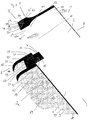
- FIG. 1 shows the area around the first end 3 of a preferred embodiment of a coupling closure according to the invention 1.
- the coupling closure 1 is composed of a first closure strip 5, a second closure strip 7 and the coupling closure 9.
- the first and second closure strips can be integral with the front and rear side wall be connected to a flexible bag.
- the cross section of the first and second closure elements according to the invention (in YZ plane) is initially constant starting from the plant side. Accordingly, both the end stops and a portion of the holding portions (apart from the recess 61) have a substantially constant cross section (in the Y direction). Beginning at the edges 41 and 43, the first and second sealing strips taper, respectively, until they have reached a relatively thin-walled cross-section.
- the minimum cross-section obtained is maintained for a certain length.
- the taper affects the contour of the outer wall of the closure strip, but not the contour of the inner wall.
- the inner wall of the closure strips can, as shown, preferably lay in a flat plane.
- the tapered portions of the closure strips are preferred weld surfaces for flexible bag edges of environmentally sealed containers.
- the first closure strip 5 and the second closure strip 7 are provided with end stops 15 and 17 at their respective first ends 3.
- the first closure strip 5 has a first closure element 19 in the form of a longitudinal groove
- the second closure strip 7 has a second closure element 21 in the form of a longitudinal spring.
- the groove 19 as well as the spring 21 are respectively mounted on the abutment side 23 and 25 of the first and second closure strip 5 and 7 respectively.
- the first and second closure strips 5 and 7 have retaining sections 27 and 29 at least at the first end 3.
- the closure strips 5 and 7 have a longitudinal alignment between the first end 3 and the second end 31 (not shown), i. the abutment sides 23 and 25 extend between the first and second ends in the longitudinal direction (X-direction).
- each closure strip has a thickness or width (distance between the respective outer sides 33, 35 and inner sides 37, 39 of the first and second closure strip (Y-direction).)
- each closure strip or the base body of the closure strip also has transverse to the longitudinal direction over a height extent (Z-direction), which is characterized on one side by the plant sides 23 and 25 and on the other side by the edges 75 and 77.
- Retaining portions 27 and 29 extend beyond the end stops 15 and 17 of the first and second closure strips 5, 7, respectively. These holding portions constitute extensions of the closure strips 5, 7 in longitudinal alignment.
- the respective holding portions 27 and 29 set in the Z direction where the stops 15 and 17 stop.
- the end stops 15 and 17 at a right angle in the holding sections 27 and 29 over.
- the outer and inner sides 33a, 35a and 37a, 39a of the holding portions 27, 29 generally form seamlessly a uniform surface with the inner and outer sides 33, 37; 35, 39 of the closure strips beyond the end stops.
- these outer and inner sides of the holding portions by a contact surface 45, 47, which extends parallel to the contact side 23, 25 of the first and second closure strip 5, 7, respectively.
- the inner sides 37a, 39a of the holding portions 27, 29 of the first and second closure strip 5, 7 are also close to each other can be applied, and preferably firmly connected. Inserting the inner sides 37, 39 of the first and second closure strip 5, 7 close to each other, so that the respective first and second ends 3, 31 and thus the respective end stops 15, 17 are adjacent to each other, the surfaces of the respective end stops lie in a common curved or plan, especially plan level, as in Fig. 1 shown.
- the two end stops 15, 17 of first and second closure strip 5, 7 uniformly dimensioned at least in the Z direction, so that the contact surfaces 45, 47 of the holding portions 27, 29 of the first and second closure strip and the plant sides 23, 25 of the first and second closure strip 5, 7 a curved or planar plane, in particular to form a plane plane.
- the closure 1 has a coupling closure 9.
- This coupling closure 9 has a longitudinal extension in the form of a strip 49 between the first and second end like the closure strips.
- This strip 49 is provided with a support side 51 adjacent to it in a longitudinal orientation to each other third and fourth closure elements 53, 55 are present.
- the third shutter member 53 is a spring and the fourth shutter member 55 is a groove.
- the third shutter member 53 is complementary to the first shutter member 19 in the form of a groove of the first shutter bar 5.
- the fourth shutter member 55 is complementary to the second shutter member 21 in the form of a spring of the second closure strip 7.
- the coupling closure 9 At the first end 3a of the coupling closure 9 there is an end stop 57 which extends at the first end between the support side 51 and the side 59 opposite the support side.
- the first and third 19, 53 and second and fourth closure elements 21, 55 have been coordinated in such a way that the tineumble 23, 25 of the first and second sealing strip in each case rest sealingly on the support side 51 of the coupling closure 9.
- the distance between the third and fourth closure element 53, 55 of the coupling closure 9 and the thickness of the first and second closure element 19, 21 have been selected such that in the closed, ie coupled state, the respective inner sides 37, 39 of first and second closure strip 5, 7 sealingly abut each other.
- the holding sections 27, 29 are also each equipped with a guide element 61, the operation of which will be described in more detail below.
- the thickness or height of the end stop 57 of the coupling closure 9 is substantially equal to the height of the end stops 15, 17 (also in Z-orientation) of the first and second closure strip.
- the thickness of the closure strips 5, 7 (in the Y direction) in the region of the end stops preferably greater than the thickness in the region of the welding surfaces 11, 13 for the subsequent bag walls.
- the transition from closure strip to bag wall can be made jumpy continuously.
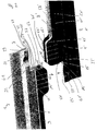
- FIG. 2 shows two coupling closures 1, 1 'according to the invention shortly before the docking operation.
- the docking operation has in an initial stage to the goal, the end stops 15, 17 of the first and second closure strip 5, 7 of the first coupling closure 1 with the end stop 57 'of the coupling closure 9' of the second coupling closure 1 'and the end stops 15', 17 'of first and second closure strip 5 ', 7' of the second closure 1 'with the end stop 57 of the coupling closure 9 of the first coupling closure 1 in such a way to bear that the complementary first closure elements 19, 19' of the first and second coupling closure 1, the first 'and the complementary second closure elements 21, 21' of the first and second coupling closure 1, 1 'by mutual displacement of the two coupling closures 1, 1' according to the invention or the coupling closures 9; 9 'and / or closure strips 15, 17; 15 ', 17' can be coupled together in longitudinal alignment.
- first and second coupling closure 1, 1 ' requires that the complementary first closure elements 19, 19' and the complementary second closure elements 21, 21 'of the first and second coupling closure engage each other unhindered, whereby the respective coupling closures 9, 9' be successively forced out of their connection with these closure elements.
- the dimensions of the end stops 15 ', 17' of the first and second closure strip 5 ', 7' of the second coupling closure 1 'on the end stop 57 of the coupling closure 9 of the first coupling closure 1 are tuned.
- the inner sides of the indentation 67, 67 'forming side walls 63, 65; 63 ', 65' of the coupling closures 9, 9 'of the first and second coupling closure 1, 1' are equipped with guide elements 71, 71 'which are in complementary guide elements 61 and 61' on the outer sides 33, 33 'of the respective holding portions 25, 27 and 25 ', 27' engage in docking.
- the position of these complementary guide elements 61, 71 'and 61', 71 is selected such that the complementary first and second closure elements to be coupled to the first and second closure strips of the first and second coupling closure are unproblematically feasible.
- the indentations 67, 67 'of the coupling closure 9 forming side walls 63, 65 also have the purpose to serve as a preferred grip or breakpoints in particular manual docking.
- the first coupling closure 1 and the coupling closure 9 'of the second coupling closure 1' a particularly reliable docking be accomplished. Because in this way the respectively abutting closure strips of the coupling closures according to the invention are taken safely and reliably during docking.
- FIG. 3 shows a docking device 101 according to the invention, in which the two coupling closures 1, 1 'according to the invention are coupled in the region of their respective adjacent first ends 3, 3'.
- This arrangement is obtained in that the coupling closures 1, 1 ', as in FIG. 2 indicated by the arrow symbols to be moved towards each other to the mutual attachment.
- the coupling closures 9, 9 'of the first and second coupling closure 1, 1' are made of flexible plastics in the illustrated embodiment, as well as the closure strips 5, 5 ', 7, 7' of the first and second coupling closure 1, 1 '.
- the use of complementary guiding elements on the insides of the side walls of the indentation has proven to be particularly useful.
- Particularly preferred is such an embodiment, in which the indentations 67 of the coupling closure 9 forming side walls 63, 65 have on their opposite inner sides further clamping or holding elements.
- These clamping or holding elements can, for example, as in FIG. 1 . 2 . 3 . 4 shown, in the direction of the respective opposite side wall facing projections 73, which are arranged as far away from the support side 51 opposite side 59, be.
- FIG. 4 shows a docking device 101 according to the invention in the coupled state.
- first closure strips 5, 5 'of the first and second coupling closure 1, 1' via their complementary first closure elements 19, 19 'and the second closure strips 7, 7' of the first and second coupling closure 1, 1 'via their complementary second closure elements 21, 21 'sealingly connected to each other over their entire length in longitudinal extent.
- the respective coupling closures 9, 9 'of the first and second coupling closure 1, 1' via the holding portions 27, 29 and 27 ', 29' connected to the respective closure strips.
- the closure elements 53, 55; 53 ', 55' of the coupling closures 9, 9 'in this embodiment are no longer in engagement with the closure elements of the first and the second coupling closure 1, 1' before.
- the inner sides 35, 39; 35 ', 39' of the first and second closure strips 5, 7; 5 ', 7' of the coupling closures 1, 1 ' according to the invention in the region of the end stops and in particular also in the region of the inner sides of the holding sections 27, 29; 27 ', 29' permanently sealed, for example glued or integrally connected.
- the method according to the invention for emptying or loading and / or transferring bulk material with the aid of the inventive coupling fasteners 1, 1 'or the docking device 101 according to the invention will be described below on the basis of the drawings discussed above.
- the first coupling closure 1 according to the invention as in FIG. 3 reproduced, the opening of an inliner closes, as it is used for example in so-called big bags for products used in the food industry products.
- the second coupling closure 1 'according to the invention should in the present case represent the opening of a flexible filling hose which is connected to a storage container.
- the coupling closures 1, 1 'present in the closed state are in the range their end stops 15, 17 to be coupled; 15 ', 17', as in the Figures 2 and 3 reproduced, led together.
- the end stops are at this stage of the process in such a way that the first closure element 19 of the first closure strip 5 of the first coupling closure 1 in the complementary first closure element 19 'of the first closure strip 5' of the second coupling closure 1 'and the second closure element 21 of the second closure strip of the first coupling closure 1 engage in the complementary second closure element 21 'of the second closure strip 7' of the second coupling closure 1 '.
- the docking of the two coupling closures 1, 1 'according to the invention can now be accomplished by holding the side walls 63, 65 of the indentation 67 of the coupling closure 9 of the first coupling closure 1 in order to secure the closure strips 5', 7 'of the second coupling closure 1' left in the Figure 4 ) over the closure strips 5, 7 of the first coupling closure 1 to pull.
- the plant sides slide 23, 23 ', 25, 25' of the first and second coupling closure 1, 1 'one above the other.
- the side walls 63 ', 65' of the coupling closure 9 'of the second coupling closure 1' can be kept to the first and second closure strips 5, 7 of the first coupling closure 1 (to the right in FIG. 3 ), as described above, with the closure strips 5 ', 7' of the second coupling closure 1 'to connect. Furthermore, it is possible by holding the side walls 63, 65; 63 ', 65' of the coupling closures 9, 9 'of the first and second coupling closure 1, 1', the closure strips of these closures relative to each other to move toward each other. In each of the preceding variants, a coupled docking device 101, as in FIG FIG. 4 shown, received.
- This docking device can now be separated again, namely environmentally sealed, in that the third and fourth closure elements 53, 55 of the first coupling closure 1 are reintroduced into the complementary first and second closure elements 19, 21 of the first coupling closure 1.
- the first and second closure elements 19 ', 21' of the second coupling closure 1 ' are automatically reinserted into the complementary third and fourth closure elements 53', 55 'of the second closure. Accordingly, the coupling closures 1, 1 'to be coupled are automatically opened during the docking operation, while they are automatically closed again during decoupling.
- bulk material can thus be removed from a storage container, e.g. a silo to be filled into the inliner of a big bag. If the filling process is completed and no further bulk material material is transferred, as described above, the docking device can be decoupled again. During the entire process, it is ensured that the bulk material to be filled into the inliner neither escapes to the outside nor can components from outside contaminate the bulk material.
- a storage container e.g. a silo to be filled into the inliner of a big bag.
Landscapes
- Engineering & Computer Science (AREA)
- Mechanical Engineering (AREA)
- Bag Frames (AREA)
- Basic Packing Technique (AREA)
Claims (27)
- Fermeture de couplage (1) pour un emballage flexible au moins par secteur, comprenant
une première glissière de fermeture (5) avec une première extrémité (3) et une seconde extrémité (31) opposée en extension longitudinale (direction X), une face intérieure (37), une face extérieure (33) et une face de contact (23), qui relie la face intérieure et la face extérieure l'une avec l'autre, la face de contact (23) présentant en extension longitudinale au moins par secteur au moins un premier élément de fermeture (19) ;
une deuxième glissière de fermeture (7) avec une première extrémité (3) et une seconde extrémité (31) opposée en extension longitudinale, une face intérieure (39), une face extérieure (35) et une face de contact (25), qui relie la face intérieure et la face extérieure l'une avec l'autre, la face de contact (25) présentant en extension longitudinale au moins par secteur au moins un deuxième élément de fermeture (21), les première et seconde extrémités (3, 31) des première et deuxième glissières de fermeture (5, 7) étant en outre respectivement adjacentes, dans le cas d'un contact mutuel des faces intérieures (37, 39) de ces glissières de fermeture, et les premier et deuxième éléments de fermeture (19, 21) s'étendant jusqu'aux premières extrémités voisines et/ou jusqu'aux deuxièmes extrémités voisines (3, 31) ; et
une fermeture d'accouplement (9), comprenant une glissière (49) avec une première et une deuxième extrémité (3a, 31a) en extension longitudinale, la première et/ou la deuxième extrémité présentant une butée de fin de course (57), et une face d'appui (51), comprenant en extension longitudinale sur la face d'appui (51) au moins par secteur un troisième élément de fermeture (53), qui est couplé ou peut être couplé de manière réversible, en particulier étanche à l'environnement, avec le premier élément de fermeture (19), et est espacé, en particulier espacé de manière équidistante, par rapport, au moins par secteur, à un quatrième élément de fermeture (55), qui est couplé ou peut être couplé de manière réversible, en particulier étanche à l'environnement, avec le deuxième élément de fermeture (21). - Fermeture de couplage (1) selon la revendication 1, caractérisée en ce que
la première et/ou la deuxième extrémité de la fermeture d'accouplement (9) présente(nt) une butée de fin de course (57), la première et/ou la deuxième extrémité (3, 31) de la première glissière de fermeture (5) présente(nt) une butée de fin de course (15) et la première extrémité et/ou la deuxième extrémité (3, 31) de la deuxième glissière de fermeture présente(nt) une butée de fin de course (17), chaque extrémité voisine respective d'une fermeture d'accouplement ainsi que des première et deuxième glissières de fermeture présentant une butée de fin de course (15, 17), et les premier et deuxième éléments de fermeture (19, 21) s'étendent jusqu'aux butées de fin de course voisines (15, 17) des première et deuxième glissières de fermeture (5, 7), et les troisième et quatrième éléments de fermeture (53, 55) s'étendent jusqu'à la butée de fin de course de la fermeture d'accouplement (9), qui est adjacente aux butées de fin de course voisines les unes des autres des première et deuxième glissières de fermeture. - Fermeture de couplage (1) selon la revendication 1 ou 2, caractérisée en ce que
la première et/ou la deuxième glissières de fermeture (5, 7) présente(nt) selon une orientation longitudinale au niveau de la première et/ou de la deuxième extrémité (3, 31) un secteur de retenue (27, 29), contenant des première ou deuxième surfaces d'appui (45, 47) ainsi qu'une face intérieure et une face extérieur (37a, 39a ; 33a, 35a). - Fermeture de couplage (1) selon l'une quelconque des revendications précédentes, caractérisée en ce que
les première et/ou deuxième glissières de fermeture (5, 7) sont prolongées selon une orientation longitudinale au niveau des première et/ou deuxième extrémités (3, 31) par les première ou deuxième butées de fin de course (4, 17) et selon une orientation transversale (direction Z) éloignée des faces de contact (23, 25) et de manière consécutive au niveau des première et/ou deuxième butées de fin de course (15, 17) sous la forme de secteurs de retenue (27, 29), contenant une première ou deuxième surface surfaces de contact (45, 47), ainsi qu'une face intérieure et une face extérieure (37a, 39a ; 33a, 35a), s'étendant depuis les première et/ou deuxième butées de fin de course (15, 17), en particulier de sorte que les première et/ou deuxième butées de fin de course (15, 17) puissent être mises en contact avec la butée de fin de course d'une fermeture d'accouplement d'une deuxième fermeture de couplage. - Fermeture de couplage (1) selon l'une quelconque des revendications 3 à 4, caractérisée en ce que
la fermeture d'accouplement (9) présente selon une orientation transversale (direction Z), entre la face d'appui (51) et la face (59) opposée à la face d'appui dans le secteur de la butée de fin de course (57), une épaisseur qui correspond essentiellement à l'espace entre la surface de contact (45, 47) du secteur de retenue (27, 29) des première et/ou deuxième glissières de fermeture (5, 7), à l'endroit où les surfaces de contact (45, 47) rencontrent les première ou deuxième butées de fin de course (15, 17), et la face de contact (23, 25) des première ou deuxième glissières de fermeture (5, 7). - Fermeture de couplage selon l'une quelconque des revendications précédentes, caractérisée en ce que
les première et deuxième glissières de fermeture sont fabriquées essentiellement en une matière plastique flexible et la fermeture d'accouplement est également fabriquée en une matière plastique flexible ou en un matériau plus rigide, en particulier en matière plastique ou en métal. - Fermeture de couplage (1) selon l'une quelconque des revendications précédentes, caractérisée en ce que
les éléments de fermeture (19, 21) des première et deuxième glissières de fermeture (5, 7) présentent respectivement une rainure, et les troisième et quatrième éléments de fermeture (53, 55) de la fermeture d'accouplement (9) présentent respectivement une languette, qui est complémentaire à la rainure de la première ou deuxième glissière de fermeture (5, 7), de sorte que la languette et la rainure peuvent être mises en prise respectivement de manière réversible, en particulier étanche à l'environnement ;
ou les premier et deuxième éléments de fermeture (19, 21) des première et deuxième glissières de fermeture (5, 7) présentent respectivement une languette, et les troisième et quatrième éléments de fermeture (53, 55) de la fermeture d'accouplement (9) présentent une rainure, qui sont complémentaires de la languette de la première ou deuxième glissière de fermeture (5, 7), de sorte que la rainure et la languette peuvent être mises en prise de manière respectivement réversible, en particulier étanche à l'environnement ; ou de sorte que le premier élément de fermeture (19) de la première glissière de fermeture (5) présente une rainure et le deuxième élément de fermeture (21) de la deuxième glissière de fermeture (7) présente une languette, ainsi que de sorte que le troisième élément de fermeture (53) de la fermeture d'accouplement (9) présente une languette, qui est complémentaire de la rainure de la première glissière de fermeture (5), et le quatrième élément de fermeture (5) de la fermeture d'accouplement (9) présente une rainure qui est complémentaire de la languette de la deuxième glissière de fermeture (7), de sorte que la rainure et la languette peuvent être mises en prise de manière respectivement réversible, en particulier étanche à l'environnement ; - Fermeture de couplage (1) selon l'une quelconque des revendications précédentes, caractérisée en ce que
la glissière de la fermeture d'accouplement (9) dans le secteur des première et/ou deuxième extrémités (3a, 31 a), en particulier dans le secteur de la butée de fin de course (57) des première et/ou deuxième extrémités (3a, 31 a), présente selon une orientation longitudinale un dispositif de réception, en particulier une bosse rentrante (67), pour la réception du secteur de retenue d'une première et/ou deuxième glissière de fermeture d'une deuxième fermeture de couplage, en particulier sous la forme de parois latérales espacées (63, 65), qui s'étendent depuis la face (59) opposée à la face d'appui (51) de la glissière (49) en particulier au moins par secteur jusque dans des parois essentiellement parallèles. - Fermeture de couplage selon la revendication 8, caractérisé en ce que
le dispositif de réception (67) est relié ou peut être relié avec la glissière (49) d'un seul tenant ou de manière séparée, en particulier par une connexion par fiche ou une connexion par clip. - Fermeture de couplage (1) selon la revendication 9, caractérisé en ce que
le dispositif de réception (67), en particulier au moins une face inférieure des parois latérales espacées (63, 65) de ce dispositif de réception (67), présente au moins un élément de guidage (71), qui peut être mis en prise avec un élément de guidage complémentaire (61) du secteur de retenue des première et/ou deuxième glissières de fermeture d'une deuxième fermeture de couplage. - Fermeture de couplage (1) selon l'une quelconque des revendications 3 à 10, caractérisée en ce que
au moins un secteur de retenue (27, 29) des première et/ou deuxième glissières de fermeture présente sur sa face extérieure (33a, 35a) au moins un élément de guidage (61) qui peut être mis en prise avec un élément de guidage complémentaire de la fermeture d'accouplement d'une deuxième fermeture de couplage. - Fermeture de couplage (1) selon l'une quelconque des revendications précédentes, caractérisée en ce que
les premier et troisième éléments de fermeture (19, 53) et/ou les deuxième et quatrième éléments de fermeture (21, 55) sont ajustés les uns sur les autres de sorte que la face de contact (23, 25) des première ou deuxième glissières de fermeture (5, 7) et la face d'appui (51) de la fermeture d'accouplement (9), à l'état couplé, au moins par secteur sont juxtaposées les unes au niveau des autres de manière étanche ou peuvent être juxtaposées les unes au niveau des autres de manière étanche ; et/ou
les troisième et quatrième éléments de fermeture (53, 55) présentent une distance de l'un à l'autre, de sorte que les faces intérieures (37, 39) des première et deuxième glissières de fermeture (5, 7), à l'état couplé avec le premier ou deuxième élément de fermeture (19, 21), sont juxtaposées, ou peuvent être juxtaposées l'une au niveau de l'autre au moins par secteur, en particulier de manière étanche. - Fermeture de couplage (1) selon l'une quelconque des revendications précédentes, caractérisée en ce que
le premier et le deuxième élément de fermeture (19, 21) sont essentiellement de la même longueur selon une orientation longitudinale,
et/ou le troisième et le quatrième élément de fermeture (53, 55) sont essentiellement de la même longueur en extension longitudinale et vont en particulier de manière parallèle, et/ou le premier et le troisième élément de fermeture (19, 53) et/ou le deuxième et le quatrième élément de fermeture (21, 55) sont essentiellement de la même longueur selon une orientation longitudinale. - Fermeture de couplage (1) selon l'une quelconque des revendications précédentes, caractérisée en ce que
la première et la deuxième glissière de fermeture (5, 7) sont reliées l'une avec l'autre par l'intermédiaire de leurs extrémités (3, 31) respectivement voisines, en particulier par l'intermédiaire de secteurs de retenue (27, 29) voisins et/ou par l'intermédiaire des secteurs de face intérieure voisins des butées de fin de course de butées de fin de course voisine, en particulier avec formation d'un périmètre fermé. - Fermeture de couplage (1) selon l'une quelconque des revendications précédentes, caractérisée par
un emballage flexible au moins par secteur, en particulier sous la forme d'une poche ou d'un moyen d'approvisionnement, dont le bord d'ouverture est relié de manière séparée ou d'un seul tenant avec la première et la deuxième glissière de fermeture. - Fermeture de couplage (1) selon l'une quelconque des revendications précédentes, caractérisée par
au moins une première aide au réglage présente au niveau des première et/ou deuxième extrémités (3a, 31a), en particulier dans et/ou sur la butée de fin de course, de la fermeture d'accouplement, en particulier sous la forme d'au moins une cheville ou un accès, pour la réception d'une deuxième aide au réglage d'une deuxième fermeture de couplage à coupler, en particulier pour recevoir une aide au réglage complémentaire dans et/ou sur la butée de fin de course des première et/ou deuxième glissières d'une deuxième fermeture de couplage pouvant être connectée ;
et/ou caractérisée par
au moins une deuxième aide au réglage présente au niveau des première et/ou deuxième extrémités (3a, 31a), en particulier dans et/ou sur la butée de fin de course, des première et/ou deuxième glissières de fermeture, en particulier sous la forme d'au moins une cheville ou un accès, pour recevoir une aide au réglage complémentaire d'une deuxième fermeture de couplage à coupler, en particulier pour recevoir une aide au réglage complémentaire dans et/ou sur la butée de fin de course d'une fermeture d'accouplement d'une deuxième fermeture de couplage pouvant être connectée. - Fermeture de couplage (1) selon l'une quelconque des revendications précédentes, caractérisée en ce que
une première aide au centrage, en particulier selon une orientation longitudinale, est présente sur la surface d'appui (45, 47) d'au moins un premier et/ou deuxième secteur de retenue (27, 29), qui peut être mise en prise avec une deuxième aide au centrage complémentaire sur la face opposée à la face d'appui de la fermeture d'accouplement d'une fermeture de couplage pouvant être connectée ;
et/ou au moins une deuxième aide au centrage, en particulier selon une orientation longitudinale, est présente sur la face (59) opposée à la face d'appui de la fermeture d'accouplement (9), qui peut être mise en prise avec une première aide au centrage complémentaire sur la surface d'appui d'un premier et/ou d'un deuxième secteur de retenue d'une fermeture de couplage pouvant être connectée. - Fermeture de couplage (1) selon l'une quelconque des revendications précédentes, caractérisée en ce que
les première et/ou deuxième glissières de fermeture (5, 7), en particulier espacées de la face de contact (dans la direction Z), présentent une surface d'attache, en particulier une surface de soudure, pour le bord d'ouverture des emballages, en particulier avec une épaisseur (dans la direction Y) qui est inférieure au moins par secteur à l'épaisseur des première ou deuxième glissières de fermeture dans le secteur des butées de fin de course. - Dispositif de connexion (101) pour le vidage, le remplissage et/ou le transvasement de produit en vrac, en particulier étanche à l'environnement, comprenant une première et une deuxième fermeture de couplage (1, 1') selon l'une quelconque des revendications précédentes, la première et la deuxième glissière de fermeture (5, 7) de la première fermeture de couplage (1) et la première et la deuxième glissière de fermeture (5', 7') de la deuxième fermeture de couplage (1') étant essentiellement de la même longueur, et les premier et deuxième éléments de fermeture (19, 21) des première et deuxième glissières de fermeture (5, 7) de la première fermeture de couplage (1) étant complémentaires aux premier et deuxième éléments de fermeture (19', 21') des première et deuxième glissières de fermeture (5', 7') de la deuxième fermeture de couplage (1'), de sorte que les première et deuxième glissières de fermeture (5, 5', 7, 7') des première et deuxième fermetures de couplage (1, 1') sont reliées ou peuvent être reliées les unes avec les autres de manière réversible, en particulier étanche à l'environnement.
- Dispositif de connexion (101) selon la revendication 19, caractérisé en ce que
la première et/ la deuxième fermeture de couplage (1, 1') peuvent être reliées ou sont reliées par un emballage flexible, en particulier sous la forme d'un conteneur ou d'un moyen d'approvisionnement, de manière séparée ou d'un seul tenant. - Dispositif de connexion (101) selon la revendication 19 ou 20, caractérisé en ce que
la première et la deuxième fermeture de couplage (1, 1') sont essentiellement identiques. - Dispositif de connexion (101) selon l'une quelconque des revendications 19 à 21, caractérisé en ce que
les troisième et quatrième éléments de fermeture de la fermeture d'accouplement de la première fermeture de couplage demeure dans l'état connecté des première et deuxième fermetures de couplage, en prise par secteur avec les premier et deuxième éléments de fermeture des première et deuxième glissières de fermeture de la première fermeture de couplage, et/ou les troisième et quatrième éléments de fermeture de la fermeture d'accouplement de la deuxième fermeture de couplage demeurent, dans l'état connecté, en prise par secteur avec les premier ou deuxième éléments de fermeture des première et deuxième glissières de fermeture de la deuxième fermeture de couplage. - Emballage flexible au moins par secteur, contenant au moins une fermeture de couplage selon l'une quelconque des revendications 1 à 18.
- Procédé pour le remplissage, le transvasement et/ou le vidage, en particulier étanche à l'environnement, d'emballages, comprenant les étapes consistant à :- mettre à disposition un premier emballage flexible au moins dans un secteur d'ouverture, en particulier selon la revendication 23, contenant au moins une première fermeture de couplage, présente de manière au moins partiellement fermée, selon l'une quelconque des revendications 1 à 18,- mettre à disposition un deuxième emballage flexible au moins dans un secteur d'ouverture, en particulier selon la revendication 23, contenant au moins une deuxième fermeture de couplage, présente de manière au moins partiellement fermée, selon l'une quelconque des revendications 1 à 18,- mettre en contact la première extrémité du premier élément de fermeture de la première glissière de fermeture de la première fermeture de couplage au niveau de la première extrémité d'un premier élément de fermeture complémentaire d'une première glissière de fermeture de la deuxième fermeture de couplage et mettre en contact la première extrémité du deuxième élément de fermeture de la deuxième glissière de fermeture de la première fermeture de couplage au niveau de la première extrémité du deuxième élément de fermeture complémentaire de la deuxième glissière de fermeture de la deuxième fermeture de couplage, de sorte que les premier et deuxième éléments de fermeture complémentaires respectifs des première et deuxième fermetures de couplage peuvent être mis en prise par un déplacement axial,- mettre en prise mutuelle les premier et deuxième éléments de fermeture respectifs complémentaires par un déplacement axial, les troisième et quatrième éléments de fermeture des fermetures d'accouplement des première et deuxième fermetures de couplage étant libérés successivement de la connexion avec les premier et deuxième éléments de fermeture des première et deuxième fermetures de couplage, de préférence jusqu'à ce que la première extrémité de la fermeture d'accouplement de la première fermeture de couplage soit présente dans le secteur de la deuxième extrémité de la première fermeture de couplage et jusqu'à ce que la première extrémité de la fermeture d'accouplement de la deuxième fermeture de couplage soit présente dans le secteur de la deuxième extrémité de la première fermeture de couplage,- transférer du produit en vrac à partir du premier emballage jusque dans le deuxième emballage, ou inversement,- déplacer la première extrémité de la fermeture d'accouplement de la première fermeture de couplage en direction de la première extrémité de cette fermeture de couplage et déplacer la première extrémité de la fermeture d'accouplement de la deuxième fermeture de couplage en direction de la première extrémité de cette fermeture de couplage, de sorte que les troisième et quatrième éléments de fermeture de la fermeture d'accouplement de la première fermeture de couplage sont mis en prise successivement avec les premier et deuxième éléments de fermeture complémentaires des première et deuxième glissières de fermeture de la première fermeture de couplage, et de sorte que les troisième et quatrième éléments de fermeture de la fermeture d'accouplement de la deuxième fermeture de couplage sont mis en prise successivement avec les premier et deuxième éléments de fermeture complémentaire des première ou deuxième glissières de fermeture de la deuxième fermeture de couplage, en particulier jusqu'à ce que les premier et deuxième éléments de fermeture de la première fermeture de couplage ne soient plus en prise avec les premier et deuxième éléments de fermeture complémentaires de la deuxième fermeture de couplage, de sorte que les premier et deuxième emballages sont séparés l'une de l'autre.
- Procédé selon la revendication 24, caractérisé en ce que
la butée de fin de course de la fermeture d'accouplement de la première fermeture de couplage est amenée, en particulier mise en contact au niveau des butées de fin de course des première et deuxième glissières de fermeture de la deuxième fermeture de couplage, et la butée de fin de course de la fermeture d'accouplement de la deuxième fermeture de couplage est amenée, en particulier mise en contact au niveau des butées de fin de course des première et deuxième glissières de fermeture de la première fermeture de couplage, de sorte que la face d'appui de la fermeture d'accouplement de la première fermeture de couplage passe, au moins dans le secteur des butées de fin de course, de manière essentiellement parallèle aux faces de contact des première et deuxième glissières de fermeture de la deuxième fermeture de couplage et/ou de sorte que la face d'appui de la fermeture d'accouplement de la deuxième fermeture de couplage passe de manière essentiellement parallèle aux faces de contact des première et deuxième glissières de fermeture de la première fermeture de couplage. - Procédé selon la revendication 24 ou 25, caractérisé en ce que
les première et deuxième surfaces de contact des premier et deuxième secteurs de retenue de la première fermeture de couplage sont mises en contact selon une orientation axiale sur les faces opposées aux faces d'appui de la glissière de la fermeture d'accouplement de la deuxième fermeture de couplage, et/ou les première et deuxième surfaces de contact des premier et deuxième secteurs de retenue de la deuxième fermeture de couplage sont mises en contact au niveau des faces opposées aux faces d'appui de la glissière de la fermeture d'accouplement de la première fermeture de couplage. - Procédé selon la revendication 26, caractérisé en ce que
les premier et deuxième secteurs de retenue de la première fermeture de couplage sont introduits dans une bosse rentrante de la fermeture d'accouplement de la deuxième fermeture de couplage et/ou les premier et deuxième secteurs de retenue de la deuxième fermeture de couplage sont introduits dans une bosse rentrante de la fermeture d'accouplement de la première fermeture de couplage.
Priority Applications (6)
| Application Number | Priority Date | Filing Date | Title |
|---|---|---|---|
| AT06014378T ATE426552T1 (de) | 2006-07-11 | 2006-07-11 | Kupplungsverschluss fur ein flexibles gebinde, eine andockeinrichtung fur flexible gebinde, ein verfahren zum entleeren, be- und/oder umfullen von schuttgut aus flexiblen gebinden und zwei umweltdicht gekoppelte flexible gebinde |
| DE502006003268T DE502006003268D1 (de) | 2006-07-11 | 2006-07-11 | Kupplungsverschluss für ein flexibles Gebinde, eine Andockeinrichtung für flexible Gebinde, ein Verfahren zum Entleeren, Be- und/oder Umfüllen von Schüttgut aus flexiblen Gebinden und zwei umweltdicht gekoppelte flexible Gebinde |
| EP06014378A EP1880942B1 (fr) | 2006-07-11 | 2006-07-11 | Arrangement de fermeture et d'accrochage pour un sac flexible, procédé pour vider et/ou remplir le matériel en vrac à partir des sacs flexibles et de deux sacs flexibles couplés |
| PCT/EP2007/006132 WO2008006557A1 (fr) | 2006-07-11 | 2007-07-11 | Verrou de couplage pour une gerbe flexible, module d'accrochage pour gerbes flexibles, procédé de vidage, de remplissage et/ou transvasement de matériau en vrac depuis des gerbes flexibles et deux gerbes flexibles couplées isolées de l'environnement |
| JP2009518783A JP2009542542A (ja) | 2006-07-11 | 2007-07-11 | 可撓性容器のための連結ファスナー、可撓性容器のためのドッキング装置、可撓性容器からのバルク材を出すか、充填するか、もしくは再充填する方法、および、周囲に対してしっかりと連結された2つの可撓性容器 |
| US12/373,290 US20100294396A1 (en) | 2006-07-11 | 2007-07-11 | Coupling fastener for a flexible container, a docking device for flexible containers, a method for emptying, filling or refilling bulk material from flexible containers, and two flexible containers which are coupled tightly with respect to the environment |
Applications Claiming Priority (1)
| Application Number | Priority Date | Filing Date | Title |
|---|---|---|---|
| EP06014378A EP1880942B1 (fr) | 2006-07-11 | 2006-07-11 | Arrangement de fermeture et d'accrochage pour un sac flexible, procédé pour vider et/ou remplir le matériel en vrac à partir des sacs flexibles et de deux sacs flexibles couplés |
Publications (2)
| Publication Number | Publication Date |
|---|---|
| EP1880942A1 EP1880942A1 (fr) | 2008-01-23 |
| EP1880942B1 true EP1880942B1 (fr) | 2009-03-25 |
Family
ID=37685031
Family Applications (1)
| Application Number | Title | Priority Date | Filing Date |
|---|---|---|---|
| EP06014378A Not-in-force EP1880942B1 (fr) | 2006-07-11 | 2006-07-11 | Arrangement de fermeture et d'accrochage pour un sac flexible, procédé pour vider et/ou remplir le matériel en vrac à partir des sacs flexibles et de deux sacs flexibles couplés |
Country Status (6)
| Country | Link |
|---|---|
| US (1) | US20100294396A1 (fr) |
| EP (1) | EP1880942B1 (fr) |
| JP (1) | JP2009542542A (fr) |
| AT (1) | ATE426552T1 (fr) |
| DE (1) | DE502006003268D1 (fr) |
| WO (1) | WO2008006557A1 (fr) |
Families Citing this family (1)
| Publication number | Priority date | Publication date | Assignee | Title |
|---|---|---|---|---|
| DE102019123335B4 (de) | 2019-08-30 | 2021-10-07 | Andocksysteme G. Untch Gmbh | Andockverschluss und Verfahren zum kontaminationsfreien Verbinden einer ersten flexiblen Umhüllung mit einer zweiten flexiblen Umhüllung, flexible Umhüllung mit einem derartigen Andockverschluss sowie Vorrichtung und Verfahren zum Befüllen von flexiblen Umhüllungen |
Family Cites Families (15)
| Publication number | Priority date | Publication date | Assignee | Title |
|---|---|---|---|---|
| US2064432A (en) * | 1936-04-25 | 1936-12-15 | Internat Seal And Knot Protect | Sealable container |
| US4541117A (en) * | 1983-07-28 | 1985-09-10 | Martin I. Davis | Sealing closure for a flexible container |
| JPS6216319A (ja) * | 1985-07-11 | 1987-01-24 | 呉羽化学工業株式会社 | 自動充填包装装置 |
| US5655179A (en) * | 1995-06-15 | 1997-08-05 | Mita Industrial Co., Ltd. | Developer replenishing apparatus having engaging mechanisms for preventing toner scatter during toner replenishment |
| JPH10114316A (ja) * | 1996-10-02 | 1998-05-06 | Okabe Lock:Kk | 袋押込み式敷設装置 |
| DE19641827C2 (de) * | 1996-10-10 | 2002-11-21 | Gea Buck Valve Gmbh | Austraghilfe für schwerfließende Schüttgüter aus Behältern |
| US6059456A (en) * | 1997-04-23 | 2000-05-09 | Reynolds Consumer Products, Inc. | Reclosable profile arrangement using slidable closure strip |
| US6074094A (en) * | 1997-06-25 | 2000-06-13 | Manolizi; Jorge Eleuterio | Safety locking for a bag |
| DE20117669U1 (de) * | 2001-10-29 | 2002-03-14 | GEA Buck Valve GmbH, 79379 Müllheim | Abgedichtete Andockeinrichtung insbesondere für Säcke |
| US7097359B2 (en) * | 2003-02-20 | 2006-08-29 | Illinois Tool Works Inc. | Reclosable packaging having slider coupled to top of zipper |
| DE10321814B4 (de) * | 2003-05-15 | 2007-03-01 | Gea Niro Gmbh | Kopplungselement sowie Andockeinrichtung enthaltend ein Kopplungselement |
| DE10362131A1 (de) * | 2003-08-01 | 2006-06-14 | Gea Buck Valve Gmbh | Kupplungsverschlüsse sowie Andockeinrichtungen enthaltend diese Kupplungsverschlüsse |
| FR2867756B1 (fr) * | 2004-03-18 | 2008-05-23 | Morance Soudure | Systeme d'ouverture/fermeture etanche destine a des sacs d'emballages |
| DE202004017855U1 (de) * | 2004-11-17 | 2005-02-17 | Gea Buck Valve Gmbh | Kupplungsverschluß sowie Andockeinrichtung, enthaltend zwei dieser Kupplungsverschlüsse |
| US8043005B2 (en) * | 2006-06-02 | 2011-10-25 | Hydrapak, Inc. | Reservoir closure system and method |
-
2006
- 2006-07-11 AT AT06014378T patent/ATE426552T1/de not_active IP Right Cessation
- 2006-07-11 EP EP06014378A patent/EP1880942B1/fr not_active Not-in-force
- 2006-07-11 DE DE502006003268T patent/DE502006003268D1/de active Active
-
2007
- 2007-07-11 WO PCT/EP2007/006132 patent/WO2008006557A1/fr not_active Ceased
- 2007-07-11 US US12/373,290 patent/US20100294396A1/en not_active Abandoned
- 2007-07-11 JP JP2009518783A patent/JP2009542542A/ja active Pending
Also Published As
| Publication number | Publication date |
|---|---|
| DE502006003268D1 (de) | 2009-05-07 |
| WO2008006557A1 (fr) | 2008-01-17 |
| JP2009542542A (ja) | 2009-12-03 |
| US20100294396A1 (en) | 2010-11-25 |
| EP1880942A1 (fr) | 2008-01-23 |
| ATE426552T1 (de) | 2009-04-15 |
Similar Documents
| Publication | Publication Date | Title |
|---|---|---|
| DE4339436C2 (de) | Seitenfaltenbeutel und Verfahren zu dessen Herstellung | |
| DE69905989T2 (de) | Reissverschluss mit Schieber und Gehäuse, und Beutel mit Reissverschluss | |
| DE69621050T2 (de) | Querangeordnetes Reissverschlussystem | |
| DE69212676T2 (de) | Wiederverschliessbares Kunststoffbefestigungselement mit selbstschliessendem Reissverschluss | |
| EP1441953B1 (fr) | Dispositif d'accrochage etanche destine notamment a des sacs et procede de remplissage et de vidage de contenants isoles de l'environnement | |
| EP1648780B1 (fr) | Fermetures d'accouplement multiples et dispositifs d'adossage multiples renfermant ces fermetures d'accouplement multiples | |
| DE10321814B4 (de) | Kopplungselement sowie Andockeinrichtung enthaltend ein Kopplungselement | |
| EP2455297B1 (fr) | Coulisseau pour relier et séparer deux fermetures chaques dotées de deux baguettes de profilé | |
| DE60200703T2 (de) | Verfahren und Vorrichtung zur Herstellung von wiederverschliessbaren Beuteln | |
| DE4419371C2 (de) | Verbindungsanordnung | |
| WO2005070776A1 (fr) | Fermetures refermables et systemes de connexion contenant de telles fermetures | |
| EP1880942B1 (fr) | Arrangement de fermeture et d'accrochage pour un sac flexible, procédé pour vider et/ou remplir le matériel en vrac à partir des sacs flexibles et de deux sacs flexibles couplés | |
| DE102016115215A1 (de) | Seitenwandanordnung für einen Behälter sowie Verfahren zu dessen Herstellung und Behälter mit einer solchen Seitenwandanordnung | |
| EP1812293A1 (fr) | Fermeture a accouplement, dispositif d'accrochage comportant deux fermetures a accouplement et conteneur presentant au moins une fermeture a accouplement | |
| EP3831734A1 (fr) | Bague de montage ainsi que conteneur de transport pourvu de bague de montage | |
| DE69812719T2 (de) | Stützrahmen für verpackungsbehälter | |
| EP1947039A1 (fr) | Fermeture à accouplement et dispositif d'accrochage comportant deux fermetures à accouplement | |
| DE102018008346B4 (de) | Verschluss | |
| DE102024109407B3 (de) | Wiederverwendbarer Behälter mit einem Verschluss, Verschlussanordnung und deren Verwendung | |
| DE202006007686U1 (de) | Vorrichtung zur Sicherung rollbarer Transportgüter auf einer Transport-Palette | |
| EP1746033B1 (fr) | Récipient, et procédé et dispositif pour sa fabrication | |
| DE19942035A1 (de) | Verfahren und Vorrichtung zum Anbringen von Ausgießern, Verschlussvorrichtungen oder dergleichen Applikationen auf einem Flachbeutel | |
| DE202019100798U1 (de) | Flexibles Sammelbehältnis | |
| EP0635433A1 (fr) | Sac à fermeture à glissière | |
| DE1511004A1 (de) | Aus schlauchfoermigem Material hergestellter Kunststoffsack mit Kreuzbodenfaltung |
Legal Events
| Date | Code | Title | Description |
|---|---|---|---|
| PUAI | Public reference made under article 153(3) epc to a published international application that has entered the european phase |
Free format text: ORIGINAL CODE: 0009012 |
|
| 17P | Request for examination filed |
Effective date: 20070328 |
|
| AK | Designated contracting states |
Kind code of ref document: A1 Designated state(s): AT BE BG CH CY CZ DE DK EE ES FI FR GB GR HU IE IS IT LI LT LU LV MC NL PL PT RO SE SI SK TR |
|
| AX | Request for extension of the european patent |
Extension state: AL BA HR MK YU |
|
| RIN1 | Information on inventor provided before grant (corrected) |
Inventor name: LAIS, PETER Inventor name: KOCH, MARTIN |
|
| GRAP | Despatch of communication of intention to grant a patent |
Free format text: ORIGINAL CODE: EPIDOSNIGR1 |
|
| AKX | Designation fees paid |
Designated state(s): AT BE BG CH CY CZ DE DK EE ES FI FR GB GR HU IE IS IT LI LT LU LV MC NL PL PT RO SE SI SK TR |
|
| GRAS | Grant fee paid |
Free format text: ORIGINAL CODE: EPIDOSNIGR3 |
|
| GRAA | (expected) grant |
Free format text: ORIGINAL CODE: 0009210 |
|
| AK | Designated contracting states |
Kind code of ref document: B1 Designated state(s): AT BE BG CH CY CZ DE DK EE ES FI FR GB GR HU IE IS IT LI LT LU LV MC NL PL PT RO SE SI SK TR |
|
| REG | Reference to a national code |
Ref country code: GB Ref legal event code: FG4D Free format text: NOT ENGLISH |
|
| REG | Reference to a national code |
Ref country code: CH Ref legal event code: EP |
|
| REG | Reference to a national code |
Ref country code: IE Ref legal event code: FG4D Free format text: LANGUAGE OF EP DOCUMENT: GERMAN |
|
| REF | Corresponds to: |
Ref document number: 502006003268 Country of ref document: DE Date of ref document: 20090507 Kind code of ref document: P |
|
| PG25 | Lapsed in a contracting state [announced via postgrant information from national office to epo] |
Ref country code: LT Free format text: LAPSE BECAUSE OF FAILURE TO SUBMIT A TRANSLATION OF THE DESCRIPTION OR TO PAY THE FEE WITHIN THE PRESCRIBED TIME-LIMIT Effective date: 20090325 Ref country code: SI Free format text: LAPSE BECAUSE OF FAILURE TO SUBMIT A TRANSLATION OF THE DESCRIPTION OR TO PAY THE FEE WITHIN THE PRESCRIBED TIME-LIMIT Effective date: 20090325 Ref country code: FI Free format text: LAPSE BECAUSE OF FAILURE TO SUBMIT A TRANSLATION OF THE DESCRIPTION OR TO PAY THE FEE WITHIN THE PRESCRIBED TIME-LIMIT Effective date: 20090325 |
|
| REG | Reference to a national code |
Ref country code: CH Ref legal event code: NV Representative=s name: E. BLUM & CO. AG PATENT- UND MARKENANWAELTE VSP |
|
| PG25 | Lapsed in a contracting state [announced via postgrant information from national office to epo] |
Ref country code: SE Free format text: LAPSE BECAUSE OF FAILURE TO SUBMIT A TRANSLATION OF THE DESCRIPTION OR TO PAY THE FEE WITHIN THE PRESCRIBED TIME-LIMIT Effective date: 20090625 Ref country code: LV Free format text: LAPSE BECAUSE OF FAILURE TO SUBMIT A TRANSLATION OF THE DESCRIPTION OR TO PAY THE FEE WITHIN THE PRESCRIBED TIME-LIMIT Effective date: 20090325 Ref country code: PL Free format text: LAPSE BECAUSE OF FAILURE TO SUBMIT A TRANSLATION OF THE DESCRIPTION OR TO PAY THE FEE WITHIN THE PRESCRIBED TIME-LIMIT Effective date: 20090325 |
|
| REG | Reference to a national code |
Ref country code: IE Ref legal event code: FD4D |
|
| PG25 | Lapsed in a contracting state [announced via postgrant information from national office to epo] |
Ref country code: PT Free format text: LAPSE BECAUSE OF FAILURE TO SUBMIT A TRANSLATION OF THE DESCRIPTION OR TO PAY THE FEE WITHIN THE PRESCRIBED TIME-LIMIT Effective date: 20090831 Ref country code: ES Free format text: LAPSE BECAUSE OF FAILURE TO SUBMIT A TRANSLATION OF THE DESCRIPTION OR TO PAY THE FEE WITHIN THE PRESCRIBED TIME-LIMIT Effective date: 20090706 Ref country code: EE Free format text: LAPSE BECAUSE OF FAILURE TO SUBMIT A TRANSLATION OF THE DESCRIPTION OR TO PAY THE FEE WITHIN THE PRESCRIBED TIME-LIMIT Effective date: 20090325 Ref country code: CZ Free format text: LAPSE BECAUSE OF FAILURE TO SUBMIT A TRANSLATION OF THE DESCRIPTION OR TO PAY THE FEE WITHIN THE PRESCRIBED TIME-LIMIT Effective date: 20090325 |
|
| PG25 | Lapsed in a contracting state [announced via postgrant information from national office to epo] |
Ref country code: RO Free format text: LAPSE BECAUSE OF FAILURE TO SUBMIT A TRANSLATION OF THE DESCRIPTION OR TO PAY THE FEE WITHIN THE PRESCRIBED TIME-LIMIT Effective date: 20090325 Ref country code: SK Free format text: LAPSE BECAUSE OF FAILURE TO SUBMIT A TRANSLATION OF THE DESCRIPTION OR TO PAY THE FEE WITHIN THE PRESCRIBED TIME-LIMIT Effective date: 20090325 Ref country code: IS Free format text: LAPSE BECAUSE OF FAILURE TO SUBMIT A TRANSLATION OF THE DESCRIPTION OR TO PAY THE FEE WITHIN THE PRESCRIBED TIME-LIMIT Effective date: 20090725 |
|
| PG25 | Lapsed in a contracting state [announced via postgrant information from national office to epo] |
Ref country code: IE Free format text: LAPSE BECAUSE OF FAILURE TO SUBMIT A TRANSLATION OF THE DESCRIPTION OR TO PAY THE FEE WITHIN THE PRESCRIBED TIME-LIMIT Effective date: 20090325 Ref country code: DK Free format text: LAPSE BECAUSE OF FAILURE TO SUBMIT A TRANSLATION OF THE DESCRIPTION OR TO PAY THE FEE WITHIN THE PRESCRIBED TIME-LIMIT Effective date: 20090325 Ref country code: BG Free format text: LAPSE BECAUSE OF FAILURE TO SUBMIT A TRANSLATION OF THE DESCRIPTION OR TO PAY THE FEE WITHIN THE PRESCRIBED TIME-LIMIT Effective date: 20090625 |
|
| PLBE | No opposition filed within time limit |
Free format text: ORIGINAL CODE: 0009261 |
|
| STAA | Information on the status of an ep patent application or granted ep patent |
Free format text: STATUS: NO OPPOSITION FILED WITHIN TIME LIMIT |
|
| PG25 | Lapsed in a contracting state [announced via postgrant information from national office to epo] |
Ref country code: MC Free format text: LAPSE BECAUSE OF NON-PAYMENT OF DUE FEES Effective date: 20090731 |
|
| 26N | No opposition filed |
Effective date: 20091229 |
|
| REG | Reference to a national code |
Ref country code: CH Ref legal event code: NV Representative=s name: E. BLUM & CO. AG PATENT- UND MARKENANWAELTE VSP Ref country code: CH Ref legal event code: PUE Owner name: GEA PHARMA SYSTEMS AG Free format text: GEA NIRO GMBH#MAUCHENER STRASSE 14#79379 MUELLHEIM (DE) -TRANSFER TO- GEA PHARMA SYSTEMS AG#HAUPTSTRASSE 145#4416 BUBENDORF (CH) |
|
| REG | Reference to a national code |
Ref country code: GB Ref legal event code: 732E Free format text: REGISTERED BETWEEN 20100819 AND 20100825 |
|
| PG25 | Lapsed in a contracting state [announced via postgrant information from national office to epo] |
Ref country code: GR Free format text: LAPSE BECAUSE OF FAILURE TO SUBMIT A TRANSLATION OF THE DESCRIPTION OR TO PAY THE FEE WITHIN THE PRESCRIBED TIME-LIMIT Effective date: 20090626 |
|
| REG | Reference to a national code |
Ref country code: FR Ref legal event code: TP |
|
| REG | Reference to a national code |
Ref country code: NL Ref legal event code: SD Effective date: 20101101 |
|
| PG25 | Lapsed in a contracting state [announced via postgrant information from national office to epo] |
Ref country code: AT Free format text: LAPSE BECAUSE OF NON-PAYMENT OF DUE FEES Effective date: 20090711 |
|
| PG25 | Lapsed in a contracting state [announced via postgrant information from national office to epo] |
Ref country code: LU Free format text: LAPSE BECAUSE OF NON-PAYMENT OF DUE FEES Effective date: 20090711 |
|
| PG25 | Lapsed in a contracting state [announced via postgrant information from national office to epo] |
Ref country code: HU Free format text: LAPSE BECAUSE OF FAILURE TO SUBMIT A TRANSLATION OF THE DESCRIPTION OR TO PAY THE FEE WITHIN THE PRESCRIBED TIME-LIMIT Effective date: 20090926 |
|
| PG25 | Lapsed in a contracting state [announced via postgrant information from national office to epo] |
Ref country code: TR Free format text: LAPSE BECAUSE OF FAILURE TO SUBMIT A TRANSLATION OF THE DESCRIPTION OR TO PAY THE FEE WITHIN THE PRESCRIBED TIME-LIMIT Effective date: 20090325 |
|
| PG25 | Lapsed in a contracting state [announced via postgrant information from national office to epo] |
Ref country code: CY Free format text: LAPSE BECAUSE OF FAILURE TO SUBMIT A TRANSLATION OF THE DESCRIPTION OR TO PAY THE FEE WITHIN THE PRESCRIBED TIME-LIMIT Effective date: 20090325 |
|
| PGFP | Annual fee paid to national office [announced via postgrant information from national office to epo] |
Ref country code: BE Payment date: 20120713 Year of fee payment: 7 Ref country code: FR Payment date: 20120719 Year of fee payment: 7 Ref country code: IT Payment date: 20120711 Year of fee payment: 7 |
|
| PGFP | Annual fee paid to national office [announced via postgrant information from national office to epo] |
Ref country code: NL Payment date: 20120710 Year of fee payment: 7 |
|
| BERE | Be: lapsed |
Owner name: GEA PHARMA SYSTEMS A.G. Effective date: 20130731 |
|
| REG | Reference to a national code |
Ref country code: NL Ref legal event code: V1 Effective date: 20140201 |
|
| REG | Reference to a national code |
Ref country code: FR Ref legal event code: ST Effective date: 20140331 |
|
| PG25 | Lapsed in a contracting state [announced via postgrant information from national office to epo] |
Ref country code: NL Free format text: LAPSE BECAUSE OF NON-PAYMENT OF DUE FEES Effective date: 20140201 Ref country code: BE Free format text: LAPSE BECAUSE OF NON-PAYMENT OF DUE FEES Effective date: 20130731 |
|
| PG25 | Lapsed in a contracting state [announced via postgrant information from national office to epo] |
Ref country code: IT Free format text: LAPSE BECAUSE OF NON-PAYMENT OF DUE FEES Effective date: 20130711 Ref country code: FR Free format text: LAPSE BECAUSE OF NON-PAYMENT OF DUE FEES Effective date: 20130731 |
|
| PGFP | Annual fee paid to national office [announced via postgrant information from national office to epo] |
Ref country code: GB Payment date: 20160706 Year of fee payment: 11 Ref country code: DE Payment date: 20160727 Year of fee payment: 11 Ref country code: CH Payment date: 20160712 Year of fee payment: 11 |
|
| REG | Reference to a national code |
Ref country code: DE Ref legal event code: R119 Ref document number: 502006003268 Country of ref document: DE |
|
| REG | Reference to a national code |
Ref country code: CH Ref legal event code: PL |
|
| GBPC | Gb: european patent ceased through non-payment of renewal fee |
Effective date: 20170711 |
|
| PG25 | Lapsed in a contracting state [announced via postgrant information from national office to epo] |
Ref country code: DE Free format text: LAPSE BECAUSE OF NON-PAYMENT OF DUE FEES Effective date: 20180201 Ref country code: LI Free format text: LAPSE BECAUSE OF NON-PAYMENT OF DUE FEES Effective date: 20170731 Ref country code: GB Free format text: LAPSE BECAUSE OF NON-PAYMENT OF DUE FEES Effective date: 20170711 Ref country code: CH Free format text: LAPSE BECAUSE OF NON-PAYMENT OF DUE FEES Effective date: 20170731 |