EP1880950A2 - Emballage pour un produit de transport - Google Patents
Emballage pour un produit de transport Download PDFInfo
- Publication number
- EP1880950A2 EP1880950A2 EP07004969A EP07004969A EP1880950A2 EP 1880950 A2 EP1880950 A2 EP 1880950A2 EP 07004969 A EP07004969 A EP 07004969A EP 07004969 A EP07004969 A EP 07004969A EP 1880950 A2 EP1880950 A2 EP 1880950A2
- Authority
- EP
- European Patent Office
- Prior art keywords
- damping
- bump
- support
- packaging according
- packaging
- Prior art date
- Legal status (The legal status is an assumption and is not a legal conclusion. Google has not performed a legal analysis and makes no representation as to the accuracy of the status listed.)
- Granted
Links
Images











Classifications
-
- B—PERFORMING OPERATIONS; TRANSPORTING
- B65—CONVEYING; PACKING; STORING; HANDLING THIN OR FILAMENTARY MATERIAL
- B65D—CONTAINERS FOR STORAGE OR TRANSPORT OF ARTICLES OR MATERIALS, e.g. BAGS, BARRELS, BOTTLES, BOXES, CANS, CARTONS, CRATES, DRUMS, JARS, TANKS, HOPPERS, FORWARDING CONTAINERS; ACCESSORIES, CLOSURES, OR FITTINGS THEREFOR; PACKAGING ELEMENTS; PACKAGES
- B65D81/00—Containers, packaging elements, or packages, for contents presenting particular transport or storage problems, or adapted to be used for non-packaging purposes after removal of contents
- B65D81/02—Containers, packaging elements, or packages, for contents presenting particular transport or storage problems, or adapted to be used for non-packaging purposes after removal of contents specially adapted to protect contents from mechanical damage
- B65D81/05—Containers, packaging elements, or packages, for contents presenting particular transport or storage problems, or adapted to be used for non-packaging purposes after removal of contents specially adapted to protect contents from mechanical damage maintaining contents at spaced relation from package walls, or from other contents
- B65D81/107—Containers, packaging elements, or packages, for contents presenting particular transport or storage problems, or adapted to be used for non-packaging purposes after removal of contents specially adapted to protect contents from mechanical damage maintaining contents at spaced relation from package walls, or from other contents using blocks of shock-absorbing material
- B65D81/113—Containers, packaging elements, or packages, for contents presenting particular transport or storage problems, or adapted to be used for non-packaging purposes after removal of contents specially adapted to protect contents from mechanical damage maintaining contents at spaced relation from package walls, or from other contents using blocks of shock-absorbing material of a shape specially adapted to accommodate contents
-
- B—PERFORMING OPERATIONS; TRANSPORTING
- B65—CONVEYING; PACKING; STORING; HANDLING THIN OR FILAMENTARY MATERIAL
- B65D—CONTAINERS FOR STORAGE OR TRANSPORT OF ARTICLES OR MATERIALS, e.g. BAGS, BARRELS, BOTTLES, BOXES, CANS, CARTONS, CRATES, DRUMS, JARS, TANKS, HOPPERS, FORWARDING CONTAINERS; ACCESSORIES, CLOSURES, OR FITTINGS THEREFOR; PACKAGING ELEMENTS; PACKAGES
- B65D5/00—Rigid or semi-rigid containers of polygonal cross-section, e.g. boxes, cartons or trays, formed by folding or erecting one or more blanks made of paper
- B65D5/42—Details of containers or of foldable or erectable container blanks
- B65D5/44—Integral, inserted or attached portions forming internal or external fittings
- B65D5/50—Internal supporting or protecting elements for contents
- B65D5/5028—Elements formed separately from the container body
- B65D5/5088—Plastic elements
-
- B—PERFORMING OPERATIONS; TRANSPORTING
- B65—CONVEYING; PACKING; STORING; HANDLING THIN OR FILAMENTARY MATERIAL
- B65D—CONTAINERS FOR STORAGE OR TRANSPORT OF ARTICLES OR MATERIALS, e.g. BAGS, BARRELS, BOTTLES, BOXES, CANS, CARTONS, CRATES, DRUMS, JARS, TANKS, HOPPERS, FORWARDING CONTAINERS; ACCESSORIES, CLOSURES, OR FITTINGS THEREFOR; PACKAGING ELEMENTS; PACKAGES
- B65D85/00—Containers, packaging elements or packages, specially adapted for particular articles or materials
- B65D85/64—Containers, packaging elements or packages, specially adapted for particular articles or materials for bulky articles
-
- B—PERFORMING OPERATIONS; TRANSPORTING
- B65—CONVEYING; PACKING; STORING; HANDLING THIN OR FILAMENTARY MATERIAL
- B65D—CONTAINERS FOR STORAGE OR TRANSPORT OF ARTICLES OR MATERIALS, e.g. BAGS, BARRELS, BOTTLES, BOXES, CANS, CARTONS, CRATES, DRUMS, JARS, TANKS, HOPPERS, FORWARDING CONTAINERS; ACCESSORIES, CLOSURES, OR FITTINGS THEREFOR; PACKAGING ELEMENTS; PACKAGES
- B65D2585/00—Containers, packaging elements or packages specially adapted for particular articles or materials
- B65D2585/64—Containers, packaging elements or packages specially adapted for particular articles or materials for bulky articles
- B65D2585/641—Containers, packaging elements or packages specially adapted for particular articles or materials for bulky articles specific articles
- B65D2585/642—Containers, packaging elements or packages specially adapted for particular articles or materials for bulky articles specific articles bathroom and toilet devices
-
- B—PERFORMING OPERATIONS; TRANSPORTING
- B65—CONVEYING; PACKING; STORING; HANDLING THIN OR FILAMENTARY MATERIAL
- B65D—CONTAINERS FOR STORAGE OR TRANSPORT OF ARTICLES OR MATERIALS, e.g. BAGS, BARRELS, BOTTLES, BOXES, CANS, CARTONS, CRATES, DRUMS, JARS, TANKS, HOPPERS, FORWARDING CONTAINERS; ACCESSORIES, CLOSURES, OR FITTINGS THEREFOR; PACKAGING ELEMENTS; PACKAGES
- B65D2585/00—Containers, packaging elements or packages specially adapted for particular articles or materials
- B65D2585/64—Containers, packaging elements or packages specially adapted for particular articles or materials for bulky articles
- B65D2585/641—Containers, packaging elements or packages specially adapted for particular articles or materials for bulky articles specific articles
- B65D2585/645—Containers, packaging elements or packages specially adapted for particular articles or materials for bulky articles specific articles kitchen sinks
Definitions
- the present invention relates to a packaging for a cargo, in particular a sink, wherein the package comprises at least one support body having at least one damping hump.
- Such a package is for example from the EP 1 600 401 A1 known.
- the present invention has for its object to provide a package for a cargo, in particular a sink, of the type mentioned, in which the introduction of impact forces at certain positions of the cargo is even better damped.
- the support body has at least one multi-stage Dämpfungshöckerlitis comprising at least two damping bumps whose support surfaces are at different heights.
- the damping bump group comprises even more, lower damping bumps, then the damping bump group can have further damping stages, which are used in each case when the next higher damping bump of the damping bump group is exposed to the impact stress.
- the height of a support surface of a damping bump is to be understood as meaning the distance of the relevant support surface from a base body of the support body from which the damping bump protrudes.
- the at least two damping bumps of the damping bump group can adjoin one another directly.
- the damping bumps of the damping bump group have a common damping bump base.
- the damping bumps of the damping bump group have damping bump tips, which support the support surfaces and are separated from one another by a gap.
- the gap between the cushion bumps ensures that the damping bumps separated from each other by the gap are decoupled from each other, so that the material of the higher cushion bump can deform under a shock load in a first damping stage without being coupled to the material of the lower one Damping bumps to be hindered.
- the gap extends, starting from the support surfaces of the two damping bump tips separated by the gap, to at least half the height of the lowest damping bump of the damping bump group.
- the damping bump group In order for the damping bump group to have the effect of a multi-stage damping element passing several time-sequential damping stages and not the effect of individual, independently acting damping elements, it is favorable if the distance between the damping bump tips of the damping bump group is smaller than the height of the highest damping bump of the damping bump group.
- the distance between the damping bump tips of the damping bump group is smaller than the height of the lowest damping bump of the damping bump group.
- the distance between the bumps of the damping bump group is less than the largest width of the widest bump of the bump group.
- the distance between the damping bump tips of the damping bump group is at most about 15 cm, preferably at most about 5 cm.
- the support body comprises at least one strip-shaped support member extending in a longitudinal direction from a first end portion to a second end portion, wherein at least one multi-stage damping bump group is arranged in one of the end portions of the support member.
- end region of the support element is to be understood as the region of the support element which extends from an end-face end of the support element over 20% of the extent of the support element in its longitudinal direction.
- the support element has end sections extending transversely to the longitudinal direction of the support element at its front ends, the end regions of the support element in particular each include one of these end sections.
- At least one multi-stage damping bump group is arranged in such an end section of the support element.
- At least one multi-stage damping hump group is arranged in each of the two end regions of the strip-shaped support element.
- At least one multi-stage damping hump group can be arranged at each of the two end sections of a strip-shaped support element.
- the distance between the heights of the support surfaces of the damping bumps of the damping bump group is at least approximately 1 mm.
- the distance between the heights of the support surfaces of the damping bumps of the damping bump group is at most about 8 mm.
- the distance between the heights of the support surfaces is chosen to be greater, the smaller the support surface of the higher damping bump and the lighter the cargo to be transported.
- the support body comprises at least one strip-shaped support member which extends in a longitudinal direction of the transported material, in particular the sink, and in that the support element has at least one damping bump, which in the longitudinal direction of the support member has a larger Has expansion as in a direction perpendicular to the longitudinal direction of the support member and the vertical direction.
- a support element can in particular during transport of the cargo by means of a transport roller conveyor along a conveying direction of the transport roller conveyor successive transport rollers serve to prevent the support element in the space of successive transport rollers device when the transported conveyed with parallel to the conveying direction of the transport roller conveyor longitudinal direction over the transport roller conveyor becomes.
- the support body comprises at least one strip-shaped support element which extends in a longitudinal direction of the transport good, in particular a sink, extends
- the support member preferably has at least two adjacent damping bumps, which are offset transversely to the longitudinal direction relative to each other.
- the two mutually adjacent damping bumps are also offset relative to one another along the longitudinal direction of the transport good, this ensures that the damping bumps do not get into the space between two successive rollers of the transport roller track even if the transported goods are in one such orientation is promoted on the transport roller conveyor, that the longitudinal direction of the transported goods is aligned parallel to the conveying direction of the transport roller conveyor.
- the support body comprises at least one receiving element with a receiving channel for an edge portion of the transported material, in particular a sink.
- At least one multi-stage damping bump group is preferably arranged on the at least one receiving element.
- the support body of the packaging can in principle be formed in one piece.
- the support body comprises at least one separately formed by the receiving element spacer element which supports the receiving element comprises. Since the support body of the package in this case comprises two separate elements, it is achieved that impact stresses can not spread undisturbed through the entire support body, as is the case with a one-piece support body, but rather by the transition from the one element to the another element of the support body at the contact surface of the elements takes place an additional damping of shocks.
- the damping capacity of the support body is due to the additional volume of the spacer element relative to a support body, which would include only the receiving element increased.
- At least one multi-stage damping bump group is preferably arranged on the at least one spacer element.
- the spacer element of the support body has the same shape as the receiving element of the support body.
- the package comprises at least two support bodies, each having at least one receiving element with a receiving channel for a peripheral portion of Transport goods and at least one separately formed from the receiving element spacer element, which supports the respective associated receiving element include.
- the same comprises two supporting bodies, which comprise a total of two receiving elements and two spacer elements, all four of these elements having the same shape, so that all these elements can be interchanged within the package and only one tool for producing all of these Elements is required.
- the at least two support bodies of the packaging are preferably arranged on mutually opposite edge sections of the transport good.
- the packaging preferably comprises an outer packaging whose interior receives the transported goods and the at least one support body.
- the outer packaging may in particular be formed substantially cuboid.
- the outer packaging comprises a folding box.
- the packaging i. in the absence of shock loads acting on the packaging, preferably only one of the support surfaces of the damping bumps of the multi-stage damping bump group or a plurality of support surfaces of the damping bumps of the multi-stage damping bump group lying on the same height abut the outer packaging. This ensures that, when an impact stress occurs, only the damping bumps of the first damping stage, whose support surfaces have the greatest distance from the main body of the support element, become effective at first.
- At least one support surface of a damping bump of the multi-stage damping bump group does not bear against the outer packaging in the resting state of the packaging. This ensures that, when an impact stress occurs, the damping bump in question is not yet deformed in the first damping stage, but only in the second or optionally a further damping stage and thus contributes to the damping effect of the damping bump group.
- the support body of the packaging is preferably formed at least partially from a foamed plastic material. As a result, a much better damping effect is achieved than, for example, when using packaging elements made of corrugated cardboard.
- the support body is substantially completely formed from a foamed plastic material.
- a particularly suitable foamed plastic material is expanded polystyrene material.
- the packaging according to the invention is particularly suitable as a transport packaging for particularly fragile goods to be transported, in particular of particularly fragile rinses, for example made of ceramic and / or composite materials.
- the packaging according to the invention makes it possible to pack the item to be transported in a particularly cost-effective and reliable manner.
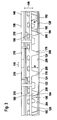
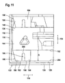
- flat Abtropf Scheme 108th comprises an outer package 110 which is formed as a folding box 112, for example of a corrugated cardboard material or a cardboard material.
- the substantially parallelepiped folding box comprises two vertical long side walls 114 which extend in a longitudinal direction 116 of the package 100, two vertical short side walls 118 which extend in a direction perpendicular to the Extending longitudinally 116 extending horizontal transverse direction 120 of the package 100, a bottom 122, which consists of two foldable on the long side walls 114 of the folding box 112 outer closing tabs 124 (only one of which is shown in the figures) and two on the short side walls 118 of Folding box 112 arranged foldable inner closing tabs 126 (of which in the figures only one half is shown) is formed, and a (not shown) lid, as well as the bottom 122 of the long side walls 114 hingedly arranged outer closing straps and on the short side walls 118 hingedly arranged inner closing tabs is formed.
- FIGS. 1 to 3 support the inner locking tabs 126 in the folded state on the bottom of the inner closing tabs 126 hinged outer locking tabs 124 of the folding box 112 from, but do not extend from the short side walls 118 of the folding box 112 to the middle of the folding box 112, so that between the folded in the state facing each other free edges 128 of the two inner closing tabs 126 of the bottom 122, a gap 130 remains.
- a support assembly for the packaged sink 102 is arranged, which comprises two opposing support body 134, between which the sink 102 is held, wherein in the figures, only one of the two (with respect to the vertical longitudinal center plane of the package 100 mirror-symmetrical to each other trained) supporting body 134 is shown.
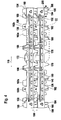
- Each of the two support bodies 134 of the packaging 100 comprises two support elements 136 arranged on one another, namely a receiving element 138 and a spacer element 140, wherein the receiving element 138 rests on the upper side of the spacer element 140 and the receiving element 138 and the spacer element 140 have identical shape and orientation.
- the two support bodies 134 of the packaging 100 thus comprise a total of four support elements 136 of identical shape, namely two receiving elements 138 and two spacer elements 140.
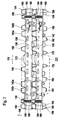
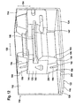
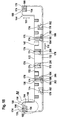
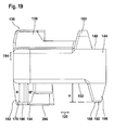
- support members 136 which are formed identically with one another, will be described in detail below using the example of the support element 136 shown individually in FIGS. 14 to 21, which may serve as a receiving element 138 or as a spacer element 140 in the packaging 100.
- the support member 136 is formed as a substantially U-shaped support bar having a central portion 142 extending in the longitudinal direction 116 and two end portions 144 extending along the transverse direction 120.
- the support member 136 is provided with a receiving channel 146 formed by a groove extending approximately centrally in the horizontal direction toward the insides of the central portion 142 and the end portions 144 facing the sink 102.
- This receiving channel 146 is used when receiving the support member 136 as a receiving element 138 for receiving one of the two long edge portions of the sink 102, which is parallel to the two long sides of the sink 102nd extend, and in each case a portion of the two short edge portions which extend along the two short sides of the sink 102.
- the support member 136 used as a receiving member 138 is pushed onto the sink rim, that a long edge portion of the sink edge in the central portion 142 of the receiving channel 146 and parts of the short edge portions of the sink edge in the end portions 144 of the receiving channel 146 engage.
- the sink 102 rests with the underside of the sink rim on the lower boundary wall of the receiving channel 146.
- each support member 136 is provided at its upper surface 148 with a plurality of upper bumps 150, with which the support member 136 is supported when used as a receiving element 138 on the lid of the outer package 110, while when used as a spacer element 140, the receiving element arranged above 138 with its bottom 152 is supported on these upper damping bumps 150.
- the upper cushion bumps 150 taper upwardly from their base located at the top 148 of the body of the support member 136 to have a substantially trapezoidal vertical longitudinal section and to each a transverse, preferably substantially perpendicular to the vertical 154 extending support surface 155 ends.
- the long sides of the upper damping bumps 150 are at the two upper middle damping bumps 156 and at the two upper outer damping bumps 158 which at the transition between the central portion 142 and each one of the end portions 144 of the support member 136 are aligned substantially parallel to the transverse direction 120, while the long sides of the arranged at the end portions 144 upper end damping bumps 160 and the pair in each case between an upper middle damping bump 156 and an upper outer damping bump 158 arranged on the central portion 142 upper intermediate damping bumps 162 are aligned substantially parallel to the longitudinal direction 116.
- Each pair of upper intermediate damping bumps 162 each comprise an outer intermediate damping bump 162a arranged on the outer side of the support element 136 facing away from the sink 102 and an inner intermediate damping bump 162b arranged on the inner side of the support element 136 facing the sink 102.
- the outer intermediate cushion bump 162 a and the respectively associated inner cushion bump 162 b are offset from each other by more than the respective bump widths B, B 'in the transverse direction 120.
- this offset of the intermediate damping bumps 162 relative to each other it is achieved that these damping bumps do not fall into the space between two rollers of a transport roller conveyor which follow each other in a conveying direction when the sink 102 has receiving elements 138 arranged on the sink rim in the head transfer, ie with downward pointing upper damping bumps 150, is conveyed via a transport roller track, in such an orientation that the transverse direction 120 is parallel to the conveying direction of the transport roller conveyor.
- the two intermediate damping humps 162 arranged adjacent to one another are offset from one another by approximately their length L or L 'in the longitudinal direction 116. This offset ensures that the damping bumps 162 do not fall into the space between two successive rolls of the transport roller track when the sink 102 is conveyed in such an orientation over the transport roller track that the longitudinal direction 116 is aligned parallel to the conveying direction of the transport roller track.
- the support element 136 is provided on a side facing away from the sink 102 with two grooves 164, which serve to receive a (not shown) strapping a strapping, through which the support members 136 of the two support body 134 or in the case of a direct stacking of a plurality of rinses 102 explained in more detail below, a plurality of receiving elements 138 of different rinses can be connected to one another.
- the grooves 164 are provided with an optical marker 166 in the form of a square grid, which indicates where on the support member 136, the strapping should extend.
- the optical markings 166 may in particular be formed as a surface profiling, for example as grooves formed in the outer surface of the support element 136.
- the support element 136 is provided on its inside facing the sink 102, for example on the long sides of the inner intermediate damping bumps 162 b, with auxiliary process identification 168 which identifies the associated packaging parts in the packaging process and in FIG facilitate quality assurance.
- These process help tags 168 may be in the form of the letter A, for example.
- the process aid indicia 168 may be formed, for example, as a surface profiling, for example as recesses formed in the surface of the support element 136.
- the support element 136 is provided on its inner side facing the sink 102 in the region of the upper central damping bumps 156, each having a vertical receiving groove 170, which can serve as a vertical holding plate of a basin cover (not shown) of the sink 102, for example of a cardboard plate or a corrugated board may be formed to receive and so the pelvic cover against movement to secure relative to the support member 136 in the longitudinal direction 116, as shown in the EP 1 600 401 A1 is described.
- the support member 136 is provided at its upper side 148 with a stop block 172 disposed between the upper central cushion bumps 156 which can engage a complementary recess on a horizontal cover plate (not shown) of a basin cover to prevent the horizontal cover plate from moving relative to the cover plate Support member 136 in the longitudinal direction 116, as also in the EP 1 600 401 A1 is described.
- the support member 136 is provided on its inside facing the sink 102, in the region between the upper central damping bumps 156 and the upper intermediate damping bumps 162, with two vertical grooves 173, which for receiving a respective projection on a lateral edge of the two support body 134 interconnecting (not shown) can serve intermediate element, as shown in the EP 1 600 401 A1 is described.
- the support element 136 On its underside 152, the support element 136 is likewise provided with a plurality of lower damping bumps 174 which taper downwardly from a base arranged on the underside 152 of the base body of the support element 136 and on each one transverse, preferably substantially perpendicular, to the vertical 154 extending support surface 176 ends.
- the lower damping bumps 174 have a substantially trapezoidal vertical cross-section.
- the long sides of the two lower central damping bumps 178 extend substantially parallel to the transverse direction 120.
- a lower intermediate damping bump 180 and a lower outer damping bump 182 follow each other on both sides of the lower middle damping bumps 178.
- Each of the lower intermediate damping bumps 180 comprises an inner portion 184, whose long sides are oriented substantially parallel to the transverse direction 120, and a shorter outer portion 186 immediately adjacent to the inner portion 184, the long sides of which are aligned substantially parallel to the longitudinal direction 116.
- Each of the lower outer damping bumps 182 is formed in an angular shape and thus extends in sections parallel to the longitudinal direction 116 and partially parallel to the transverse direction 120.
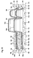
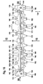
- a multi-stage damping bump group 188 is arranged, which as the first damping step a high damping hump 190 whose support surface 192 at rest H of the support member 136 (measured from the bottom 152 of the strip-shaped base body of the support member 136 from ), and as a second damping stage, a low damping hump 194, the support surface 196 in the resting state of the support member 136 at the height h, ie closer to the bottom 152 of the body of the Support member 136, from which extend the lower damping bumps 174 downwards, is located.
- the tips of the high damping bump 190 and the low damping bump 194 are separated by a gap 198 disposed between the two damping bumps and extending substantially parallel to the transverse direction 120 which decouples the two damping bumps 190, 194 so that the material of the high damping bump 190 can be deformed in the initial phase of a shock stress, without being hindered by a coupling to the material of the low damping bump 194.
- the gap 198 extends, starting from the support surface 196 of the low damper bump 194, by at least the height h / 2, preferably by approximately 70% of the height h, towards the bottom 152 of the base body of the support member 136.
- the bumps 190, 194 of the bump group 188 are interconnected by a common bump pad 200.
- the higher damping hump 190 is preferably located further from the center of the support member 136 than the lower damping hump 194 of the damping bump group 188.
- the support surfaces 192 of the high damper bumps 190 of the damper bump groups 188 are the support surfaces 176 of the lower outer damping bumps 182 and the support surfaces 202 of the outer portions 186 of the lower intermediate damping bumps 180, which are all at the same height H (measured from the underside 152 of the strip-shaped base of the support member 136), all at the interior of the 132 Umverpackung 110 facing top 204 of the respective associated inner closing tab 126 flat.
- the lower central damping bumps 178 and the inner portions 184 of the lower intermediate damping bumps 180 extend into the space 130 between the free edges 128 of the inner closure tabs 126 so that the support surfaces 206 of the lower middle damping bumps 178 and inner portions 184 of FIG lower intermediate damping bumps 180, which are all at the same height H '(as measured from the underside 152 of the strip-shaped base of the support member 136) farther from the bottom 152 of the support member 136 than the height H of the high damping bump support surface 192 190 of the damping bump groups 188 and the support surfaces 178 of the lower outer damping bumps 182, in the resting state of the package 100 lie flat against the upper surface 208 of one of the outer closing latches 124 of the folding box 112.
- the difference between the heights H on the one hand and H 'on the other hand corresponds to the thickness of the inner closing tabs 126, which corresponds to the material thickness of the folding box 112 of, for example, approximately 7 mm.
- the possible deflection of the packaged sink 102 is effectively reduced, especially in the particularly fracture-prone middle region of the sink, and thus the risk of breakage of the sink, in particular a sink made of a composite material, is considerably reduced in this area.
- recesses or depressions 210 are provided on the upper surface 148 of the support member 136 just vertically above the lower central damping bumps 178,180 formed to be complementary to the tips of the lower middle damping bumps 178 and the inner portions 184 of the lower intermediate damping bumps 180, respectively, and whose depth substantially matches the difference between the heights H and H 'of the lower damping bumps 174 so that all the lower damping bumps 174 flat against the top 148 of the lower, serving as a spacer member 140 support member 136 when another, serving as a receiving element 138 support member 136 is placed from above on this lower support member 136.
- the support elements 136 are preferably formed from a foamed plastic material, in particular from an expanded polystyrene material.
- the support elements 136 are further preferably each formed in one piece.
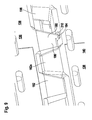
- the reaction force of the support element 136 is thus specifically reduced in this first damping stage in the end region of the support element 136, where the forces acting on the longest lever with respect to the particularly fracture-prone central region of the packaged sink 102, thereby causing the sink 102 at low drop heights with a lower deflection in the receiving channel 146 of the damping receiving element 138 dips.
- this lower deflection in the first damping stage the risk of breakage of the sink, in particular a sink made of a composite material, in the particularly fracture-prone middle region of the sink is considerably reduced (see FIG. 10).
- This second, harder cushioning stage benefits from the fact that the edge region of the packaged sink 102 in the first cushioning stage is more evenly submerged in the receiving channel 146 of the receiving member 138.
- the support elements 136 serving as receiving elements 138 of the above-described packaging 100 can be stacked directly on one another, the same receiving elements 138 can be used instead of for individual packaging a sink 102 in an outer package 110 can also be used to produce a stack 212 of rinses 102, as shown in FIG.
- two receiving elements 138 which are formed just like the support elements 136 described above, are pushed onto the edge sections of the rinsing edge of a first rinse 102a, so that these edge sections are received in the receiving channels 146 of the first receiving elements 138a ,
- the first receiving elements 138a can be fixed by means of a strapping of a strip material to the sink 102a.
- a second sink 102b is provided in the same way with second receiving elements 138b, which are identical to the first receiving elements 138a.
- These second receiving elements 138b can be fixed by means of a strapping of a strip material to the second sink 102b.
- the first sink 102a is placed on a base 214 in the head-facing, ie with downwardly facing pelvic openings, wherein the upper damping bumps 150 at the (in this position downwardly facing) top 148 of the first receiving elements 138a, the support surfaces 155 all the same Height, ie the same distance from the upper surface 148 of the strip-shaped main body of the receiving elements 138 a, are supported on the substrate 214 and the two first receiving elements 138 a carry the first sink 102 a, without the same touches the substrate 214.
- the second sink 102b is also placed in the head transfer, with the second receiving elements 138b on the first sink 102a, in such a way that the (in this position, facing downwards) upper damping bumps 150 of the second receiving elements 138b on the (in this position facing up) underside 152 of the first receiving elements 138a abut (and in this position upwardly facing) lower damping bumps 174 of the first receiving elements 138a flat against the (in this position facing down) top 148 of the second receiving elements 138b or engage in the recesses 210 at the top 148 of the second receiving elements 138b.
- the rinses 102 can be arranged in a particularly space-saving manner and stored in this arrangement, for example, before a single transport in an outer package 110.
- the rinses 102 stored in the stack 212 can be individually wrapped in a respective outer packaging without prior removal of the receiving elements 138 and thus particularly time-saving 100, so that the number of packaging elements required for storage in the stack 212 and for the subsequent individual packaging of the rinses 102 in each packaging 100 is reduced.
- a sink 102 with receiving elements 138 arranged thereon in the head transfer is also particularly suitable for transporting the sink 102 via a transport roller conveyor with transport rollers following one another in a conveying direction, which are rotatable about horizontal axes oriented perpendicular to the conveying direction.
- the sink 102 is turned off in the head-up with the receiving elements 138 on the transport roller track that the (in the head presentation facing down) upper damping bumps 150 rest on the upper crests of the transport rollers.
Landscapes
- Engineering & Computer Science (AREA)
- Mechanical Engineering (AREA)
- Buffer Packaging (AREA)
- Basic Packing Technique (AREA)
Applications Claiming Priority (1)
| Application Number | Priority Date | Filing Date | Title |
|---|---|---|---|
| DE102006021179A DE102006021179A1 (de) | 2006-05-06 | 2006-05-06 | Verpackung für ein Transportgut |
Publications (3)
| Publication Number | Publication Date |
|---|---|
| EP1880950A2 true EP1880950A2 (fr) | 2008-01-23 |
| EP1880950A3 EP1880950A3 (fr) | 2009-05-27 |
| EP1880950B1 EP1880950B1 (fr) | 2010-07-21 |
Family
ID=38564929
Family Applications (1)
| Application Number | Title | Priority Date | Filing Date |
|---|---|---|---|
| EP07004969A Not-in-force EP1880950B1 (fr) | 2006-05-06 | 2007-03-10 | Emballage pour un produit de transport |
Country Status (3)
| Country | Link |
|---|---|
| EP (1) | EP1880950B1 (fr) |
| AT (1) | ATE474776T1 (fr) |
| DE (2) | DE102006021179A1 (fr) |
Families Citing this family (3)
| Publication number | Priority date | Publication date | Assignee | Title |
|---|---|---|---|---|
| EP2208683B1 (fr) * | 2009-01-14 | 2011-11-02 | BLANCO GmbH + Co KG | Emballage pour un évier |
| DE102013019661A1 (de) * | 2013-11-19 | 2015-05-21 | Schock Gmbh | Beckentransporteinheit, insbesondere Spülbeckentransporteinheit |
| DE102022201516A1 (de) * | 2022-02-14 | 2023-08-17 | Blanco Gmbh + Co Kg | Verpackungssystem für ein Transportgut |
Family Cites Families (6)
| Publication number | Priority date | Publication date | Assignee | Title |
|---|---|---|---|---|
| IT1077140B (it) * | 1977-02-17 | 1985-05-04 | Eurodomestici Ind Riunite | Imballaggio per oggetti in forma di un parallelepipedo o di un cubo,particolarmente per apparecchi domestici |
| DE2845703C2 (de) * | 1978-10-20 | 1985-09-05 | Werzalit-Werke J.F. Werz KG, 7141 Oberstenfeld | Einstückiger Einzelverpackungsuntersatz |
| KR0116756Y1 (ko) * | 1995-07-31 | 1998-04-24 | 구자홍 | 종이재질의 전자제품 포장용 완충재 구조 |
| JP2000085848A (ja) * | 1998-09-14 | 2000-03-28 | Sony Corp | 包装箱用クッション |
| US7240792B2 (en) * | 2004-05-29 | 2007-07-10 | Blanco Gmbh + Co Kg | Packaging for a sink |
| EP1600401A1 (fr) * | 2004-05-29 | 2005-11-30 | BLANCO GmbH + Co KG | Emballage pour un évier |
-
2006
- 2006-05-06 DE DE102006021179A patent/DE102006021179A1/de not_active Withdrawn
-
2007
- 2007-03-10 EP EP07004969A patent/EP1880950B1/fr not_active Not-in-force
- 2007-03-10 AT AT07004969T patent/ATE474776T1/de active
- 2007-03-10 DE DE502007004453T patent/DE502007004453D1/de active Active
Also Published As
| Publication number | Publication date |
|---|---|
| EP1880950B1 (fr) | 2010-07-21 |
| EP1880950A3 (fr) | 2009-05-27 |
| DE502007004453D1 (de) | 2010-09-02 |
| DE102006021179A1 (de) | 2007-11-08 |
| ATE474776T1 (de) | 2010-08-15 |
Similar Documents
| Publication | Publication Date | Title |
|---|---|---|
| DE69028719T2 (de) | Wellpappe-palette | |
| DE69103699T2 (de) | Kasten zur Aufnahme von Flaschen. | |
| EP2320157B1 (fr) | Fixation et système d'empilement modulaire pour la fixation et/ou le transport sécurisé de modules PV sans cadre ou d'autres corps plats parallélépipédiques | |
| EP3608257A1 (fr) | Système d'emballage pour une marchandise à transporter et procédé d'emballage d'une marchandise à transporter | |
| EP1880950B1 (fr) | Emballage pour un produit de transport | |
| EP1710179A1 (fr) | Magasin pour piles de caisses | |
| EP2497727A2 (fr) | Tablette dotée d'un support pliable | |
| EP3009366B1 (fr) | Conteneur | |
| EP1852358A1 (fr) | Emballage pour produits de transport | |
| EP1600403B1 (fr) | Conditionnement pour un évier | |
| EP1651533B1 (fr) | Cageot a plusieurs cavites | |
| EP1222043A1 (fr) | Procede de fabrication d'ensembles lamellaires pour colonnes de direction reglables | |
| EP3406541B1 (fr) | Emballage pour objets | |
| DE19948124A1 (de) | Zerlegbare Stapelkiste | |
| DE69602282T2 (de) | Palettiersystem mit streifenförmigen verstärkungen gegen druckkräfte | |
| DE102013104883A1 (de) | Ständer zum Aufbewahren von plattenförmigen Gegenständen | |
| EP3601077B1 (fr) | Casier de stockage empilable | |
| EP3543158B1 (fr) | Conteneur de transport | |
| EP2036827B1 (fr) | Portoir de module superposable | |
| DE202017100415U1 (de) | Faltbare Transport- und Lagerungsvorrichtung | |
| EP1842779B1 (fr) | Emballage pour un produit de transport | |
| EP3702293A1 (fr) | Insert pliable pour récipients | |
| EP0330208B1 (fr) | Casier | |
| DE202012002496U1 (de) | Verpackung und Zuschnitt hierfür | |
| DE10354538B4 (de) | Transportbehälter |
Legal Events
| Date | Code | Title | Description |
|---|---|---|---|
| PUAI | Public reference made under article 153(3) epc to a published international application that has entered the european phase |
Free format text: ORIGINAL CODE: 0009012 |
|
| AK | Designated contracting states |
Kind code of ref document: A2 Designated state(s): AT BE BG CH CY CZ DE DK EE ES FI FR GB GR HU IE IS IT LI LT LU LV MC MT NL PL PT RO SE SI SK TR |
|
| AX | Request for extension of the european patent |
Extension state: AL BA HR MK YU |
|
| PUAL | Search report despatched |
Free format text: ORIGINAL CODE: 0009013 |
|
| AK | Designated contracting states |
Kind code of ref document: A3 Designated state(s): AT BE BG CH CY CZ DE DK EE ES FI FR GB GR HU IE IS IT LI LT LU LV MC MT NL PL PT RO SE SI SK TR |
|
| AX | Request for extension of the european patent |
Extension state: AL BA HR MK RS |
|
| 17P | Request for examination filed |
Effective date: 20091103 |
|
| AKX | Designation fees paid |
Designated state(s): AT BE BG CH CY CZ DE DK EE ES FI FR GB GR HU IE IS IT LI LT LU LV MC MT NL PL PT RO SE SI SK TR |
|
| GRAP | Despatch of communication of intention to grant a patent |
Free format text: ORIGINAL CODE: EPIDOSNIGR1 |
|
| RIN1 | Information on inventor provided before grant (corrected) |
Inventor name: REITZIG, WOLFGANG |
|
| GRAS | Grant fee paid |
Free format text: ORIGINAL CODE: EPIDOSNIGR3 |
|
| GRAA | (expected) grant |
Free format text: ORIGINAL CODE: 0009210 |
|
| AK | Designated contracting states |
Kind code of ref document: B1 Designated state(s): AT BE BG CH CY CZ DE DK EE ES FI FR GB GR HU IE IS IT LI LT LU LV MC MT NL PL PT RO SE SI SK TR |
|
| REG | Reference to a national code |
Ref country code: GB Ref legal event code: FG4D Free format text: NOT ENGLISH |
|
| REG | Reference to a national code |
Ref country code: CH Ref legal event code: EP |
|
| REG | Reference to a national code |
Ref country code: IE Ref legal event code: FG4D |
|
| REF | Corresponds to: |
Ref document number: 502007004453 Country of ref document: DE Date of ref document: 20100902 Kind code of ref document: P |
|
| REG | Reference to a national code |
Ref country code: NL Ref legal event code: VDEP Effective date: 20100721 |
|
| LTIE | Lt: invalidation of european patent or patent extension |
Effective date: 20100721 |
|
| PG25 | Lapsed in a contracting state [announced via postgrant information from national office to epo] |
Ref country code: NL Free format text: LAPSE BECAUSE OF FAILURE TO SUBMIT A TRANSLATION OF THE DESCRIPTION OR TO PAY THE FEE WITHIN THE PRESCRIBED TIME-LIMIT Effective date: 20100721 Ref country code: FI Free format text: LAPSE BECAUSE OF FAILURE TO SUBMIT A TRANSLATION OF THE DESCRIPTION OR TO PAY THE FEE WITHIN THE PRESCRIBED TIME-LIMIT Effective date: 20100721 Ref country code: LT Free format text: LAPSE BECAUSE OF FAILURE TO SUBMIT A TRANSLATION OF THE DESCRIPTION OR TO PAY THE FEE WITHIN THE PRESCRIBED TIME-LIMIT Effective date: 20100721 |
|
| REG | Reference to a national code |
Ref country code: IE Ref legal event code: FD4D |
|
| PG25 | Lapsed in a contracting state [announced via postgrant information from national office to epo] |
Ref country code: IS Free format text: LAPSE BECAUSE OF FAILURE TO SUBMIT A TRANSLATION OF THE DESCRIPTION OR TO PAY THE FEE WITHIN THE PRESCRIBED TIME-LIMIT Effective date: 20101121 Ref country code: BG Free format text: LAPSE BECAUSE OF FAILURE TO SUBMIT A TRANSLATION OF THE DESCRIPTION OR TO PAY THE FEE WITHIN THE PRESCRIBED TIME-LIMIT Effective date: 20101021 Ref country code: CY Free format text: LAPSE BECAUSE OF FAILURE TO SUBMIT A TRANSLATION OF THE DESCRIPTION OR TO PAY THE FEE WITHIN THE PRESCRIBED TIME-LIMIT Effective date: 20100721 Ref country code: PL Free format text: LAPSE BECAUSE OF FAILURE TO SUBMIT A TRANSLATION OF THE DESCRIPTION OR TO PAY THE FEE WITHIN THE PRESCRIBED TIME-LIMIT Effective date: 20100721 Ref country code: PT Free format text: LAPSE BECAUSE OF FAILURE TO SUBMIT A TRANSLATION OF THE DESCRIPTION OR TO PAY THE FEE WITHIN THE PRESCRIBED TIME-LIMIT Effective date: 20101122 Ref country code: SI Free format text: LAPSE BECAUSE OF FAILURE TO SUBMIT A TRANSLATION OF THE DESCRIPTION OR TO PAY THE FEE WITHIN THE PRESCRIBED TIME-LIMIT Effective date: 20100721 |
|
| PG25 | Lapsed in a contracting state [announced via postgrant information from national office to epo] |
Ref country code: LV Free format text: LAPSE BECAUSE OF FAILURE TO SUBMIT A TRANSLATION OF THE DESCRIPTION OR TO PAY THE FEE WITHIN THE PRESCRIBED TIME-LIMIT Effective date: 20100721 Ref country code: SE Free format text: LAPSE BECAUSE OF FAILURE TO SUBMIT A TRANSLATION OF THE DESCRIPTION OR TO PAY THE FEE WITHIN THE PRESCRIBED TIME-LIMIT Effective date: 20100721 Ref country code: GR Free format text: LAPSE BECAUSE OF FAILURE TO SUBMIT A TRANSLATION OF THE DESCRIPTION OR TO PAY THE FEE WITHIN THE PRESCRIBED TIME-LIMIT Effective date: 20101022 |
|
| PG25 | Lapsed in a contracting state [announced via postgrant information from national office to epo] |
Ref country code: IE Free format text: LAPSE BECAUSE OF FAILURE TO SUBMIT A TRANSLATION OF THE DESCRIPTION OR TO PAY THE FEE WITHIN THE PRESCRIBED TIME-LIMIT Effective date: 20100721 Ref country code: DK Free format text: LAPSE BECAUSE OF FAILURE TO SUBMIT A TRANSLATION OF THE DESCRIPTION OR TO PAY THE FEE WITHIN THE PRESCRIBED TIME-LIMIT Effective date: 20100721 |
|
| PLBE | No opposition filed within time limit |
Free format text: ORIGINAL CODE: 0009261 |
|
| STAA | Information on the status of an ep patent application or granted ep patent |
Free format text: STATUS: NO OPPOSITION FILED WITHIN TIME LIMIT |
|
| PG25 | Lapsed in a contracting state [announced via postgrant information from national office to epo] |
Ref country code: RO Free format text: LAPSE BECAUSE OF FAILURE TO SUBMIT A TRANSLATION OF THE DESCRIPTION OR TO PAY THE FEE WITHIN THE PRESCRIBED TIME-LIMIT Effective date: 20100721 Ref country code: EE Free format text: LAPSE BECAUSE OF FAILURE TO SUBMIT A TRANSLATION OF THE DESCRIPTION OR TO PAY THE FEE WITHIN THE PRESCRIBED TIME-LIMIT Effective date: 20100721 Ref country code: SK Free format text: LAPSE BECAUSE OF FAILURE TO SUBMIT A TRANSLATION OF THE DESCRIPTION OR TO PAY THE FEE WITHIN THE PRESCRIBED TIME-LIMIT Effective date: 20100721 Ref country code: CZ Free format text: LAPSE BECAUSE OF FAILURE TO SUBMIT A TRANSLATION OF THE DESCRIPTION OR TO PAY THE FEE WITHIN THE PRESCRIBED TIME-LIMIT Effective date: 20100721 Ref country code: IT Free format text: LAPSE BECAUSE OF FAILURE TO SUBMIT A TRANSLATION OF THE DESCRIPTION OR TO PAY THE FEE WITHIN THE PRESCRIBED TIME-LIMIT Effective date: 20100721 |
|
| 26N | No opposition filed |
Effective date: 20110426 |
|
| PG25 | Lapsed in a contracting state [announced via postgrant information from national office to epo] |
Ref country code: ES Free format text: LAPSE BECAUSE OF FAILURE TO SUBMIT A TRANSLATION OF THE DESCRIPTION OR TO PAY THE FEE WITHIN THE PRESCRIBED TIME-LIMIT Effective date: 20101101 |
|
| REG | Reference to a national code |
Ref country code: DE Ref legal event code: R097 Ref document number: 502007004453 Country of ref document: DE Effective date: 20110426 |
|
| BERE | Be: lapsed |
Owner name: BLANCO G.M.B.H. + CO KG Effective date: 20110331 |
|
| PG25 | Lapsed in a contracting state [announced via postgrant information from national office to epo] |
Ref country code: MC Free format text: LAPSE BECAUSE OF NON-PAYMENT OF DUE FEES Effective date: 20110331 |
|
| REG | Reference to a national code |
Ref country code: CH Ref legal event code: PL |
|
| PG25 | Lapsed in a contracting state [announced via postgrant information from national office to epo] |
Ref country code: BE Free format text: LAPSE BECAUSE OF NON-PAYMENT OF DUE FEES Effective date: 20110331 Ref country code: MT Free format text: LAPSE BECAUSE OF FAILURE TO SUBMIT A TRANSLATION OF THE DESCRIPTION OR TO PAY THE FEE WITHIN THE PRESCRIBED TIME-LIMIT Effective date: 20100721 |
|
| PG25 | Lapsed in a contracting state [announced via postgrant information from national office to epo] |
Ref country code: CH Free format text: LAPSE BECAUSE OF NON-PAYMENT OF DUE FEES Effective date: 20110331 Ref country code: LI Free format text: LAPSE BECAUSE OF NON-PAYMENT OF DUE FEES Effective date: 20110331 |
|
| REG | Reference to a national code |
Ref country code: AT Ref legal event code: MM01 Ref document number: 474776 Country of ref document: AT Kind code of ref document: T Effective date: 20120310 |
|
| PG25 | Lapsed in a contracting state [announced via postgrant information from national office to epo] |
Ref country code: LU Free format text: LAPSE BECAUSE OF NON-PAYMENT OF DUE FEES Effective date: 20110310 |
|
| PG25 | Lapsed in a contracting state [announced via postgrant information from national office to epo] |
Ref country code: AT Free format text: LAPSE BECAUSE OF NON-PAYMENT OF DUE FEES Effective date: 20120310 |
|
| PG25 | Lapsed in a contracting state [announced via postgrant information from national office to epo] |
Ref country code: TR Free format text: LAPSE BECAUSE OF FAILURE TO SUBMIT A TRANSLATION OF THE DESCRIPTION OR TO PAY THE FEE WITHIN THE PRESCRIBED TIME-LIMIT Effective date: 20100721 |
|
| PG25 | Lapsed in a contracting state [announced via postgrant information from national office to epo] |
Ref country code: HU Free format text: LAPSE BECAUSE OF FAILURE TO SUBMIT A TRANSLATION OF THE DESCRIPTION OR TO PAY THE FEE WITHIN THE PRESCRIBED TIME-LIMIT Effective date: 20100721 |
|
| REG | Reference to a national code |
Ref country code: FR Ref legal event code: PLFP Year of fee payment: 9 |
|
| PGFP | Annual fee paid to national office [announced via postgrant information from national office to epo] |
Ref country code: FR Payment date: 20150309 Year of fee payment: 9 Ref country code: GB Payment date: 20150304 Year of fee payment: 9 |
|
| REG | Reference to a national code |
Ref country code: DE Ref legal event code: R082 Ref document number: 502007004453 Country of ref document: DE Representative=s name: HOEGER, STELLRECHT & PARTNER PATENTANWAELTE MB, DE |
|
| PGFP | Annual fee paid to national office [announced via postgrant information from national office to epo] |
Ref country code: DE Payment date: 20150429 Year of fee payment: 9 |
|
| REG | Reference to a national code |
Ref country code: DE Ref legal event code: R119 Ref document number: 502007004453 Country of ref document: DE |
|
| GBPC | Gb: european patent ceased through non-payment of renewal fee |
Effective date: 20160310 |
|
| REG | Reference to a national code |
Ref country code: FR Ref legal event code: ST Effective date: 20161130 |
|
| PG25 | Lapsed in a contracting state [announced via postgrant information from national office to epo] |
Ref country code: DE Free format text: LAPSE BECAUSE OF NON-PAYMENT OF DUE FEES Effective date: 20161001 Ref country code: GB Free format text: LAPSE BECAUSE OF NON-PAYMENT OF DUE FEES Effective date: 20160310 Ref country code: FR Free format text: LAPSE BECAUSE OF NON-PAYMENT OF DUE FEES Effective date: 20160331 |