EP1880975A1 - Installation de distribution de fluide pour un atelier - Google Patents
Installation de distribution de fluide pour un atelier Download PDFInfo
- Publication number
- EP1880975A1 EP1880975A1 EP06425492A EP06425492A EP1880975A1 EP 1880975 A1 EP1880975 A1 EP 1880975A1 EP 06425492 A EP06425492 A EP 06425492A EP 06425492 A EP06425492 A EP 06425492A EP 1880975 A1 EP1880975 A1 EP 1880975A1
- Authority
- EP
- European Patent Office
- Prior art keywords
- plant
- flow rate
- fluid
- pressure
- valve
- Prior art date
- Legal status (The legal status is an assumption and is not a legal conclusion. Google has not performed a legal analysis and makes no representation as to the accuracy of the status listed.)
- Withdrawn
Links
- 239000012530 fluid Substances 0.000 title claims abstract description 102
- 238000005086 pumping Methods 0.000 claims abstract description 42
- 238000006073 displacement reaction Methods 0.000 claims description 21
- 230000001105 regulatory effect Effects 0.000 claims description 11
- 238000010586 diagram Methods 0.000 claims description 6
- IJGRMHOSHXDMSA-UHFFFAOYSA-N Atomic nitrogen Chemical compound N#N IJGRMHOSHXDMSA-UHFFFAOYSA-N 0.000 description 4
- 239000007788 liquid Substances 0.000 description 4
- 230000036316 preload Effects 0.000 description 3
- 238000009825 accumulation Methods 0.000 description 2
- 230000008901 benefit Effects 0.000 description 2
- 230000006835 compression Effects 0.000 description 2
- 238000007906 compression Methods 0.000 description 2
- 230000001276 controlling effect Effects 0.000 description 2
- 230000000670 limiting effect Effects 0.000 description 2
- 239000012528 membrane Substances 0.000 description 2
- 238000000034 method Methods 0.000 description 2
- 229910052757 nitrogen Inorganic materials 0.000 description 2
- 230000008569 process Effects 0.000 description 2
- 230000002411 adverse Effects 0.000 description 1
- 230000000712 assembly Effects 0.000 description 1
- 238000000429 assembly Methods 0.000 description 1
- 230000015572 biosynthetic process Effects 0.000 description 1
- 230000008859 change Effects 0.000 description 1
- 230000003247 decreasing effect Effects 0.000 description 1
- 238000005265 energy consumption Methods 0.000 description 1
- 238000009313 farming Methods 0.000 description 1
- 239000007789 gas Substances 0.000 description 1
- 230000002401 inhibitory effect Effects 0.000 description 1
- 238000009434 installation Methods 0.000 description 1
- 239000000314 lubricant Substances 0.000 description 1
- 238000004519 manufacturing process Methods 0.000 description 1
- 230000007246 mechanism Effects 0.000 description 1
- 230000010349 pulsation Effects 0.000 description 1
- 230000008439 repair process Effects 0.000 description 1
- 238000010998 test method Methods 0.000 description 1
- 238000011144 upstream manufacturing Methods 0.000 description 1
Images


Classifications
-
- G—PHYSICS
- G05—CONTROLLING; REGULATING
- G05D—SYSTEMS FOR CONTROLLING OR REGULATING NON-ELECTRIC VARIABLES
- G05D7/00—Control of flow
- G05D7/06—Control of flow characterised by the use of electric means
- G05D7/0617—Control of flow characterised by the use of electric means specially adapted for fluid materials
- G05D7/0629—Control of flow characterised by the use of electric means specially adapted for fluid materials characterised by the type of regulator means
- G05D7/0688—Control of flow characterised by the use of electric means specially adapted for fluid materials characterised by the type of regulator means by combined action on throttling means and flow sources
-
- B—PERFORMING OPERATIONS; TRANSPORTING
- B67—OPENING, CLOSING OR CLEANING BOTTLES, JARS OR SIMILAR CONTAINERS; LIQUID HANDLING
- B67D—DISPENSING, DELIVERING OR TRANSFERRING LIQUIDS, NOT OTHERWISE PROVIDED FOR
- B67D7/00—Apparatus or devices for transferring liquids from bulk storage containers or reservoirs into vehicles or into portable containers, e.g. for retail sale purposes
- B67D7/04—Apparatus or devices for transferring liquids from bulk storage containers or reservoirs into vehicles or into portable containers, e.g. for retail sale purposes for transferring fuels, lubricants or mixed fuels and lubricants
-
- B—PERFORMING OPERATIONS; TRANSPORTING
- B67—OPENING, CLOSING OR CLEANING BOTTLES, JARS OR SIMILAR CONTAINERS; LIQUID HANDLING
- B67D—DISPENSING, DELIVERING OR TRANSFERRING LIQUIDS, NOT OTHERWISE PROVIDED FOR
- B67D7/00—Apparatus or devices for transferring liquids from bulk storage containers or reservoirs into vehicles or into portable containers, e.g. for retail sale purposes
- B67D7/06—Details or accessories
- B67D7/08—Arrangements of devices for controlling, indicating, metering or registering quantity or price of liquid transferred
-
- B—PERFORMING OPERATIONS; TRANSPORTING
- B67—OPENING, CLOSING OR CLEANING BOTTLES, JARS OR SIMILAR CONTAINERS; LIQUID HANDLING
- B67D—DISPENSING, DELIVERING OR TRANSFERRING LIQUIDS, NOT OTHERWISE PROVIDED FOR
- B67D7/00—Apparatus or devices for transferring liquids from bulk storage containers or reservoirs into vehicles or into portable containers, e.g. for retail sale purposes
- B67D7/06—Details or accessories
- B67D7/36—Arrangements of flow- or pressure-control valves
-
- B—PERFORMING OPERATIONS; TRANSPORTING
- B67—OPENING, CLOSING OR CLEANING BOTTLES, JARS OR SIMILAR CONTAINERS; LIQUID HANDLING
- B67D—DISPENSING, DELIVERING OR TRANSFERRING LIQUIDS, NOT OTHERWISE PROVIDED FOR
- B67D7/00—Apparatus or devices for transferring liquids from bulk storage containers or reservoirs into vehicles or into portable containers, e.g. for retail sale purposes
- B67D7/06—Details or accessories
- B67D7/42—Filling nozzles
Definitions
- the present invention relates to a workshop fluid distribution plant.
- the present invention finds advantageous, but not exclusive, application in a mechanical car repair workshop, to which explicit reference will be made in the description that follows without for this loosing in generality.
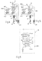
- number 10 generically shows as a whole a possible traditional distribution plant of at least one fluid in a car workshop.
- plant 10 comprises two equivalent hydraulic circuits C1, C2 for distributing two generally reciprocally different fluids FL1, FL2 respectively, to three fixed stations P1, P2, P3.
- hydraulic circuit C1 hydraulic circuit C2 is also described.
- a tank SB for stocking a first fluid FL1 e.g. lubricant oil
- a pumping system SP hydraulically connected to the fluid distribution hydraulic circuit C1 towards a first series of users U1', U1", U1"' belonging to a respective fixed station P1, P2, P3 may be recognised.
- Pumping system SP is connected in suction to a suction tube TP immersed in fluid FL1 and in delivery to hydraulic circuit C1 by means of a manual valve VM.
- pumping system SP is managed by an electrical panel EQ which monitors the presence of fluid FL1 in tank SB by means of a level gauge LV and communicates with an electronic control system EG for inhibiting the dispensing of fluid FL1 when it is about to finish.
- a control unit UG1, UG2, UG3 for each respective fixed position P1, P2, P3, combined with a dedicated PC CC, constitutes the aforesaid electronic control system EG of the entire system 10.
- Each user U1', U1", U1"' is connected to hydraulic fluid distribution circuit C1 by means of a manual valve 11 (figure 1).
- each user U1', U1", U1"' comprises a volume counter 12 and a solenoid valve 13 (normally closed) to shut off the flow of fluid FL1.
- volume counter 12 and solenoid valve 13 are electronically connected to control unit UG1 which governs the dispensing of fluid FL1 to fixed station P1.
- the drawing of fluid FL1 is guaranteed by a mechanical reel 14 for a flexible tube 14 ending with a dispensing gun 16.
- Solenoid valve 13 is normally in "closed” position (shown in figure 1).
- control unit UG1 records the quantity of dispensed fluid by means of volume counter 12.
- plant 10 belonging to the prior art as that shown in figure 1 with the types of pump commonly used manifests several problems related to the dispensing of fluid FL1.
- the main problems noticed using a pumping system based on a pneumatic piston pump include:
- the innovative plant solution which will be described below is based on a system capable of selecting the flow rate of each single user, so as to never exceed the set value.
- a distribution plant for at least one fluid in a workshop is therefore made according to the present invention and to the accompanying claims.
- the components used in making the dispensing point may be considered as fixed bottlenecks which limit the flow of the fluid. Therefore, in order to ensure a certain flow rate from a dispensing point, a pressure adapted to overcome the loss of distributed load attributed to the distributing pipe, plus the concentrated loss of loads attributed to the single components (valves, volume counters, reel, dispensing gun) must be applied to the fluid. Conversely, in equivalent running conditions, the dispensed flow rate will vary according to the length of the system, the type of fluid and its viscosity related to temperature.
- a first possible improving intervention consists in inserting, before each drawing point, at least one "Compensated Flow Regulating Valve” (hereinafter abbreviated as CFRV).
- CFRV Computerpensated Flow Regulating Valve
- Figures 2, 3 show two types of CFRV, one with flow rate adjustable by means of a knob and the other with fixed flow rate, respectively.
- the CFRV valve behaves as a variable bottleneck which, inserted in a hydraulic circuit, allows to limit the flow to a predetermined value. Practically, the fluid crosses a bottleneck which produces a pressure drop between an input point A and an output point B proportional to the flow rate squared; the pressure P A pushes a shutter which tends to further close the passage, while pressure P B , combined with a calibration spring, is opposed to the shift of the shutter, thus "compensating" the thrust of P A . The force of the spring determines the value ⁇ P AB over which the valve intervenes and flow rate is limited.
- a knob is used to vary the force of the spring, thus allowing to change the maximum flow rate of the CFRV valve, while in the fixed flow rate version (figure 3), the spring is calibrated by the manufacturer and the setting cannot be changed (there are various models for different flow rates); the latter version appears as a "cartridge valve" to be inserted in a common internal threaded union.
- FIGS 4, 5, 6 show some examples of application of the valves just described.
- a valve system using at least two CFRVs may be easily installed upstream of the dispensing components, allowing to operate with high fluid pressures, ensuring that the flow rate set by the valve is never exceeded.
- An intermediate flow rate (e.g. 4 1/min) may be envisaged and however, given the type of use, the need to have more than three different calibration values is not felt.
- figure 4 shows a first adjustment system SR1 of the flow rate of fluid FL1, consisting of a plurality of valves VL1, VL2, EV1, EV2, arranged according to a hydraulic diagram.
- valve EV1 in series to VL1, with EV2 closed, the flow rate of the fluid being distributed is minimum, e.g. 2 1/min.
- valve EV1 is closed and valve EV2 is opened, the latter in series with VL2, there is a medium flow rate of 4 1/min to dispensing gun 16.
- valves VL1 and VL2 are two CFRVs (figures 2, 3), while valves EV1, EV2, are solenoid valves of the "normally closed" type.
- the flow rate is set by the operator by means of a flow rate selector 18 (figure 4) which controls the opening of either EV1, or EV2, or both.
- a system SR1 has been added (comprising valves VL1, VL2, EV1, EV2), which is arranged downstream of solenoid valve 13 of the "normally closed” type, to the traditional system shown in figure 1.
- system SR1 integrates volume counter 12 forming a second system SR2, in which solenoid valves EV1, EV2, are directly controlled by control unit UG1.
- valve assembly VL1, VL2, EV1, EV2, used to determine the maximum flow rate in systems SR1, SR2, a "proportioning flow rate regulating valve" may be used.
- the flow rate may be selected either directly on the control unit UG1, or by means of a rotational selector with "n" positions (not shown).
- a third system SR3 may be installed directly within the dispensing gun 16.
- system SR3 comprises two valves VLmax, VLmin (both of the CFRV type), between which a distributor DB (of the 3/3 type) is positioned.
- the valve VLmax is the one allowing maximum flow rate (e.g. 6 1/min) and will be in all cases crossed by fluid.
- Distributor DB positioned downstream of the VLmax valve is operated manually by an operator by means of a lever LV of distributing gun 16.
- Distributor DB is normally closed and therefore home position envisages the block of the flow rate through dispensing gun 16 (configuration shown in figure 6).
- valve VLmin is characterised by a lower plate rating and thus reduces the flow rate dispensed by gun 16 (e.g. to 2 1/min).
- the fluid flow rate is limited only by previously crossed valve Vlmax to the plate rating of the same (as mentioned, e.g. 6 1/min).
- Figure 7 schematically shows the main components of a new pumping system SP*.
- pumping system SP* comprises a variable flow rate pumping assembly 100, which is connected to a suction tube TP immersed in tank SB.
- pumping assembly 100 is connected to hydraulic circuit C1 by means of a manual valve VM.
- the pumping system SP* is managed by an electrical panel EQ, which monitors the level of fluid by means of a level switch LV, and the main operating parameters of the plant, by means of a series of transducers 200.
- the electrical panel EQ may be connected to the electronic control system EG to communicate that fluid FL1 in tank SB is finished, and its dispensing may be temporarily inhibited and/or to receive information from the control unit UG1 on active flow dispensing requests.
- the solution shown in figure 8 refers to a first embodiment of a pumping system SP1 applied to a distribution system (not shown entirely) object of the present invention.
- pumping assembly 100 comprises a variable-displacement pump 101 to which an electrical motor 103 and a maximum pressure valve 103 are coupled.
- Electrical panel EQ controls electrical motor 102 and operates the servo mechanism in charge of varying the displacement of pump 101.
- the electrical motor 102 start-up enable and the displacement increase/decrease commands are generated by an electronic board 104 which compares the output flow rate (Q t ) with the required flow rate (Q r ) .
- the output flow rate (Q t ) is read by a volume counter 105 in series to delivery.
- the required flow rate (Q r ) is given, in turn, by the sum of the flow rates set by control units UG1, UG2, UG3 of each active fixed station P1, P2, P3.
- variable-displacement pump 101 a fixed-displacement pump may be used (not shown) varying the number of revolutions (the result is a variable flow rate).
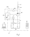
- Figure 9 shows a second embodiment of a pumping system SP2 for distributing fluids in a plant object of the present invention.
- volumetric pump 101a combined with a pneumatic accumulator 150 is used.
- volumetric pump 101a is operated by an electrical motor 102 and a maximum pressure valve 103 is also envisaged.
- the system is completed by a one-way valve 110 which avoids the flow-back from accumulator 150 towards pump 101a, and a solenoid valve 111 (3-ways/2-positions) which in the event of an emergency, a blackout or simply when electrical panel EQ is switched off and the workshop is closed, secures hydraulic circuit C1 by isolating pumping assembly 100 and relieving hydraulic circuit C1 though a one-way valve 112.
- electrical panel EQ controls solenoid valve 111 and manages electrical motor 102 through ON/OFF enabling generated by a pressure switch 113 with two intervention thresholds P max -P min (or, alternatively, two pressure switches, one of which calibrated to P max and the other to P min ). In this way, pump 101a only starts up when the pressure in hydraulic circuit C1 drops under threshold P min and is switched off when P max is reached.
- P min will be equal to the pressure required by hydraulic circuit C1 to ensure good dispensing also in adverse operating conditions.
- Pneumatic accumulator 150 (see figure 11, 12) chosen for the application comprises a metallic container CM, containing a closed bag (MB) or membrane.
- Bag MB separate one chamber of the liquid CLL from the space occupied by the gas CG.
- bag MB filled with nitrogen at a pressure P N , occupies the entire volume of metallic container CM. Therefore, by connecting pneumatic accumulator 150 to pressurised hydraulic circuit C1, if the pressure P of the fluid is P ⁇ P N the fluid cannot enter into liquid chamber CLL.
- bag MB is further compressed, determining a better capacity of pneumatic accumulator 150.
- pneumatic accumulator 150 represents a considerable reserve of pressurised fluid, it must be isolated by means of solenoid valve 111 in order to secure the plant.
- solenoid valve 111 When solenoid valve 111 is not powered, it is positioned so that the delivery of pumping unit 100 is closed and hydraulic circuit C1 is relieved.
- One-way valve 112 on relief is calibrated to 0.5 bars to avoid the pipes from being entirely emptied and the formation of air bubbles.
- solenoid valve 11 is powered and hydraulic circuit C1 is pressurised again.
- the operation of the system envisages a first filling step of pneumatic accumulator 150, which is filled with fluid, compressing the nitrogen present in bag MB and making the pressure in the hydraulic circuit C1 rise.
- the pressure switch 113 switches and shuts down electrical motor (102).
- fluid FL1 is provided by pneumatic accumulator 150 without requiring a new start-up of pump 101a.
- the pressure in hydraulic circuit C1 drops to P min causing a new intervention of pressure switch 113 and the start-up of electrical motor 102.
- Pump 101a will continue to run regardless of the active dispensing requests, until hydraulic accumulator 150 is fully recharged and the pressure has returned to P max .
- pneumatic accumulator 150 works between P max and P min , consequently, if P min is approximately equal to P N , the final efficiency will be maximum; otherwise, a higher P min will correspond to a lower actually exploited accumulation capacity. Indeed, in this case, the accumulated fluid volume in the operating range between P N and P min cannot be recovered.
- Figure 10 shows a third embodiment of a pumping system SP3 used in a distributing plant object of the present invention.
- This third embodiment aims at increasing the efficiency of pumping system SP2 (described with reference to figure 9).
- variable flow rate pumping assembly 100 is similar to that described in the second embodiment (figure 9) with the sole exception of the part related to the presence of transducers 200, which define the operating parameters of the system.
- pressure switch 113 with two intervention thresholds P max -P min seen in relation to figure 9, is replaced by an electronic board 201 (figure 10) which reads the pressure and temperature of the fluid in hydraulic circuit C1 and processes the run/stop enable for electrical panel EQ, which, as usual, controls electrical motor 102.
- the fluid pressure is read by a pressure transducer 202, while the temperature is read by a temperature transducer 203.
- Electronic board 201 is programmed to provide an OFF signal when the pressure of fluid FL1 in hydraulic circuit C1 reaches the maximum reference pressure P max , defined according to the working pressure P e of the weakest component, and to provide an ON signal when the pressure drops under threshold P min , calculated according to the temperature of fluid FL1.
- electronic board 201 In order to define P min , electronic board 201 must be set so as to define the type of fluid FL1 treated and with at least two significant value pairs (pressure, temperature) to define the features of pumping system SP3.
- the minimum pressure P min is instead calculated on a case-by-case basis according to a characterised operating curve of the system.
- Such curve is configured by means of the initial settings of electronic board 201 which relate to the type of fluid FL1 (according to the SAE classification of viscosity and temperature) and at least one reference point for pressure and temperature.
- the type of fluid LF1 is selected, electronic board 201 detects the temperature and the operator performs tests to define the minimum optimal pressure P min for plant operation.
- electronic board 201 is able to process a numeric model for redefining, as temperature varies, pressure P min adapted to ensure the required performance in terms of flow rate and number of ensured contemporary loads.
Landscapes
- Engineering & Computer Science (AREA)
- Mechanical Engineering (AREA)
- Physics & Mathematics (AREA)
- General Physics & Mathematics (AREA)
- Automation & Control Theory (AREA)
- Mathematical Physics (AREA)
- Theoretical Computer Science (AREA)
- Loading And Unloading Of Fuel Tanks Or Ships (AREA)
- Flow Control (AREA)
- Fluid-Pressure Circuits (AREA)
- Nozzles (AREA)
- Medicines Containing Plant Substances (AREA)
Priority Applications (5)
| Application Number | Priority Date | Filing Date | Title |
|---|---|---|---|
| EP06425492A EP1880975A1 (fr) | 2006-07-17 | 2006-07-17 | Installation de distribution de fluide pour un atelier |
| PCT/IB2007/002015 WO2008010068A2 (fr) | 2006-07-17 | 2007-07-17 | Système de régulation de débit pour une installation de distribution de fluide d'atelier |
| EP07866555A EP2043947B1 (fr) | 2006-07-17 | 2007-07-17 | Tête de pistolage de fluide utilisée dans une installation de distribution de fluide d'atelier |
| PCT/EP2007/057397 WO2008009692A1 (fr) | 2006-07-17 | 2007-07-17 | Installation de distribution de fluides dans un atelier |
| PCT/IB2007/002018 WO2008053286A2 (fr) | 2006-07-17 | 2007-07-17 | Tête de pistolage de fluide utilisée dans une installation de distribution de fluide d'atelier |
Applications Claiming Priority (1)
| Application Number | Priority Date | Filing Date | Title |
|---|---|---|---|
| EP06425492A EP1880975A1 (fr) | 2006-07-17 | 2006-07-17 | Installation de distribution de fluide pour un atelier |
Publications (2)
| Publication Number | Publication Date |
|---|---|
| EP1880975A1 true EP1880975A1 (fr) | 2008-01-23 |
| EP1880975A8 EP1880975A8 (fr) | 2008-08-20 |
Family
ID=37478832
Family Applications (2)
| Application Number | Title | Priority Date | Filing Date |
|---|---|---|---|
| EP06425492A Withdrawn EP1880975A1 (fr) | 2006-07-17 | 2006-07-17 | Installation de distribution de fluide pour un atelier |
| EP07866555A Not-in-force EP2043947B1 (fr) | 2006-07-17 | 2007-07-17 | Tête de pistolage de fluide utilisée dans une installation de distribution de fluide d'atelier |
Family Applications After (1)
| Application Number | Title | Priority Date | Filing Date |
|---|---|---|---|
| EP07866555A Not-in-force EP2043947B1 (fr) | 2006-07-17 | 2007-07-17 | Tête de pistolage de fluide utilisée dans une installation de distribution de fluide d'atelier |
Country Status (2)
| Country | Link |
|---|---|
| EP (2) | EP1880975A1 (fr) |
| WO (3) | WO2008010068A2 (fr) |
Cited By (2)
| Publication number | Priority date | Publication date | Assignee | Title |
|---|---|---|---|---|
| EP2154104A1 (fr) * | 2008-07-21 | 2010-02-17 | Filcar S.p.A. | Installation pour la distribution de fluide dans un atelier |
| EP3369700A1 (fr) * | 2017-03-03 | 2018-09-05 | Elaflex Hiby Tanktechnik GmbH & Co. | Buse de distribution pour deux debits maximales |
Citations (5)
| Publication number | Priority date | Publication date | Assignee | Title |
|---|---|---|---|---|
| GB201729A (en) * | 1922-07-05 | 1923-08-09 | William Ernest Wyatt Millingto | Improvements in or relating to hydraulic supply systems |
| EP0098709A1 (fr) * | 1982-07-01 | 1984-01-18 | Castrol Limited | Système pour délivrer du liquide |
| EP0781725A1 (fr) * | 1995-12-29 | 1997-07-02 | Graco Inc. | Système de distribution de fluides multiples |
| US5934508A (en) * | 1995-07-11 | 1999-08-10 | Fe Petro Inc. | Variable speed pump-motor assembly for fuel dispensing system |
| EP1072556A1 (fr) * | 1999-07-22 | 2001-01-31 | Bürkert Werke GmbH & Co. | Système de soutirage pour pompe à essence |
Family Cites Families (4)
| Publication number | Priority date | Publication date | Assignee | Title |
|---|---|---|---|---|
| US2198487A (en) * | 1936-12-22 | 1940-04-23 | Martin A Sisk | Automatic valve |
| US3204659A (en) * | 1962-08-29 | 1965-09-07 | Liquid Controls Corp | Liquid flow control device |
| JPS485293Y1 (fr) * | 1966-08-06 | 1973-02-10 | ||
| US7156120B2 (en) * | 2004-07-28 | 2007-01-02 | Cct Manufacturing, Inc. | Inline liquid flow control valve |
-
2006
- 2006-07-17 EP EP06425492A patent/EP1880975A1/fr not_active Withdrawn
-
2007
- 2007-07-17 WO PCT/IB2007/002015 patent/WO2008010068A2/fr not_active Ceased
- 2007-07-17 WO PCT/IB2007/002018 patent/WO2008053286A2/fr not_active Ceased
- 2007-07-17 EP EP07866555A patent/EP2043947B1/fr not_active Not-in-force
- 2007-07-17 WO PCT/EP2007/057397 patent/WO2008009692A1/fr not_active Ceased
Patent Citations (5)
| Publication number | Priority date | Publication date | Assignee | Title |
|---|---|---|---|---|
| GB201729A (en) * | 1922-07-05 | 1923-08-09 | William Ernest Wyatt Millingto | Improvements in or relating to hydraulic supply systems |
| EP0098709A1 (fr) * | 1982-07-01 | 1984-01-18 | Castrol Limited | Système pour délivrer du liquide |
| US5934508A (en) * | 1995-07-11 | 1999-08-10 | Fe Petro Inc. | Variable speed pump-motor assembly for fuel dispensing system |
| EP0781725A1 (fr) * | 1995-12-29 | 1997-07-02 | Graco Inc. | Système de distribution de fluides multiples |
| EP1072556A1 (fr) * | 1999-07-22 | 2001-01-31 | Bürkert Werke GmbH & Co. | Système de soutirage pour pompe à essence |
Cited By (3)
| Publication number | Priority date | Publication date | Assignee | Title |
|---|---|---|---|---|
| EP2154104A1 (fr) * | 2008-07-21 | 2010-02-17 | Filcar S.p.A. | Installation pour la distribution de fluide dans un atelier |
| EP3369700A1 (fr) * | 2017-03-03 | 2018-09-05 | Elaflex Hiby Tanktechnik GmbH & Co. | Buse de distribution pour deux debits maximales |
| US10988370B2 (en) | 2017-03-03 | 2021-04-27 | Elaflex Hiby Gmbh & Co. Kg | Signal-controlled flow fuel delivery valve |
Also Published As
| Publication number | Publication date |
|---|---|
| WO2008009692A1 (fr) | 2008-01-24 |
| WO2008053286A3 (fr) | 2008-06-26 |
| EP2043947B1 (fr) | 2012-10-31 |
| EP1880975A8 (fr) | 2008-08-20 |
| WO2008010068A2 (fr) | 2008-01-24 |
| WO2008053286A2 (fr) | 2008-05-08 |
| EP2043947A2 (fr) | 2009-04-08 |
| WO2008010068A8 (fr) | 2008-06-19 |
| WO2008010068A3 (fr) | 2008-08-07 |
Similar Documents
| Publication | Publication Date | Title |
|---|---|---|
| US5538051A (en) | CNG refueling system for multiple vehicles | |
| US20050047930A1 (en) | System for controlling a hydraulic variable-displacement pump | |
| US4383412A (en) | Multiple pump load sensing system | |
| US4502845A (en) | Multistage gear pump and control valve arrangement | |
| EP0114650A1 (fr) | Circuit hydraulique à charge variable | |
| US6997685B2 (en) | Hydraulic system comprising a main pump and a precompression pump | |
| WO2007103043A2 (fr) | Systeme de distribution de liquide | |
| CN102588578A (zh) | 具有流量增大的变速器液压控制系统 | |
| US6109030A (en) | Apparatus and method for ganging multiple open circuit pumps | |
| US20110079654A1 (en) | Irrigation evacuation system | |
| WO2008009692A1 (fr) | Installation de distribution de fluides dans un atelier | |
| US5133644A (en) | Multi-pressure compensation of variable displacement pump | |
| US4777797A (en) | Hydraulic system with suction maintenance of its control pump | |
| US3572381A (en) | Pump pressure system | |
| JP5553614B2 (ja) | 液圧システム | |
| US7017470B2 (en) | Flow control apparatus for construction heavy equipment | |
| CN218991995U (zh) | 液压控制系统及作业机械 | |
| US20140086759A1 (en) | Hydraulic Power System for HVAC Compressor | |
| CN115657747B (zh) | 基于电动泵转速值控制离合器压力值的方法和装置 | |
| KR101740925B1 (ko) | 가변 변위 펌프 및 릴리프 밸브를 포함하는 유압 어셈블리 | |
| CN220186492U (zh) | 润滑系统与挖掘机 | |
| US20160252179A1 (en) | Hydraulic system for transmission assembly | |
| SU1161020A1 (ru) | Оросительна система | |
| NO311640B1 (no) | Blandingsapparat for utspröyting av en v¶skeblanding | |
| JP3172499B2 (ja) | 組み合わせポンプ装置 |
Legal Events
| Date | Code | Title | Description |
|---|---|---|---|
| PUAI | Public reference made under article 153(3) epc to a published international application that has entered the european phase |
Free format text: ORIGINAL CODE: 0009012 |
|
| AK | Designated contracting states |
Kind code of ref document: A1 Designated state(s): AT BE BG CH CY CZ DE DK EE ES FI FR GB GR HU IE IS IT LI LT LU LV MC NL PL PT RO SE SI SK TR |
|
| AX | Request for extension of the european patent |
Extension state: AL BA HR MK YU |
|
| 17P | Request for examination filed |
Effective date: 20080723 |
|
| AKX | Designation fees paid |
Designated state(s): AT BE BG CH CY CZ DE DK EE ES FI FR GB GR HU IE IS IT LI LT LU LV MC NL PL PT RO SE SI SK TR |
|
| 17Q | First examination report despatched |
Effective date: 20081008 |
|
| STAA | Information on the status of an ep patent application or granted ep patent |
Free format text: STATUS: THE APPLICATION IS DEEMED TO BE WITHDRAWN |
|
| 18D | Application deemed to be withdrawn |
Effective date: 20090421 |