EP1881181A2 - Belüftung eines Hohlraums hinter dem Rad eines Radialverdichters in einer Strömungsmaschine - Google Patents
Belüftung eines Hohlraums hinter dem Rad eines Radialverdichters in einer Strömungsmaschine Download PDFInfo
- Publication number
- EP1881181A2 EP1881181A2 EP07290843A EP07290843A EP1881181A2 EP 1881181 A2 EP1881181 A2 EP 1881181A2 EP 07290843 A EP07290843 A EP 07290843A EP 07290843 A EP07290843 A EP 07290843A EP 1881181 A2 EP1881181 A2 EP 1881181A2
- Authority
- EP
- European Patent Office
- Prior art keywords
- downstream
- deflector
- diffuser
- impeller
- annular
- Prior art date
- Legal status (The legal status is an assumption and is not a legal conclusion. Google has not performed a legal analysis and makes no representation as to the accuracy of the status listed.)
- Granted
Links
Images


Classifications
-
- F—MECHANICAL ENGINEERING; LIGHTING; HEATING; WEAPONS; BLASTING
- F02—COMBUSTION ENGINES; HOT-GAS OR COMBUSTION-PRODUCT ENGINE PLANTS
- F02C—GAS-TURBINE PLANTS; AIR INTAKES FOR JET-PROPULSION PLANTS; CONTROLLING FUEL SUPPLY IN AIR-BREATHING JET-PROPULSION PLANTS
- F02C7/00—Features, components parts, details or accessories, not provided for in, or of interest apart form groups F02C1/00 - F02C6/00; Air intakes for jet-propulsion plants
- F02C7/12—Cooling of plants
- F02C7/16—Cooling of plants characterised by cooling medium
- F02C7/18—Cooling of plants characterised by cooling medium the medium being gaseous, e.g. air
-
- F—MECHANICAL ENGINEERING; LIGHTING; HEATING; WEAPONS; BLASTING
- F01—MACHINES OR ENGINES IN GENERAL; ENGINE PLANTS IN GENERAL; STEAM ENGINES
- F01D—NON-POSITIVE DISPLACEMENT MACHINES OR ENGINES, e.g. STEAM TURBINES
- F01D5/00—Blades; Blade-carrying members; Heating, heat-insulating, cooling or antivibration means on the blades or the members
- F01D5/02—Blade-carrying members, e.g. rotors
- F01D5/04—Blade-carrying members, e.g. rotors for radial-flow machines or engines
- F01D5/043—Blade-carrying members, e.g. rotors for radial-flow machines or engines of the axial inlet- radial outlet, or vice versa, type
- F01D5/046—Heating, heat insulation or cooling means
-
- F—MECHANICAL ENGINEERING; LIGHTING; HEATING; WEAPONS; BLASTING
- F02—COMBUSTION ENGINES; HOT-GAS OR COMBUSTION-PRODUCT ENGINE PLANTS
- F02C—GAS-TURBINE PLANTS; AIR INTAKES FOR JET-PROPULSION PLANTS; CONTROLLING FUEL SUPPLY IN AIR-BREATHING JET-PROPULSION PLANTS
- F02C3/00—Gas-turbine plants characterised by the use of combustion products as the working fluid
- F02C3/04—Gas-turbine plants characterised by the use of combustion products as the working fluid having a turbine driving a compressor
- F02C3/08—Gas-turbine plants characterised by the use of combustion products as the working fluid having a turbine driving a compressor the compressor comprising at least one radial stage
-
- F—MECHANICAL ENGINEERING; LIGHTING; HEATING; WEAPONS; BLASTING
- F04—POSITIVE - DISPLACEMENT MACHINES FOR LIQUIDS; PUMPS FOR LIQUIDS OR ELASTIC FLUIDS
- F04D—NON-POSITIVE-DISPLACEMENT PUMPS
- F04D29/00—Details, component parts, or accessories
- F04D29/26—Rotors specially for elastic fluids
- F04D29/28—Rotors specially for elastic fluids for centrifugal or helico-centrifugal pumps for radial-flow or helico-centrifugal pumps
- F04D29/284—Rotors specially for elastic fluids for centrifugal or helico-centrifugal pumps for radial-flow or helico-centrifugal pumps for compressors
-
- F—MECHANICAL ENGINEERING; LIGHTING; HEATING; WEAPONS; BLASTING
- F04—POSITIVE - DISPLACEMENT MACHINES FOR LIQUIDS; PUMPS FOR LIQUIDS OR ELASTIC FLUIDS
- F04D—NON-POSITIVE-DISPLACEMENT PUMPS
- F04D29/00—Details, component parts, or accessories
- F04D29/58—Cooling; Heating; Diminishing heat transfer
- F04D29/582—Cooling; Heating; Diminishing heat transfer specially adapted for elastic fluid pumps
- F04D29/584—Cooling; Heating; Diminishing heat transfer specially adapted for elastic fluid pumps cooling or heating the machine
-
- F—MECHANICAL ENGINEERING; LIGHTING; HEATING; WEAPONS; BLASTING
- F05—INDEXING SCHEMES RELATING TO ENGINES OR PUMPS IN VARIOUS SUBCLASSES OF CLASSES F01-F04
- F05D—INDEXING SCHEME FOR ASPECTS RELATING TO NON-POSITIVE-DISPLACEMENT MACHINES OR ENGINES, GAS-TURBINES OR JET-PROPULSION PLANTS
- F05D2260/00—Function
- F05D2260/20—Heat transfer, e.g. cooling
- F05D2260/221—Improvement of heat transfer
-
- Y—GENERAL TAGGING OF NEW TECHNOLOGICAL DEVELOPMENTS; GENERAL TAGGING OF CROSS-SECTIONAL TECHNOLOGIES SPANNING OVER SEVERAL SECTIONS OF THE IPC; TECHNICAL SUBJECTS COVERED BY FORMER USPC CROSS-REFERENCE ART COLLECTIONS [XRACs] AND DIGESTS
- Y02—TECHNOLOGIES OR APPLICATIONS FOR MITIGATION OR ADAPTATION AGAINST CLIMATE CHANGE
- Y02T—CLIMATE CHANGE MITIGATION TECHNOLOGIES RELATED TO TRANSPORTATION
- Y02T50/00—Aeronautics or air transport
- Y02T50/60—Efficient propulsion technologies, e.g. for aircraft
Definitions
- the present invention relates to the ventilation of a downstream cavity of a centrifugal compressor wheel in a turbomachine, such as in particular an airplane turbojet or turboprop.
- the annular cavity which is formed downstream of the impeller of a centrifugal compressor in a turbomachine must be ventilated to evacuate the thermal energy provided by the impeller. This ventilation is usually done by air intake at the outlet of the compressor, at the junction with the inlet of an annular diffuser which feeds a combustion chamber.
- This diffuser comprises a downstream annular flange with axial section substantially L whose substantially radial upstream portion extends, with a small axial clearance, along the downstream face of the impeller, and whose downstream portion is substantially cylindrical.
- the air taken at the outlet of the compressor flows from the outside to the inside in the radial annular space formed between the impeller and the radial portion of the diffuser flange and then passes into the downstream cavity of the impeller.
- the air in the cavity is subjected to large centrifugal forces and is driven by the rotation of the impeller which causes a recirculation zone of air in the cavity and a rise of a part of this air along the downstream side of the impeller, from the inside to the outside.
- This air heats by viscous friction on the downstream face of the impeller and mixes with the air taken out of the compressor, increasing the temperature of this air.
- this air reheats the downstream side of the impeller, which can reach and exceed a maximum allowable value, which results in a creep material.
- the invention aims in particular to provide a simple, effective and economical solution to this problem of the prior art.
- a turbomachine comprising a centrifugal compressor and an annular diffuser arranged at the outlet of the compressor, the diffuser comprising a downstream annular flange with substantially L-shaped section which extends downstream of the impeller of the compressor and which delimits with a face radially downstream of the impeller an annular cavity ventilated by sampling air at the outlet of the compressor, the collected air flowing in the cavity downstream and towards the axis of rotation of the compressor, characterized in that at least one annular deflector is mounted in this cavity and extends between the downstream face of the impeller and the downstream annular flange of the diffuser to oppose the rise of hot air along the downstream face of the impeller and to accelerate the air taken out compressor and drive the hot air downstream.
- the annular deflector according to the invention prevents the rise of hot air along the downstream face of the impeller and forms a reduction of the passage section of the air taken at the outlet of the compressor, to accelerate this air and cause shearing of the air. the warmer air that went up along the radial face of the impeller and which was deflected by the deflector, and a drive of this hotter air along the cylindrical portion of the annular flange of the diffuser.
- the deflector is located radially at the junction between a radial portion and a cylindrical portion of the downstream annular flange of the diffuser.
- the deflector is most effective, in terms of the deviation of the warmer air that has risen up the downstream side of the impeller, shearing and driving that warmer air through the air taken out of the compressor.
- the deflector is formed projecting on the downstream face of the impeller and has a substantially cylindrical shape.
- this deflector extends axially to near the downstream annular flange of the diffuser, and has an axial dimension greater than or equal to the thickness of the hot air layer rising along the wheel.
- This hot air is deflected downstream by the impeller of the wheel and is driven by the air taken from the output of the compressor and which passes between the baffle and the flange of the diffuser.
- the baffle is formed protruding from the annular flange of the diffuser and extends axially upstream to the vicinity of the impeller.
- This deflector is preferably formed at the junction between the radial portion and the cylindrical portion of the diffuser flange.
- a first deflector is formed projecting on the downstream side of the wheel and a second deflector is formed protruding on the downstream annular flange of the diffuser, these deflectors extending towards one another and delimiting between them an annular outlet passage of the air taken at the outlet of the compressor.
- the baffle formed on the impeller is located radially inside the baffle formed on the annular flange of the diffuser.
- the deflector is formed protruding on an annular shield of thermal protection covering the downstream face of the impeller and rotating with the impeller, the deflector extending downstream to near the flange of the diffuser.
- This deflector is preferably located at the junction between the radial and cylindrical portions of the flange of the diffuser.
- the deflector may have a square, rectangular or triangular shape in axial section.
- FIG. 1 represents a portion of a turbomachine, such as a turbojet engine or an airplane turboprop, comprising, from upstream to downstream, in the direction of the flow of gases inside the turbomachine, a centrifugal stage compressor 10, a diffuser 12 and a combustion chamber 14.
- a turbomachine such as a turbojet engine or an airplane turboprop
- the inlet of the compressor stage 10 is oriented upstream, substantially parallel to the axis 16 of the turbomachine, and its outlet 18 is oriented radially outwards, substantially perpendicular to the axis 16 of the turbomachine .
- the diffuser 12 has an annular shape bent at 90 ° and comprises an inlet 20 aligned with the outlet 18 of the compressor, and an outlet 22 which faces downstream and opens out radially outside the combustion chamber 14.
- the diffuser 12 is carried by an outer casing 24 which externally surrounds the compressor 10, the diffuser 12 and the combustion chamber 14.
- the diffuser 12 comprises a downstream annular flange 26 of substantially L-shaped section which comprises a substantially radial upstream portion 28 which extends inwardly from the inlet 20 of the diffuser 12, and a substantially cylindrical downstream portion 30 which ends at its downstream end by an annular flange 32 fixed by appropriate means of the screw-nut type on means 34 of ventilation air injection and / or cooling of components (in particular of turbine) located downstream of the combustion chamber 14.
- junction 29 between the radial and cylindrical portions 28 of the flange has a rounded shape in axial section and comprises a concave annular surface oriented downstream and outward and a convex annular surface facing upstream and towards the inside.
- the radial portion 28 of the flange 26 extends, with low axial clearance, downstream and along the impeller 36 of the compressor, this axial clearance increasing slightly in the direction of the axis 16 of rotation of the impeller and being at the maximum level. the aforementioned junction 29 of the flange.
- the flange 26 delimits with a downstream radial face 70 of the wheel 36 an annular cavity 40 which communicates with the compressor outlet by the radial annular space 38 formed between the wheel 36 and the radial portion 28 of the flange.
- the combustion chamber 14 comprises two coaxial walls of revolution 42, 44 extending one inside the other and connected at their upstream ends to a wall 46 of the chamber bottom, these walls 42, 44 and 46 delimiting between them an annular enclosure in which fuel is supplied by injectors.
- the radially outer wall 44 of the chamber is fixed at its downstream end to the outer casing 24, and its radially inner wall 42 is connected at its downstream end to a frustoconical shell 50 which has at its radially inner end an internal annular flange 52 for fixing. on the aforementioned injection means 34.
- injection means 42 comprise a straight-angled annular duct whose inlet 54 opens radially outwards and is located downstream of the flange 32 of the flange and upstream of the flange 52 of the shell 50, and the outlet 56 is oriented downstream and is located radially inside the shell 50.
- a small part of the air flow leaving the centrifugal compressor 10 passes into the radial space 38 formed between the impeller 36 of the compressor and the radial portion 28 of the flange 26 of the diffuser to ventilate the downstream cavity 40 of the impeller and avoid an accumulation of heat produced by viscous friction of the air driven by the rotation of the wheel.
- the ventilation air is discharged (arrow 74) downstream through orifices provided on the flanges 32 and 52 of the flange 26 and the collar 50 and aligned with corresponding orifices provided on the injection means 34.
- an air recirculation zone 72 is created in the cavity 40 under the effect of centrifugal forces and rotation of the impeller. Part of this air rises (arrow 76) along the wheel 36, from the inside to the outside and heats by viscous friction on the downstream face 70 of the wheel.
- This hot air 76 mixes with the air 68 taken at the outlet of the compressor and increases its temperature, this convective air mixture being able to raise the temperature of the downstream side of the impeller, which represents a risk of deterioration of the impeller.
- the invention provides a solution to this problem with at least one annular baffle which extends around the axis 16 of rotation of the impeller, between the flange 26 of the diffuser and the downstream face 70 of the impeller, and which allows to deviate downstream the warm air rising along this face.
- the deflector 80 is formed protruding on the downstream face 70 of the impeller 36 and is located radially at the junction 29 between the radial and cylindrical portions 28 of the flange 26.
- the deflector 80 has a shape for example square in axial section and extends axially to a small distance from the junction 29 of the flange 26, defining therewith an annular passage of air outlet of the radial space 38.
- the air leaving the radial space 38 through this passage is accelerated and flows around the axis of rotation of the compressor and upstream downstream along the cylindrical portion 30 of the flange (arrows 86). It drives downstream the warmer air which has risen along the radial face 70 of the impeller and which has been deflected downstream by the deflector 80, then is evacuated through the aforementioned orifices of the flanges 32, 52 and injection means 34 (arrow 89).
- the deflector 80 may be formed integrally with the wheel 36, as shown, or be reported and fixed on the downstream face 70 of the wheel.
- the axial dimension of the deflector 80 is equal to or greater than the thickness of the hot air layer upstream of the downstream face 70 of the impeller in order to deflect all of this air layer downstream.
- the axial dimension of the deflector 80 is about 1 cm.
- the baffle 90 is formed protruding from the flange 26 of the diffuser, at the junction 29 of the flange, and extends axially upstream to the vicinity of the impeller 36.
- the deflector 90 has an approximately square shape in axial section and ends at a low axial distance from the downstream face 70 of the impeller, defining therewith an annular air outlet passage of the radial space 38.
- the deflector 90 may be formed integrally with the flange 26 of the diffuser or be attached to the flange.
- the deflector 100 is carried by an annular thermal protection shield 102 which is integral with rotation of the wheel 36, and which covers the downstream face 70 of the wheel, the radially outer end of the shield being located approximately at the junction 29 of the flange.
- the shield 102 prevents the warmer air circulating in the downstream cavity 40 from coming into contact with the downstream face of the impeller.
- the deflector 100 is formed projecting near the radially outer end of the shield 102 and extends axially downstream inside the junction 29 of the flange 26 and at a short radial distance therefrom.
- This deflector 100 has a shape, for example rectangular in axial section and ends at a small distance from the junction 29 of the flange 26, defining therewith an annular air outlet passage of the radial space 38.
- the deflector 100 can be attached and fixed on the shield 102 or formed in one piece with the shield.
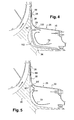
- two deflectors 80 ', 90' are carried respectively by the impeller 36 and the flange 26 of the diffuser, and define therebetween an annular air outlet passage of the radial space 38, which corresponds to a combination of the embodiments of FIGS. 2 and 3.
- the deflector 80 'carried by the wheel 36 has a triangular shape in axial section whose apex is oriented towards the flange 26.
- the deflector 90 'of the flange is substantially identical to the deflector 90 of Figure 3 and extends axially around the deflector 80'. The operations of the embodiments of FIGS. 2 and 3 are combined.
Landscapes
- Engineering & Computer Science (AREA)
- Mechanical Engineering (AREA)
- General Engineering & Computer Science (AREA)
- Chemical & Material Sciences (AREA)
- Combustion & Propulsion (AREA)
- Physics & Mathematics (AREA)
- Thermal Sciences (AREA)
- Structures Of Non-Positive Displacement Pumps (AREA)
Applications Claiming Priority (1)
| Application Number | Priority Date | Filing Date | Title |
|---|---|---|---|
| FR0606543A FR2904037B1 (fr) | 2006-07-19 | 2006-07-19 | Ventilation d'une cavite aval de rouet de compresseur centrifuge |
Publications (3)
| Publication Number | Publication Date |
|---|---|
| EP1881181A2 true EP1881181A2 (de) | 2008-01-23 |
| EP1881181A3 EP1881181A3 (de) | 2008-04-09 |
| EP1881181B1 EP1881181B1 (de) | 2017-12-13 |
Family
ID=37692473
Family Applications (1)
| Application Number | Title | Priority Date | Filing Date |
|---|---|---|---|
| EP07290843.7A Active EP1881181B1 (de) | 2006-07-19 | 2007-07-04 | Strömungsmaschine |
Country Status (6)
| Country | Link |
|---|---|
| US (1) | US8226353B2 (de) |
| EP (1) | EP1881181B1 (de) |
| JP (1) | JP5087808B2 (de) |
| CA (1) | CA2594139C (de) |
| FR (1) | FR2904037B1 (de) |
| RU (1) | RU2447292C2 (de) |
Cited By (5)
| Publication number | Priority date | Publication date | Assignee | Title |
|---|---|---|---|---|
| FR2960923A1 (fr) * | 2010-06-08 | 2011-12-09 | Snecma | Controle de la poussee axiale par guidage de l'air preleve sur un compresseur centrifuge |
| FR3070058A1 (fr) * | 2017-08-14 | 2019-02-15 | Safran Aircraft Engines | Turbomachine pour aeronef comprenant un element de refroidissement ameliorant le refroidissement par convection et offrant un refroidissement par impact de jet d'air d'une bride de liaison terminale de paroi de chambre annulaire de combustion |
| EP3708804A1 (de) * | 2019-03-15 | 2020-09-16 | Pratt & Whitney Canada Corp. | Laufradspitzenhohlraum |
| US11268536B1 (en) | 2020-09-08 | 2022-03-08 | Pratt & Whitney Canada Corp. | Impeller exducer cavity with flow recirculation |
| EP4293200A3 (de) * | 2022-03-28 | 2024-02-21 | Pratt & Whitney Canada Corp. | Flugzeugtriebwerk mit radialem abstand zwischen dichtung und deflektor |
Families Citing this family (12)
| Publication number | Priority date | Publication date | Assignee | Title |
|---|---|---|---|---|
| WO2012051442A2 (en) * | 2010-10-13 | 2012-04-19 | The Government Of The United States Of America, As Represented By The Secretary Of The Navy | Thermally insulating turbine coupling |
| US9228497B2 (en) * | 2010-12-30 | 2016-01-05 | Rolls-Royce Corporation | Gas turbine engine with secondary air flow circuit |
| DE102013207220B3 (de) * | 2013-04-22 | 2014-09-18 | Siemens Aktiengesellschaft | Turbomaschine |
| GB2513664B (en) * | 2013-05-03 | 2016-01-06 | Dyson Technology Ltd | Compressor |
| US10968917B2 (en) * | 2014-10-27 | 2021-04-06 | Zhongshan Broad-Ocean Motor Manufacturing Co., Ltd. | Blower comprising a pressure measuring connector |
| RU2602029C1 (ru) * | 2015-09-21 | 2016-11-10 | Акционерное общество "Климов"(АО"Климов") | Газогенератор газотурбинного двигателя |
| US10830144B2 (en) * | 2016-09-08 | 2020-11-10 | Rolls-Royce North American Technologies Inc. | Gas turbine engine compressor impeller cooling air sinks |
| JP2020165415A (ja) * | 2019-03-29 | 2020-10-08 | 三菱重工業株式会社 | 回転機械 |
| DE102019123002A1 (de) * | 2019-08-27 | 2021-03-04 | Rolls-Royce Deutschland Ltd & Co Kg | Gasturbinentriebwerk eines Luftfahrzeuges |
| US11525393B2 (en) | 2020-03-19 | 2022-12-13 | Rolls-Royce Corporation | Turbine engine with centrifugal compressor having impeller backplate offtake |
| US11773773B1 (en) | 2022-07-26 | 2023-10-03 | Rolls-Royce North American Technologies Inc. | Gas turbine engine centrifugal compressor with impeller load and cooling control |
| CN118499280B (zh) * | 2024-07-22 | 2024-11-15 | 南京通莱环保科技有限公司 | 一种工业用高效过滤循环水泵 |
Citations (4)
| Publication number | Priority date | Publication date | Assignee | Title |
|---|---|---|---|---|
| US3199294A (en) | 1961-04-25 | 1965-08-10 | Bmw Triebwerkbau Gmbh | Air-cooled support and guide vane assembly for a gas turbine engine |
| US4277222A (en) | 1979-01-11 | 1981-07-07 | Teledyne Industries, Inc. | Turbine engine compressor |
| US5996331A (en) | 1997-09-15 | 1999-12-07 | Alliedsignal Inc. | Passive turbine coolant regulator responsive to engine load |
| US6257834B1 (en) | 1998-02-10 | 2001-07-10 | Asea Brown Boveri Ag | Method and arrangement for the indirect cooling of the flow in radial gaps formed between rotors and stators of turbomachines |
Family Cites Families (10)
| Publication number | Priority date | Publication date | Assignee | Title |
|---|---|---|---|---|
| US2855143A (en) * | 1954-02-16 | 1958-10-07 | Sulzer Ag | Multistage radial flow turbomachine |
| US4248566A (en) * | 1978-10-06 | 1981-02-03 | General Motors Corporation | Dual function compressor bleed |
| JPS58173701U (ja) * | 1982-05-17 | 1983-11-19 | ヤンマーディーゼル株式会社 | ガスタ−ビン |
| US5601406A (en) * | 1994-12-21 | 1997-02-11 | Alliedsignal Inc. | Centrifugal compressor hub containment assembly |
| RU2130124C1 (ru) * | 1996-05-28 | 1999-05-10 | Акционерное общество "Авиадвигатель" | Ротор многоступенчатой турбины |
| US6000906A (en) * | 1997-09-12 | 1999-12-14 | Alliedsignal Inc. | Ceramic airfoil |
| JP2002031085A (ja) * | 2000-07-18 | 2002-01-31 | Yanmar Diesel Engine Co Ltd | ガスタービンの圧縮機のバランス機構 |
| JP4091874B2 (ja) * | 2003-05-21 | 2008-05-28 | 本田技研工業株式会社 | ガスタービンエンジンの二次エア供給装置 |
| KR20040104772A (ko) * | 2003-06-03 | 2004-12-13 | 삼성전자주식회사 | 터보팬 및 이를 갖춘 공기조화기 |
| US7363762B2 (en) * | 2005-11-16 | 2008-04-29 | General Electric Company | Gas turbine engines seal assembly and methods of assembling the same |
-
2006
- 2006-07-19 FR FR0606543A patent/FR2904037B1/fr active Active
-
2007
- 2007-07-04 EP EP07290843.7A patent/EP1881181B1/de active Active
- 2007-07-16 CA CA2594139A patent/CA2594139C/fr active Active
- 2007-07-17 US US11/778,928 patent/US8226353B2/en active Active
- 2007-07-18 RU RU2007127562/06A patent/RU2447292C2/ru active
- 2007-07-18 JP JP2007186667A patent/JP5087808B2/ja active Active
Patent Citations (4)
| Publication number | Priority date | Publication date | Assignee | Title |
|---|---|---|---|---|
| US3199294A (en) | 1961-04-25 | 1965-08-10 | Bmw Triebwerkbau Gmbh | Air-cooled support and guide vane assembly for a gas turbine engine |
| US4277222A (en) | 1979-01-11 | 1981-07-07 | Teledyne Industries, Inc. | Turbine engine compressor |
| US5996331A (en) | 1997-09-15 | 1999-12-07 | Alliedsignal Inc. | Passive turbine coolant regulator responsive to engine load |
| US6257834B1 (en) | 1998-02-10 | 2001-07-10 | Asea Brown Boveri Ag | Method and arrangement for the indirect cooling of the flow in radial gaps formed between rotors and stators of turbomachines |
Cited By (7)
| Publication number | Priority date | Publication date | Assignee | Title |
|---|---|---|---|---|
| FR2960923A1 (fr) * | 2010-06-08 | 2011-12-09 | Snecma | Controle de la poussee axiale par guidage de l'air preleve sur un compresseur centrifuge |
| US8938975B2 (en) | 2010-06-08 | 2015-01-27 | Snecma | Control of axial thrust by guidance of the air drawn off from a centrifugal compressor |
| FR3070058A1 (fr) * | 2017-08-14 | 2019-02-15 | Safran Aircraft Engines | Turbomachine pour aeronef comprenant un element de refroidissement ameliorant le refroidissement par convection et offrant un refroidissement par impact de jet d'air d'une bride de liaison terminale de paroi de chambre annulaire de combustion |
| EP3708804A1 (de) * | 2019-03-15 | 2020-09-16 | Pratt & Whitney Canada Corp. | Laufradspitzenhohlraum |
| US11143201B2 (en) | 2019-03-15 | 2021-10-12 | Pratt & Whitney Canada Corp. | Impeller tip cavity |
| US11268536B1 (en) | 2020-09-08 | 2022-03-08 | Pratt & Whitney Canada Corp. | Impeller exducer cavity with flow recirculation |
| EP4293200A3 (de) * | 2022-03-28 | 2024-02-21 | Pratt & Whitney Canada Corp. | Flugzeugtriebwerk mit radialem abstand zwischen dichtung und deflektor |
Also Published As
| Publication number | Publication date |
|---|---|
| CA2594139C (fr) | 2014-09-16 |
| CA2594139A1 (fr) | 2008-01-19 |
| US20100028138A1 (en) | 2010-02-04 |
| FR2904037B1 (fr) | 2010-11-12 |
| JP2008025576A (ja) | 2008-02-07 |
| RU2007127562A (ru) | 2009-01-27 |
| JP5087808B2 (ja) | 2012-12-05 |
| US8226353B2 (en) | 2012-07-24 |
| EP1881181B1 (de) | 2017-12-13 |
| RU2447292C2 (ru) | 2012-04-10 |
| FR2904037A1 (fr) | 2008-01-25 |
| EP1881181A3 (de) | 2008-04-09 |
Similar Documents
| Publication | Publication Date | Title |
|---|---|---|
| EP1881181B1 (de) | Strömungsmaschine | |
| EP1882826B1 (de) | System zur Lüftung eines Hohlraums stromabwärts eines Zentrifugalverdichterrads | |
| EP1882815B1 (de) | Strömungsmaschine mit einem Kühlsystem für die Rückseite eines Zentrifugalverdichterrads | |
| EP1881182B1 (de) | Kühlsystem für den Hohlraum hinter dem Rad eines Radialverdichters | |
| EP1882825B1 (de) | Kühlsystem des Rads eines Zentrifugalverdichters | |
| EP1881180B1 (de) | Wandbelüftungssystem für die Brennkammer | |
| CA2715209C (fr) | Ventilation d'une roue de turbine dans une turbomachine | |
| EP2337929B1 (de) | Lüftung einer hochdruckturbine in einer turbomaschine | |
| EP1881179B1 (de) | Wandbelüftungssystem für die Brennkammer einer Strömungsmaschine | |
| FR2946687A1 (fr) | Turbomachine comprenant des moyens ameliores de reglage du debit d'un flux d'air de refroidissement preleve en sortie de compresseur haute pression | |
| FR2861129A1 (fr) | Dispositif de joint a labyrinthe pour moteur a turbine a gaz | |
| FR2967222A1 (fr) | Protection contre un ecoulement de fuite dans un compresseur de turbine a gaz | |
| FR3119199A1 (fr) | Conduit de decharge a etancheite perfectionnee | |
| FR2637251A1 (en) | Anti-icing device for the intake cowl of an aircraft engine | |
| FR3166163A1 (fr) | Module pour une turbomachine d’aeronef | |
| WO2026052916A1 (fr) | Module pour une turbomachine d'aeronef | |
| WO2025125743A1 (fr) | Turbomachine d'aeronef a cycle recupere | |
| FR2970512A1 (fr) | Piece annulaire de guidage d'air autour d'une chambre de combustion dans une turbomachine |
Legal Events
| Date | Code | Title | Description |
|---|---|---|---|
| PUAI | Public reference made under article 153(3) epc to a published international application that has entered the european phase |
Free format text: ORIGINAL CODE: 0009012 |
|
| AK | Designated contracting states |
Kind code of ref document: A2 Designated state(s): AT BE BG CH CY CZ DE DK EE ES FI FR GB GR HU IE IS IT LI LT LU LV MC MT NL PL PT RO SE SI SK TR |
|
| AX | Request for extension of the european patent |
Extension state: AL BA HR MK YU |
|
| PUAL | Search report despatched |
Free format text: ORIGINAL CODE: 0009013 |
|
| AK | Designated contracting states |
Kind code of ref document: A3 Designated state(s): AT BE BG CH CY CZ DE DK EE ES FI FR GB GR HU IE IS IT LI LT LU LV MC MT NL PL PT RO SE SI SK TR |
|
| AX | Request for extension of the european patent |
Extension state: AL BA HR MK RS |
|
| 17P | Request for examination filed |
Effective date: 20080612 |
|
| AKX | Designation fees paid |
Designated state(s): DE FR GB IT SE |
|
| 17Q | First examination report despatched |
Effective date: 20160830 |
|
| REG | Reference to a national code |
Ref country code: DE Ref legal event code: R079 Ref document number: 602007053357 Country of ref document: DE Free format text: PREVIOUS MAIN CLASS: F02C0007180000 Ipc: F01D0005040000 |
|
| RIC1 | Information provided on ipc code assigned before grant |
Ipc: F01D 5/04 20060101AFI20170221BHEP Ipc: F02C 7/18 20060101ALI20170221BHEP Ipc: F02C 3/08 20060101ALI20170221BHEP |
|
| GRAP | Despatch of communication of intention to grant a patent |
Free format text: ORIGINAL CODE: EPIDOSNIGR1 |
|
| INTG | Intention to grant announced |
Effective date: 20170410 |
|
| GRAS | Grant fee paid |
Free format text: ORIGINAL CODE: EPIDOSNIGR3 |
|
| GRAJ | Information related to disapproval of communication of intention to grant by the applicant or resumption of examination proceedings by the epo deleted |
Free format text: ORIGINAL CODE: EPIDOSDIGR1 |
|
| GRAL | Information related to payment of fee for publishing/printing deleted |
Free format text: ORIGINAL CODE: EPIDOSDIGR3 |
|
| GRAP | Despatch of communication of intention to grant a patent |
Free format text: ORIGINAL CODE: EPIDOSNIGR1 |
|
| INTC | Intention to grant announced (deleted) | ||
| INTG | Intention to grant announced |
Effective date: 20170922 |
|
| GRAA | (expected) grant |
Free format text: ORIGINAL CODE: 0009210 |
|
| AK | Designated contracting states |
Kind code of ref document: B1 Designated state(s): DE FR GB IT SE |
|
| REG | Reference to a national code |
Ref country code: GB Ref legal event code: FG4D Free format text: NOT ENGLISH |
|
| REG | Reference to a national code |
Ref country code: DE Ref legal event code: R096 Ref document number: 602007053357 Country of ref document: DE |
|
| REG | Reference to a national code |
Ref country code: SE Ref legal event code: TRGR |
|
| REG | Reference to a national code |
Ref country code: FR Ref legal event code: PLFP Year of fee payment: 12 |
|
| RAP2 | Party data changed (patent owner data changed or rights of a patent transferred) |
Owner name: SAFRAN AIRCRAFT ENGINES |
|
| REG | Reference to a national code |
Ref country code: DE Ref legal event code: R097 Ref document number: 602007053357 Country of ref document: DE |
|
| PLBE | No opposition filed within time limit |
Free format text: ORIGINAL CODE: 0009261 |
|
| STAA | Information on the status of an ep patent application or granted ep patent |
Free format text: STATUS: NO OPPOSITION FILED WITHIN TIME LIMIT |
|
| 26N | No opposition filed |
Effective date: 20180914 |
|
| PGFP | Annual fee paid to national office [announced via postgrant information from national office to epo] |
Ref country code: DE Payment date: 20250722 Year of fee payment: 19 |
|
| PGFP | Annual fee paid to national office [announced via postgrant information from national office to epo] |
Ref country code: IT Payment date: 20250731 Year of fee payment: 19 |
|
| PGFP | Annual fee paid to national office [announced via postgrant information from national office to epo] |
Ref country code: GB Payment date: 20250724 Year of fee payment: 19 |
|
| PGFP | Annual fee paid to national office [announced via postgrant information from national office to epo] |
Ref country code: FR Payment date: 20250722 Year of fee payment: 19 |
|
| PGFP | Annual fee paid to national office [announced via postgrant information from national office to epo] |
Ref country code: SE Payment date: 20250723 Year of fee payment: 19 |