EP1881241A1 - Détecteur d'anomalies dans un moteur hydraulique et véhicule à entrainement hydraulique - Google Patents
Détecteur d'anomalies dans un moteur hydraulique et véhicule à entrainement hydraulique Download PDFInfo
- Publication number
- EP1881241A1 EP1881241A1 EP07118393A EP07118393A EP1881241A1 EP 1881241 A1 EP1881241 A1 EP 1881241A1 EP 07118393 A EP07118393 A EP 07118393A EP 07118393 A EP07118393 A EP 07118393A EP 1881241 A1 EP1881241 A1 EP 1881241A1
- Authority
- EP
- European Patent Office
- Prior art keywords
- detection device
- traveling
- hydraulic motor
- hydraulic
- detects
- Prior art date
- Legal status (The legal status is an assumption and is not a legal conclusion. Google has not performed a legal analysis and makes no representation as to the accuracy of the status listed.)
- Granted
Links
- 238000001514 detection method Methods 0.000 title claims abstract description 54
- 239000003921 oil Substances 0.000 claims abstract description 74
- 230000005540 biological transmission Effects 0.000 claims abstract description 49
- 239000012530 fluid Substances 0.000 claims abstract description 19
- 239000010720 hydraulic oil Substances 0.000 claims abstract description 6
- 230000002265 prevention Effects 0.000 claims 2
- 230000002159 abnormal effect Effects 0.000 description 16
- 230000007935 neutral effect Effects 0.000 description 10
- 230000006870 function Effects 0.000 description 9
- 238000010586 diagram Methods 0.000 description 7
- 230000004044 response Effects 0.000 description 7
- 238000006073 displacement reaction Methods 0.000 description 3
- 230000009471 action Effects 0.000 description 2
- 230000015556 catabolic process Effects 0.000 description 2
- 230000008859 change Effects 0.000 description 2
- 238000010276 construction Methods 0.000 description 2
- 230000005611 electricity Effects 0.000 description 2
- 230000007246 mechanism Effects 0.000 description 2
- 238000000034 method Methods 0.000 description 2
- 230000000149 penetrating effect Effects 0.000 description 2
- 230000009118 appropriate response Effects 0.000 description 1
- 230000001276 controlling effect Effects 0.000 description 1
- 230000007423 decrease Effects 0.000 description 1
- 230000003247 decreasing effect Effects 0.000 description 1
- 230000001934 delay Effects 0.000 description 1
- 230000000694 effects Effects 0.000 description 1
- 239000000446 fuel Substances 0.000 description 1
- 238000005286 illumination Methods 0.000 description 1
- 230000009467 reduction Effects 0.000 description 1
- 230000001105 regulatory effect Effects 0.000 description 1
- 230000008439 repair process Effects 0.000 description 1
Images




Classifications
-
- F—MECHANICAL ENGINEERING; LIGHTING; HEATING; WEAPONS; BLASTING
- F15—FLUID-PRESSURE ACTUATORS; HYDRAULICS OR PNEUMATICS IN GENERAL
- F15B—SYSTEMS ACTING BY MEANS OF FLUIDS IN GENERAL; FLUID-PRESSURE ACTUATORS, e.g. SERVOMOTORS; DETAILS OF FLUID-PRESSURE SYSTEMS, NOT OTHERWISE PROVIDED FOR
- F15B19/00—Testing; Calibrating; Fault detection or monitoring; Simulation or modelling of fluid-pressure systems or apparatus not otherwise provided for
- F15B19/005—Fault detection or monitoring
-
- E—FIXED CONSTRUCTIONS
- E02—HYDRAULIC ENGINEERING; FOUNDATIONS; SOIL SHIFTING
- E02F—DREDGING; SOIL-SHIFTING
- E02F9/00—Component parts of dredgers or soil-shifting machines, not restricted to one of the kinds covered by groups E02F3/00 - E02F7/00
- E02F9/20—Drives; Control devices
- E02F9/22—Hydraulic or pneumatic drives
- E02F9/226—Safety arrangements, e.g. hydraulic driven fans, preventing cavitation, leakage, overheating
-
- E—FIXED CONSTRUCTIONS
- E02—HYDRAULIC ENGINEERING; FOUNDATIONS; SOIL SHIFTING
- E02F—DREDGING; SOIL-SHIFTING
- E02F9/00—Component parts of dredgers or soil-shifting machines, not restricted to one of the kinds covered by groups E02F3/00 - E02F7/00
- E02F9/20—Drives; Control devices
- E02F9/22—Hydraulic or pneumatic drives
- E02F9/2278—Hydraulic circuits
- E02F9/2285—Pilot-operated systems
-
- E—FIXED CONSTRUCTIONS
- E02—HYDRAULIC ENGINEERING; FOUNDATIONS; SOIL SHIFTING
- E02F—DREDGING; SOIL-SHIFTING
- E02F9/00—Component parts of dredgers or soil-shifting machines, not restricted to one of the kinds covered by groups E02F3/00 - E02F7/00
- E02F9/20—Drives; Control devices
- E02F9/22—Hydraulic or pneumatic drives
- E02F9/2278—Hydraulic circuits
- E02F9/2296—Systems with a variable displacement pump
-
- E—FIXED CONSTRUCTIONS
- E02—HYDRAULIC ENGINEERING; FOUNDATIONS; SOIL SHIFTING
- E02F—DREDGING; SOIL-SHIFTING
- E02F9/00—Component parts of dredgers or soil-shifting machines, not restricted to one of the kinds covered by groups E02F3/00 - E02F7/00
- E02F9/26—Indicating devices
- E02F9/267—Diagnosing or detecting failure of vehicles
-
- F—MECHANICAL ENGINEERING; LIGHTING; HEATING; WEAPONS; BLASTING
- F16—ENGINEERING ELEMENTS AND UNITS; GENERAL MEASURES FOR PRODUCING AND MAINTAINING EFFECTIVE FUNCTIONING OF MACHINES OR INSTALLATIONS; THERMAL INSULATION IN GENERAL
- F16H—GEARING
- F16H61/00—Control functions within control units of change-speed- or reversing-gearings for conveying rotary motion ; Control of exclusively fluid gearing, friction gearing, gearings with endless flexible members or other particular types of gearing
- F16H61/38—Control of exclusively fluid gearing
- F16H61/40—Control of exclusively fluid gearing hydrostatic
- F16H61/4192—Detecting malfunction or potential malfunction, e.g. fail safe
-
- F—MECHANICAL ENGINEERING; LIGHTING; HEATING; WEAPONS; BLASTING
- F16—ENGINEERING ELEMENTS AND UNITS; GENERAL MEASURES FOR PRODUCING AND MAINTAINING EFFECTIVE FUNCTIONING OF MACHINES OR INSTALLATIONS; THERMAL INSULATION IN GENERAL
- F16H—GEARING
- F16H59/00—Control inputs to control units of change-speed- or reversing-gearings for conveying rotary motion
- F16H59/36—Inputs being a function of speed
- F16H59/44—Inputs being a function of speed dependent on machine speed, e.g. the vehicle speed
- F16H2059/446—Detecting vehicle stop, i.e. the vehicle is at stand still, e.g. for engaging parking lock
-
- F—MECHANICAL ENGINEERING; LIGHTING; HEATING; WEAPONS; BLASTING
- F16—ENGINEERING ELEMENTS AND UNITS; GENERAL MEASURES FOR PRODUCING AND MAINTAINING EFFECTIVE FUNCTIONING OF MACHINES OR INSTALLATIONS; THERMAL INSULATION IN GENERAL
- F16H—GEARING
- F16H57/00—General details of gearing
- F16H57/04—Features relating to lubrication or cooling or heating
- F16H57/0434—Features relating to lubrication or cooling or heating relating to lubrication supply, e.g. pumps; Pressure control
- F16H57/0442—Features relating to lubrication or cooling or heating relating to lubrication supply, e.g. pumps; Pressure control for supply in case of failure, i.e. auxiliary supply
-
- F—MECHANICAL ENGINEERING; LIGHTING; HEATING; WEAPONS; BLASTING
- F16—ENGINEERING ELEMENTS AND UNITS; GENERAL MEASURES FOR PRODUCING AND MAINTAINING EFFECTIVE FUNCTIONING OF MACHINES OR INSTALLATIONS; THERMAL INSULATION IN GENERAL
- F16H—GEARING
- F16H57/00—General details of gearing
- F16H57/04—Features relating to lubrication or cooling or heating
- F16H57/0447—Control of lubricant levels, e.g. lubricant level control dependent on temperature
- F16H57/0449—Sensors or indicators for controlling the fluid level
Definitions
- This invention relates to a device that detects a failure of the hydraulic motor installed in the hydraulic drive vehicle such as a wheeled hydraulic excavator.
- the output shaft of this hydraulic motor is connected with the input shaft of the transmission, and the rotation of the hydraulic motor is transmitted to the wheels through the transmission.
- a drain chamber is provided to the hydraulic motor, and the drain oil from the hydraulic motor returns to a reservoir via the drain chamber.
- a seal member is provided between the drain chamber of the motor and a transmission chamber of the transmission, in order to prevent the drain oil from flowing into the transmission chamber from the drain chamber.
- the present invention is to provide a failure detection device for a hydraulic motor that is capable of detecting abnormal operation of the hydraulic motor to respond appropriately an abnormal operational situation.
- the present invention is to provide a hydraulic drive vehicle which is equipped with such a failure detection device for a hydraulic motor.
- a failure detection device for a hydraulic motor comprises a hydraulic pump that is driven by a prime mover; a hydraulic motor for traveling that is driven by hydraulic oil discharged from the hydraulic pump; a transmission that is connected with an output shaft of the hydraulic motor for traveling; a stopping detection device that detects that a traveling vehicle has stopped; a fluid level detection device that detects an oil level in the transmission; and a warning device that issues a warning when the stopping detection device detects that the traveling vehicle has stopped, and also the fluid level detection device detects that the oil level in the transmission has reached a predetermined value.
- a hydraulic drive vehicle comprises a hydraulic pump that is driven by a prime mover; a hydraulic motor for traveling that is driven by hydraulic oil discharged from the hydraulic pump; a transmission that is connected with an output shaft of the hydraulic motor for traveling; a stopping detection device that detects that the vehicle has stopped; a fluid level detection device that detects an oil level in the transmission; and a warning device that issues a warning when the stopping detection device detects that the vehicle has stopped, and also the fluid level detection device detects that the oil level in the transmission has reached a predetermined value.
- An ignition key switch may issue such a reset command.
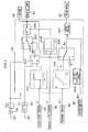
- FIG. 1 is a circuit diagram showing the structure of the wheeled hydraulic excavator equipped with the failure detection device for a hydraulic motor according to the first embodiment of the present invention.
- FIG.2 is sectional view of a traveling motor to which the present invention has been applied.
- FIG. 3 schematically illustrates the details of a controller which constitutes the failure detection device according to the first embodiment of the present invention.
- FIG. 4 is a flow chart showing an example of procedure executed by the controller.
- FIG. 5 is a circuit diagram showing the structure of the wheeled hydraulic excavator equipped with the failure detection device for the hydraulic motor according to the second embodiment of the present invention.
- FIG. 6 schematically illustrates the details of a controller which constitutes the failure detection device according to the second embodiment of the present invention.
- FIG. 7 is a circuit diagram showing the structure of the wheeled hydraulic excavator equipped with the failure detection device for a hydraulic motor according to the third embodiment of the present invention.
- FIG. 8 schematically illustrates the details of the controller which constitutes the failure detection device according to the third embodiment of the present invention.
- FIG. 9 is a circuit diagram showing the structure of the wheeled hydraulic excavator equipped with the failure detection device for a hydraulic motor according to the fourth embodiment of the present invention.
- FIG. 10 schematically illustrates the details of the controller which constitutes the failure detection device according to the fourth embodiment of the present invention.
- the wheeled hydraulic excavator comprises a wheeled undercarriage upon which an upper-structure is rotatably mounted, and a working attachment is fitted to this upper-structure.
- a hydraulic motor 1 for traveling which is driven by a hydraulic circuit for traveling shown in FIG. 1 is provided in the undercarriage.
- hydraulic oil is discharged from a main pump 3 which is driven by an engine, the direction and flow rate of the discharged oil are controlled by a control valve 4, and then the hydraulic oil is supplied to a traveling motor 1 via a brake valve 6 with a built-in counterbalance valve 5.
- a transmission 7 is connected with an output shaft 1a of the traveling motor 1. The rotational speed of the traveling motor 1 is changed by the transmission 7, and is transmitted to tires 10 through propeller shafts 8 and axles 9. Thus, the wheeled hydraulic excavator is propelled.
- the pressure oil from the main pump 3 is also supplied to a hydraulic circuit for working which is not shown in the figure, and drives actuators for working.
- the direction of changeover and operation amount of the control valve 4 are controlled by pilot pressure from a pilot control circuit.
- the traveling speed of the vehicle can be controlled by controlling the amount by which the control valve 4 is operated.
- the pilot control circuit comprises a pilot pump 21, a traveling pilot valve 23 that generates a secondary pilot pressure P1 according to the amount by which an accelerator pedal 22 is stepped upon, a slow-return valve 24 that delays oil returning to the pilot valve 23, and a forward/reverse switchover valve 25 which is used for selecting forward traveling, reverse traveling or neutral for the vehicle.
- the forward/reverse switchover valve 25 is constituted of a solenoid-controlled directional control valve, and its position is changed over by operating a switch not shown in the figures.
- FIG. 1 shows the condition with the forward/reverse switchover valve 25 in its neutral (N) position, and moreover when the traveling pilot valve 23 is not being operated. Accordingly, the control valve 4 is in its neutral position, the pressure oil from the main pump 3 returns to a reservoir, and the vehicle remains stopped.
- the forward/reverse switchover valve 25 is switched to its forward traveling position (F position) or to its reverse traveling position (R position) by the operation of the switch, and then the accelerator pedal 22 is stepped upon, the secondary pressure P1 according to the amount by which the accelerator pedal is operated acts on a pilot port of the control valve 4.
- the control valve 4 is operated by the operation amount corresponding to the secondary pilot pressure P1.
- the discharged oil from the main pump 3 is led to the traveling motor 1 via the control valve 4, a center joint 12 and the brake valve 6, so as to drive the traveling motor 1.
- the leakage oil from the traveling motor 1 is collected to the reservoir through a drain line (drain chamber) 11.
- the traveling motor 1 changes over from motor action to pump action, in which its B port is its suction (inlet) port and its A port is its discharge (outlet) port in FIG. 1.
- Flow of the pressure oil from the traveling motor 1 is restricted by the restriction of the counterbalance valve 5 (neutral restriction), the pressure between the counterbalance valve 5 and the traveling motor 1 then rises and acts on the traveling motor 1 as brake pressure.
- the traveling motor 1 generates the brake torque to slow the vehicle down. If, during the pump operation, the quantity of oil flowing into the traveling motor 1 becomes insufficient, the additional oil is supplied from a make-up port 13 thereto.
- the maximum brake pressure is regulated by relief valves 14 and 15.
- a governor 2a of the engine 2 is connected with a pulse motor 32 via a link mechanism 31, and the rotational speed of engine 2 is controlled by rotation of the pulse motor 32. In particular, the engine speed is increased by the normal rotation of the pulse motor 32, while it is decreased by the reverse rotation of the pulse motor.
- a potentiometer 33 is connected with the governor 2a via the link mechanism 31, and this potentiometer 33 detects a governor lever angle corresponding to the rotational speed of the engine 2. The detected value is input to the controller 30 as a control rotational speed N ⁇ .
- the controller 30 is connected with a speed sensor 26 that detects the vehicle speed, a pressure sensor 34 that detects the secondary pilot pressure P1 generated by the traveling pilot valve 23 corresponding to the pedal operation amount, a fluid level sensor 35 that detects the oil level in the transmission 7, a reset switch 36, and an ignition key switch 37 that is turned on/off according to the operation of an ignition key, respectively.
- the fluid level sensor 35 is a limit switch, the limit switch 35 is turned on by a float 35a when the oil level in the transmission reaches a predetermined value La which is set in advance.
- a power source 38 is connected with the key switch 37, and the electrical power is supplied to the controller 30 in response to the key switch 37 being turned on. Accordingly, the controller 30 implements calculations as will be described later, to control the rotation of the pulse motor 32 by outputting the control signal to the pulse motor 32 and also to control operations of a buzzer 39 and a warning lamp 40 (which together are referred to as a warning device) by outputting control signals thereto.
- FIG. 2 is a sectional view of the variable displacement traveling motor 1.
- a plurality of pistons 42 (only one of which is shown in the figure) are connected with a flange 41 of the output shaft 1a of the traveling motor 1, along its circumferential direction.
- the pistons 42 are slidably inserted into oil chambers 43a formed in a cylinder block 43 through piston rings 42a.
- the end of the cylinder block 43 comes into contact with a swash plate 44, and their contacting surfaces mutually define a circular cone shape.
- the swash plate 44 can be swung or inclined together with the cylinder block 43 in the direction of the arrow shown in the figure, and the motor displacement varies according to the swing amount or inclined angle of the swash plate.
- An inlet or suction port and an outlet or delivery port of oil are provided in the swash plate and a motor cover 45 which is in contact with the swash plate 44, the suction port and the delivery port extending over half a phase, respectively.
- the pressure oil from main pump 3 flows into the oil chambers 43a through the suction port, while the oil from the oil chambers 43a flows out to the reservoir through the delivery port. Due to this, the pistons 42 are slid within the oil chambers 43a, and, while the swash plate 44 is kept in contact with the cylinder block 43, the output shaft 1a of the motor 1 rotates as a unit with the cylinder block 43 and the pistons 42.
- An input shaft 7a of the transmission 7 is connected by splines with the motor output shaft 1a so that the rotation of the traveling motor 1 is transmitted to the transmission 7.
- portions of the pressure oil which is supplied to the oil chambers 43a from the main pump 3 leaks into the drain chamber 11 through gaps between the mutually contacting surfaces of the swash plate 44 and the cylinder block 43, or gaps between the mutually sliding surfaces of the pistons 42 and the oil chambers 43a.
- This leakage oil returns to the reservoir via a drain hole 11a which is provided in the bottom of the motor casing 46, while the oil is prevented from flowing into the transmission chamber 7b from the drain chamber 11 by seal rings SR.
- this type of abnormal operation of the traveling motor 1 is detected with a vehicle speed sensor 26 and a fluid level sensor 35, and such abnormal state is responded as follows.
- FIG. 3 is a schematic illustration to explain details of the controller 30.
- the ignition key switch 37 When the ignition key switch 37 is turned on, the electric power is supplied to the controller 30 to start execution of its processing.
- a function generator 301 outputs a set signal to a set terminal S of a RS flip-flop 302 when the fluid level sensor 35 is switched on, that is, when the oil level in the transmission chamber 7b is equal to or greater than the predetermined value La.
- the value La in this case, is set to correspond to rise of the oil level due to the breakdown of the motor 1, as described above, so that when the oil level reaches the value La, it may be determined that the traveling motor 1 has broken down.
- the flip-flop 302 When the set signal is input to the set terminal S of the flip-flop 302, the flip-flop 302 outputs a high-level signal from its terminal Q to change over a switchover circuit 303 to its contact "a" side.
- a function generator 308 When the vehicle speed detected by the speed sensor 26 is equal to or lower than a predetermined value (which may equal zero), in other words, when the vehicle has stopped, a function generator 308 outputs a close signal to close a changeover switch 309. As a result, electrical power is supplied to a buzzer 39 and a warning lamp 40, so that the buzzer emits sound and the warning lamp 40 is illuminated.
- the reset switch 36 When a reset switch 36 is turned on, the reset switch 36 outputs a reset signal to a reset terminal R of the flip-flop 302.
- the flip-flop 302 sets low-level in the terminal Q in response to this reset signal, and the switchover circuit 303 is then switched to its contact "b" side.
- the supply of electrical power to the buzzer 39 and the warning lamp 40 is interrupted so that the buzzer sound is brought to a halt and the warning lamp 40 is extinguished.
- an open signal is output to the changeover switch 309 to open the changeover switch 309. Also in this case, the buzzer sound is stopped, and the warning lamp 40 is turned off.
- a function by which the engine speed should increase along with increase of the traveling pilot pressure is set in advance in the function generator 304, as schematically shown in the figure.
- the function generator 304 sets the rotational speed N corresponding to the detected value P1 from the pressure sensor 34 based upon this function, and outputs this set value N to a switchover circuit 305.
- the switchover circuit 303 is switched to its contact "a" side and also the changeover switch 309 is closed, the switchover circuit 305 is switched to its contact "a" side.
- the switchover circuit 303 is switched to its contact "b" side and also the changeover switch 309 is open, the switchover circuit 305 is switched to its contact "b" side.
- the switchover circuit 305 selects either the rotational speed N as set by the function generator 304 or an idling rotational speed Ni which is set in advance in a rotational speed setting device 306, and outputs its selected rotational speed to a servo control section 307 as a target rotational speed Ny.
- the target rotational speed Ny is compared with the control rotational speed N ⁇ which corresponds to the amount of displacement of the governor lever as detected by the potentiometer 33, and the pulse motor 32 is controlled so as to bring the control rotational speed N ⁇ to match the target rotational speed Ny, according to the procedure shown in FIG. 4.
- step S21 the rotational speed command value Ny and the control rotational speed N ⁇ are read in, and then the flow of control proceeds to step S22.
- step S22 Ny is subtracted from N ⁇ and the result of this subtraction, i.e. the rotational speed differential A, is stored in a memory.
- step S23 using a predetermined standard rotational speed differential K set in advance, it makes a decision as to whether or not
- step S25 a signal for instructing reverse rotation of the motor is output to the pulse motor 32 in order to reduce the engine speed.
- the pulse motor 32 is caused to rotate in reverse so that the rotational speed of the engine 2 drops.
- step S26 a signal for instructing normal rotation of the motor is output in order to increase the engine speed.
- step S27 the flow of control proceeds to step S27 to output a motor stop signal. Therefore, the rotational speed of the engine 2 is maintained constant.
- the function generator 301 outputs the set signal to the set terminal of the flip-flop 302 so that the switchover circuit 303 is switched to its contact "a" side in response to a high level signal output from the Q terminal of the flip-flop 302.
- the changeover switch 309 is closed so that warning lamp 40 is illuminated, as well as the buzzer sound being emitted. Accordingly, the operator becomes aware of an abnormal state of the traveling motor 1, and is able to perform an appropriate operation, e.g. to stop the engine, in response to such abnormal state of the motor 1.
- the switchover circuit 305 is switched to the contact "a" side. Due to this, the engine speed is lowered to its idling rotational speed Ni, and the motor rotational speed also drops in line with reduction in amount of the delivery oil from the pump. As a result, the quantity of oil flow into the drain chamber 11 decreases, so that it becomes possible to minimize the leakage of oil from the drain chamber 11 to the transmission chamber 7b. Moreover, useless consumption of fuel can be prevented. It should be understood that the oil collected in the transmission chamber 7b can be exhausted through a drain hole not shown in the figures, and thereby it is possible to regulate the oil level in the transmission chamber 7b within the predetermined value.
- traveling motor 1 If the traveling motor 1 is damaged heavily and driving the vehicle under its own power is difficult or impossible, it may be pulled up on the trailer by engaging the end of a bucket of the hydraulic excavator with part of the trailer and then actuating hydraulic cylinders for a boom or arm.
- a failure of the traveling motor 1 is detected when the oil level in the transmission chamber 7b has reached the predetermined value La while the vehicle stops, and then the warning devices 39 and 40 are caused to operate. Therefore, it is possible for an operator to be made aware of abnormal operation of the traveling motor 1 at an early stage, and to respond appropriately to such abnormal circumstances. In this case, if a period of time is required before the oil level becomes steady, it may be possible to detect a failure of the traveling motor 1 based on the value detected by the fluid level sensor 35 after such a period of time.
- the engine speed is lowered to the idling rotation speed Ni to restrict the drive of the traveling motor 1 when a breakdown of the motor 1 is detected. Therefore, the quantity of oil flow into the drain chamber 11 is reduced irrespective of operation amount of the accelerator pedal 22, and it is possible to prevent oil leakage into the transmission chamber 7b.
- the warning devices 39 and 40 continue to be operated and the restriction upon traveling of the vehicle is maintained until the reset switch 36 is actuated or the ignition key switch 37 is turned off when the oil level in the transmission chamber 7b has dropped to the predefined value La or lower. Therefore, it is possible that an operator is reliably made aware of the abnormal operation in the traveling motor 1.
- the restriction upon the traveling of the vehicle has been cancelled, the engine speed can again be increased according to the operation of the accelerator pedal and it is possible to load the vehicle upon the trailer or the like easily.
- FIG. 5 is a circuit diagram showing the structure of a wheeled hydraulic excavator which is equipped with a failure detection device according to the second embodiment
- FIG. 6 schematically illustrates details of a controller 30A according to the second embodiment. It should be noted that the same reference numerals are used for elements similar to that of FIGS. 1 and 3, and the explanation will focus on the points different therefrom.
- the line between the traveling pilot valve 23 and the slow-return valve 24 can be connected with the reservoir through a solenoid valve 47.
- the solenoid valve 47 is controlled by a control signal from the controller 30A.
- a solenoid 47a of the solenoid valve 47 is connected with the changeover switch 309.
- the switchover circuit 303 and 305 are switched to the contact "b" side, respectively. Accordingly, the solenoid 47a is demagnetized, and the solenoid valve 47 is switched to its position A. As a result, the traveling pilot pressure corresponding to the operation of the accelerator pedal is made to act on the pilot port of the control valve 4, and the supply of the pressure oil to the traveling motor 1 becomes possible.
- the traveling pilot pressure is made to return to the reservoir by the operation of the solenoid valve 47. Therefore, even if the accelerator pedal 22 is actuated, the traveling motor 1 continues to be prevented from rotating, and thereafter it is possible to prevent further oil leakage into the drain chamber 11.
- FIG. 7 is a circuit diagram showing the construction of a wheeled hydraulic excavator which is equipped with a failure detection device according to the third embodiment
- FIG. 8 schematically illustrates the structure of a controller 30B according to the third embodiment. It should be noted the same reference numerals are used for elements similar to that of the FIGS. 1 and 3, and the explanation will focus upon the points different therefrom.
- a starting motor 48 is connected with the controller 30B, and the drive of the starting motor 48 is controlled thereby.
- the ignition key switch 37 is connected with the starting motor 48 via a relay 310, and the output terminal of the changeover switch 309 is connected with the coil of the relay 310.
- the switchover circuit 303 When, in such a state, the reset switch 36 is actuated, the switchover circuit 303 is switched to the contact "b" side, and the supply of electricity to the coil of the relay 310 is intercepted. The relay contact is thus switched to the contact "R2" side, which makes possible to restart the engine 2. It should be noted that it would also be possible to restart the engine 2, as an alternative to operation of the reset switch 36, by a repairman, etc. using some apparatuses to supply an external signal of some type. In this manner, it would be impossible for an operator to restart the engine upon his own decision.
- the engine 2 when a failure of the traveling motor 1 is detected, the engine 2 can not be restarted. Therefore, an operator will not imprudently restart the engine 2 to drive the vehicle, and it is possible to ensure that he makes an appropriate response to the abnormal operation of the traveling motor 1.
- FIG. 9 is a circuit diagram showing the structure of a wheeled hydraulic excavator equipped with a failure detection device according to the fourth embodiment
- FIG. 10 schematically illustrates details of a controller 30C according to the fourth embodiment. It should be noted that the same reference numerals are used for elements similar to that of FIGS. 1 and 3, and the explanations will focus on the points different therefrom.
- a forward/reverse changing switch 49 for outputting a switching command to the forward/reverse switchover valve 25, and a brake switch 50 for outputting an operate command to a work brake not shown in the figures are also connected to the controller 30C.
- a switchover circuit 311 is connected with the terminal Q of the flip-flop 302, and the switchover circuit 311 is switched according to a signal from a work detection section 312. The signals from the forward/reverse changing switch 49 and the brake switch 50 are input to the work detection section 312.
- the work detection section 312 sets the switchover circuit 311 to the contact "a" side when the forward/reverse switchover valve 25 is in the neutral position and also the work brake is being operated, while in other conditions, the switchover circuit 311 is switched to the contact "b" side.
- the switchover circuit 311 is switched to the contact "b" in any conditions other than the working state, and the switchover circuits 303 and 305 are switched to the contact "a" side if a failure of the traveling motor 1 occurs, to restrict the engine speed to the idling rotational speed Ni.
- the forward/reverse switchover valve 25 is set to the neutral position in response to the operation of the forward/reverse changing switch 49, and also the work brake is operated by the operation of the brake switch 50, the switchover circuit 311 is then switched to the contact "a" side.
- the switchover circuits 303 and 305 are both switched to the contact "b" side to cancel the restriction of the engine speed.
- the fourth embodiment it is detected as to whether or not the vehicle has started the work operation according to actuation of the forward/reverse changing switch 49 and the brake switch 50. It is possible to continue working in the normal manner even when the traveling motor 1 has broken down since the restriction on the engine speed is disabled during working. It should be noted that the fourth embodiment can be applied, not only to a system which restricts the engine speed during a failure of the traveling motor 1, but also, in the same manner, to systems which control the vehicle traveling in other ways, such as by stopping the vehicle traveling, by preventing the engine from restarting, or by causing the parking brake to operate. In other words, the above restrictions upon traveling may be cancelled during working.
- the fluid level sensor 35 could be implemented, not as a switch, but as a sensor which detects the fluid level continuously and outputs a set signal to the flip-flop 302 when the oil level exceeds the predefined value La.
- the buzzer sound is emitted along with the illumination of the warning lamp 40 when the traveling motor 1 has broken down, it would also be acceptable to provide one of the warning devices.
- the traveling motor 1 upon a failure of the traveling motor 1, the provision of warning and the restriction of the vehicle traveling have been performed at the same time, it would also be acceptable to perform only one of them.
- the driving of the traveling motor 1 is limited during a failure of the traveling motor 1, driving of other actuators, such as a swing motor, may as well be restricted.
- failure detection device for a hydraulic motor has been explained in terms of application to a wheeled hydraulic excavator by way of example, it would also be possible, in the same manner, to apply the failure detection device of the hydraulic motor according to the present invention to a crawler hydraulic excavator, or to other kinds of hydraulic drive vehicles.
Landscapes
- Engineering & Computer Science (AREA)
- General Engineering & Computer Science (AREA)
- Mining & Mineral Resources (AREA)
- Civil Engineering (AREA)
- Structural Engineering (AREA)
- Mechanical Engineering (AREA)
- Physics & Mathematics (AREA)
- Fluid Mechanics (AREA)
- Fluid-Pressure Circuits (AREA)
Priority Applications (1)
| Application Number | Priority Date | Filing Date | Title |
|---|---|---|---|
| DE60140090T DE60140090D1 (de) | 2001-01-19 | 2001-01-19 | Hydraulikmotor-Störungsdetektor und hydraulisch angetriebenes Fahrzeug |
Applications Claiming Priority (1)
| Application Number | Priority Date | Filing Date | Title |
|---|---|---|---|
| EP01901480A EP1361379B1 (fr) | 2001-01-19 | 2001-01-19 | Detecteur d'anomalies dans un moteur hydraulique et vehicule a commande hydraulique |
Related Parent Applications (1)
| Application Number | Title | Priority Date | Filing Date |
|---|---|---|---|
| EP01901480A Division EP1361379B1 (fr) | 2001-01-19 | 2001-01-19 | Detecteur d'anomalies dans un moteur hydraulique et vehicule a commande hydraulique |
Publications (2)
| Publication Number | Publication Date |
|---|---|
| EP1881241A1 true EP1881241A1 (fr) | 2008-01-23 |
| EP1881241B1 EP1881241B1 (fr) | 2009-09-30 |
Family
ID=38692002
Family Applications (1)
| Application Number | Title | Priority Date | Filing Date |
|---|---|---|---|
| EP07118393A Expired - Lifetime EP1881241B1 (fr) | 2001-01-19 | 2001-01-19 | Détecteur d'anomalies dans un moteur hydraulique et véhicule à entrainement hydraulique |
Country Status (2)
| Country | Link |
|---|---|
| EP (1) | EP1881241B1 (fr) |
| DE (1) | DE60140090D1 (fr) |
Cited By (3)
| Publication number | Priority date | Publication date | Assignee | Title |
|---|---|---|---|---|
| EP3578721A4 (fr) * | 2017-02-10 | 2020-11-04 | Doosan Infracore Co., Ltd. | Appareil de sécurité de machine de construction et procédé de commande |
| EP3581718A4 (fr) * | 2017-09-07 | 2020-12-16 | Hitachi Construction Machinery Co., Ltd. | Machine de travail hydraulique |
| CN112392942A (zh) * | 2020-11-13 | 2021-02-23 | 徐州徐工矿业机械有限公司 | 一种超大型液压挖掘机及其回转减速机齿轮油位监测装置 |
Citations (5)
| Publication number | Priority date | Publication date | Assignee | Title |
|---|---|---|---|---|
| US4409832A (en) * | 1980-07-09 | 1983-10-18 | Fiat Auto S.P.A. | Device for automatically indicating an insufficient level of automatic fluid |
| WO1993013340A1 (fr) | 1991-12-23 | 1993-07-08 | Caterpillar Inc. | Systeme de controle diagnostique pour vehicule |
| EP0589507A2 (fr) | 1992-09-22 | 1994-03-30 | General Motors Corporation | Appareil et procédé pour la détermination du niveau du liquide dans des transmissions automatiques |
| US5343779A (en) * | 1989-07-14 | 1994-09-06 | Zahnradfabrik Friedrichshafen Ag | Arrangement and process for operating a fail safe braking system in a continuously variable driving unit of a motor vehicle |
| US5842144A (en) | 1995-06-07 | 1998-11-24 | Caterpillar Inc. | Default mode control system for a split torque transmission |
-
2001
- 2001-01-19 EP EP07118393A patent/EP1881241B1/fr not_active Expired - Lifetime
- 2001-01-19 DE DE60140090T patent/DE60140090D1/de not_active Expired - Lifetime
Patent Citations (5)
| Publication number | Priority date | Publication date | Assignee | Title |
|---|---|---|---|---|
| US4409832A (en) * | 1980-07-09 | 1983-10-18 | Fiat Auto S.P.A. | Device for automatically indicating an insufficient level of automatic fluid |
| US5343779A (en) * | 1989-07-14 | 1994-09-06 | Zahnradfabrik Friedrichshafen Ag | Arrangement and process for operating a fail safe braking system in a continuously variable driving unit of a motor vehicle |
| WO1993013340A1 (fr) | 1991-12-23 | 1993-07-08 | Caterpillar Inc. | Systeme de controle diagnostique pour vehicule |
| EP0589507A2 (fr) | 1992-09-22 | 1994-03-30 | General Motors Corporation | Appareil et procédé pour la détermination du niveau du liquide dans des transmissions automatiques |
| US5842144A (en) | 1995-06-07 | 1998-11-24 | Caterpillar Inc. | Default mode control system for a split torque transmission |
Cited By (4)
| Publication number | Priority date | Publication date | Assignee | Title |
|---|---|---|---|---|
| EP3578721A4 (fr) * | 2017-02-10 | 2020-11-04 | Doosan Infracore Co., Ltd. | Appareil de sécurité de machine de construction et procédé de commande |
| US11377821B2 (en) | 2017-02-10 | 2022-07-05 | Doosan Infracore Co., Ltd. | Construction machine safety apparatus and controlling method |
| EP3581718A4 (fr) * | 2017-09-07 | 2020-12-16 | Hitachi Construction Machinery Co., Ltd. | Machine de travail hydraulique |
| CN112392942A (zh) * | 2020-11-13 | 2021-02-23 | 徐州徐工矿业机械有限公司 | 一种超大型液压挖掘机及其回转减速机齿轮油位监测装置 |
Also Published As
| Publication number | Publication date |
|---|---|
| DE60140090D1 (de) | 2009-11-12 |
| EP1881241B1 (fr) | 2009-09-30 |
Similar Documents
| Publication | Publication Date | Title |
|---|---|---|
| EP1881240B1 (fr) | Détecteur d'anomalies dans un moteur hydraulique et véhicule à éntrainement hydraulique | |
| US7082756B2 (en) | Device for detecting failure of hydraulic motor, and hydraulic vehicle | |
| EP1544440B1 (fr) | Contrôleur du moteur d'un engin de travaux. | |
| EP1361379B1 (fr) | Detecteur d'anomalies dans un moteur hydraulique et vehicule a commande hydraulique | |
| US7506717B2 (en) | Hydraulically driven vehicle | |
| EP1881241B1 (fr) | Détecteur d'anomalies dans un moteur hydraulique et véhicule à entrainement hydraulique | |
| JP6682496B2 (ja) | 作業機の油圧システム | |
| JP2868592B2 (ja) | 油圧駆動車両の原動機回転数制御装置 | |
| RU2638991C2 (ru) | Система и способ управления температурой машины | |
| KR100974282B1 (ko) | 휠타입 건설기계의 인양 시스템 | |
| JPH11336134A (ja) | 建設機械の旋回体ブレーキ装置 | |
| KR19990059485A (ko) | 유압식 건설기계의 엔진 출력 제어장치 및 그 제어방법 | |
| JP2005076683A (ja) | 建設機械の油圧ポンプ出力制御回路 | |
| KR20080020403A (ko) | 유압구동차량용 주행모터 토크 제어회로 | |
| KR19980067342A (ko) | 로우더의 엔진펌프 제어장치 | |
| KR19980068184U (ko) | 휠로우더의 주행 피칭 감쇄장치 |
Legal Events
| Date | Code | Title | Description |
|---|---|---|---|
| PUAI | Public reference made under article 153(3) epc to a published international application that has entered the european phase |
Free format text: ORIGINAL CODE: 0009012 |
|
| 17P | Request for examination filed |
Effective date: 20071012 |
|
| AC | Divisional application: reference to earlier application |
Ref document number: 1361379 Country of ref document: EP Kind code of ref document: P |
|
| AK | Designated contracting states |
Kind code of ref document: A1 Designated state(s): DE FR GB IT NL |
|
| AKX | Designation fees paid |
Designated state(s): DE FR GB IT NL |
|
| GRAP | Despatch of communication of intention to grant a patent |
Free format text: ORIGINAL CODE: EPIDOSNIGR1 |
|
| GRAS | Grant fee paid |
Free format text: ORIGINAL CODE: EPIDOSNIGR3 |
|
| GRAA | (expected) grant |
Free format text: ORIGINAL CODE: 0009210 |
|
| AC | Divisional application: reference to earlier application |
Ref document number: 1361379 Country of ref document: EP Kind code of ref document: P |
|
| AK | Designated contracting states |
Kind code of ref document: B1 Designated state(s): DE FR GB IT NL |
|
| REG | Reference to a national code |
Ref country code: GB Ref legal event code: FG4D |
|
| REF | Corresponds to: |
Ref document number: 60140090 Country of ref document: DE Date of ref document: 20091112 Kind code of ref document: P |
|
| NLV1 | Nl: lapsed or annulled due to failure to fulfill the requirements of art. 29p and 29m of the patents act | ||
| PG25 | Lapsed in a contracting state [announced via postgrant information from national office to epo] |
Ref country code: NL Free format text: LAPSE BECAUSE OF FAILURE TO SUBMIT A TRANSLATION OF THE DESCRIPTION OR TO PAY THE FEE WITHIN THE PRESCRIBED TIME-LIMIT Effective date: 20090930 |
|
| PLBE | No opposition filed within time limit |
Free format text: ORIGINAL CODE: 0009261 |
|
| STAA | Information on the status of an ep patent application or granted ep patent |
Free format text: STATUS: NO OPPOSITION FILED WITHIN TIME LIMIT |
|
| 26N | No opposition filed |
Effective date: 20100701 |
|
| REG | Reference to a national code |
Ref country code: FR Ref legal event code: ST Effective date: 20100930 |
|
| PG25 | Lapsed in a contracting state [announced via postgrant information from national office to epo] |
Ref country code: FR Free format text: LAPSE BECAUSE OF NON-PAYMENT OF DUE FEES Effective date: 20100201 |
|
| PG25 | Lapsed in a contracting state [announced via postgrant information from national office to epo] |
Ref country code: IT Free format text: LAPSE BECAUSE OF FAILURE TO SUBMIT A TRANSLATION OF THE DESCRIPTION OR TO PAY THE FEE WITHIN THE PRESCRIBED TIME-LIMIT Effective date: 20090930 |
|
| PGFP | Annual fee paid to national office [announced via postgrant information from national office to epo] |
Ref country code: GB Payment date: 20140115 Year of fee payment: 14 |
|
| PGFP | Annual fee paid to national office [announced via postgrant information from national office to epo] |
Ref country code: DE Payment date: 20150113 Year of fee payment: 15 |
|
| GBPC | Gb: european patent ceased through non-payment of renewal fee |
Effective date: 20150119 |
|
| PG25 | Lapsed in a contracting state [announced via postgrant information from national office to epo] |
Ref country code: GB Free format text: LAPSE BECAUSE OF NON-PAYMENT OF DUE FEES Effective date: 20150119 |
|
| REG | Reference to a national code |
Ref country code: DE Ref legal event code: R119 Ref document number: 60140090 Country of ref document: DE |
|
| PG25 | Lapsed in a contracting state [announced via postgrant information from national office to epo] |
Ref country code: DE Free format text: LAPSE BECAUSE OF NON-PAYMENT OF DUE FEES Effective date: 20160802 |