EP1881274A2 - Appareil de filtrage d'air ayant un mécanisme de suppression de matériau étranger - Google Patents
Appareil de filtrage d'air ayant un mécanisme de suppression de matériau étranger Download PDFInfo
- Publication number
- EP1881274A2 EP1881274A2 EP07013837A EP07013837A EP1881274A2 EP 1881274 A2 EP1881274 A2 EP 1881274A2 EP 07013837 A EP07013837 A EP 07013837A EP 07013837 A EP07013837 A EP 07013837A EP 1881274 A2 EP1881274 A2 EP 1881274A2
- Authority
- EP
- European Patent Office
- Prior art keywords
- water
- electrolytic water
- electrolytic
- filtering apparatus
- gas
- Prior art date
- Legal status (The legal status is an assumption and is not a legal conclusion. Google has not performed a legal analysis and makes no representation as to the accuracy of the status listed.)
- Withdrawn
Links
- 239000000463 material Substances 0.000 title claims abstract description 123
- 238000001914 filtration Methods 0.000 title claims abstract description 96
- 230000007246 mechanism Effects 0.000 title claims abstract description 29
- XLYOFNOQVPJJNP-UHFFFAOYSA-N water Substances O XLYOFNOQVPJJNP-UHFFFAOYSA-N 0.000 claims abstract description 517
- 239000007788 liquid Substances 0.000 claims abstract description 119
- 238000007664 blowing Methods 0.000 claims abstract description 24
- QVGXLLKOCUKJST-UHFFFAOYSA-N atomic oxygen Chemical compound [O] QVGXLLKOCUKJST-UHFFFAOYSA-N 0.000 claims description 36
- 239000001301 oxygen Substances 0.000 claims description 36
- 229910052760 oxygen Inorganic materials 0.000 claims description 36
- -1 chlorine ions Chemical class 0.000 claims description 23
- MHAJPDPJQMAIIY-UHFFFAOYSA-N Hydrogen peroxide Chemical compound OO MHAJPDPJQMAIIY-UHFFFAOYSA-N 0.000 claims description 20
- QWPPOHNGKGFGJK-UHFFFAOYSA-N hypochlorous acid Chemical compound ClO QWPPOHNGKGFGJK-UHFFFAOYSA-N 0.000 claims description 15
- CBENFWSGALASAD-UHFFFAOYSA-N Ozone Chemical compound [O-][O+]=O CBENFWSGALASAD-UHFFFAOYSA-N 0.000 claims description 11
- 239000000460 chlorine Substances 0.000 claims description 11
- 229910052801 chlorine Inorganic materials 0.000 claims description 11
- 230000008021 deposition Effects 0.000 claims description 8
- 238000007599 discharging Methods 0.000 claims description 8
- 230000001737 promoting effect Effects 0.000 claims description 8
- 238000011144 upstream manufacturing Methods 0.000 claims description 8
- VYPSYNLAJGMNEJ-UHFFFAOYSA-N Silicium dioxide Chemical compound O=[Si]=O VYPSYNLAJGMNEJ-UHFFFAOYSA-N 0.000 claims description 7
- 239000008119 colloidal silica Substances 0.000 claims description 5
- 239000000126 substance Substances 0.000 claims description 5
- 238000005086 pumping Methods 0.000 claims 1
- 238000012423 maintenance Methods 0.000 description 35
- 239000008399 tap water Substances 0.000 description 26
- 235000020679 tap water Nutrition 0.000 description 26
- 238000010276 construction Methods 0.000 description 23
- 239000007921 spray Substances 0.000 description 15
- 241000700605 Viruses Species 0.000 description 11
- 238000005868 electrolysis reaction Methods 0.000 description 11
- 239000002198 insoluble material Substances 0.000 description 9
- QJZYHAIUNVAGQP-UHFFFAOYSA-N 3-nitrobicyclo[2.2.1]hept-5-ene-2,3-dicarboxylic acid Chemical compound C1C2C=CC1C(C(=O)O)C2(C(O)=O)[N+]([O-])=O QJZYHAIUNVAGQP-UHFFFAOYSA-N 0.000 description 8
- VTYYLEPIZMXCLO-UHFFFAOYSA-L Calcium carbonate Chemical compound [Ca+2].[O-]C([O-])=O VTYYLEPIZMXCLO-UHFFFAOYSA-L 0.000 description 8
- 238000000151 deposition Methods 0.000 description 8
- 239000004021 humic acid Substances 0.000 description 8
- 238000006243 chemical reaction Methods 0.000 description 6
- 238000010586 diagram Methods 0.000 description 6
- 229920005989 resin Polymers 0.000 description 6
- 239000011347 resin Substances 0.000 description 6
- 229910000019 calcium carbonate Inorganic materials 0.000 description 4
- ZLNQQNXFFQJAID-UHFFFAOYSA-L magnesium carbonate Chemical compound [Mg+2].[O-]C([O-])=O ZLNQQNXFFQJAID-UHFFFAOYSA-L 0.000 description 4
- 239000001095 magnesium carbonate Substances 0.000 description 4
- 229910000021 magnesium carbonate Inorganic materials 0.000 description 4
- 229920000139 polyethylene terephthalate Polymers 0.000 description 4
- 239000005020 polyethylene terephthalate Substances 0.000 description 4
- 238000011045 prefiltration Methods 0.000 description 4
- 241000712461 unidentified influenza virus Species 0.000 description 4
- 241000894006 Bacteria Species 0.000 description 3
- OYPRJOBELJOOCE-UHFFFAOYSA-N Calcium Chemical compound [Ca] OYPRJOBELJOOCE-UHFFFAOYSA-N 0.000 description 3
- BHPQYMZQTOCNFJ-UHFFFAOYSA-N Calcium cation Chemical compound [Ca+2] BHPQYMZQTOCNFJ-UHFFFAOYSA-N 0.000 description 3
- KZBUYRJDOAKODT-UHFFFAOYSA-N Chlorine Chemical compound ClCl KZBUYRJDOAKODT-UHFFFAOYSA-N 0.000 description 3
- 241000233866 Fungi Species 0.000 description 3
- JLVVSXFLKOJNIY-UHFFFAOYSA-N Magnesium ion Chemical compound [Mg+2] JLVVSXFLKOJNIY-UHFFFAOYSA-N 0.000 description 3
- 239000011575 calcium Substances 0.000 description 3
- 229910052791 calcium Inorganic materials 0.000 description 3
- 229910001424 calcium ion Inorganic materials 0.000 description 3
- XLYOFNOQVPJJNP-ZSJDYOACSA-N heavy water Substances [2H]O[2H] XLYOFNOQVPJJNP-ZSJDYOACSA-N 0.000 description 3
- 208000015181 infectious disease Diseases 0.000 description 3
- 229910001425 magnesium ion Inorganic materials 0.000 description 3
- 230000001590 oxidative effect Effects 0.000 description 3
- 239000002245 particle Substances 0.000 description 3
- BASFCYQUMIYNBI-UHFFFAOYSA-N platinum Substances [Pt] BASFCYQUMIYNBI-UHFFFAOYSA-N 0.000 description 3
- 238000009834 vaporization Methods 0.000 description 3
- 230000008016 vaporization Effects 0.000 description 3
- FYYHWMGAXLPEAU-UHFFFAOYSA-N Magnesium Chemical compound [Mg] FYYHWMGAXLPEAU-UHFFFAOYSA-N 0.000 description 2
- 102000018697 Membrane Proteins Human genes 0.000 description 2
- 108010052285 Membrane Proteins Proteins 0.000 description 2
- 239000000919 ceramic Substances 0.000 description 2
- 238000004140 cleaning Methods 0.000 description 2
- 230000000531 effect on virus Effects 0.000 description 2
- 238000003780 insertion Methods 0.000 description 2
- 230000037431 insertion Effects 0.000 description 2
- 239000011777 magnesium Substances 0.000 description 2
- 229910052749 magnesium Inorganic materials 0.000 description 2
- 244000005700 microbiome Species 0.000 description 2
- 238000012986 modification Methods 0.000 description 2
- 230000004048 modification Effects 0.000 description 2
- 230000001954 sterilising effect Effects 0.000 description 2
- 235000020681 well water Nutrition 0.000 description 2
- 239000002349 well water Substances 0.000 description 2
- ZAMOUSCENKQFHK-UHFFFAOYSA-N Chlorine atom Chemical compound [Cl] ZAMOUSCENKQFHK-UHFFFAOYSA-N 0.000 description 1
- MYMOFIZGZYHOMD-UHFFFAOYSA-N Dioxygen Chemical compound O=O MYMOFIZGZYHOMD-UHFFFAOYSA-N 0.000 description 1
- 239000004743 Polypropylene Substances 0.000 description 1
- OUUQCZGPVNCOIJ-UHFFFAOYSA-M Superoxide Chemical compound [O-][O] OUUQCZGPVNCOIJ-UHFFFAOYSA-M 0.000 description 1
- RTAQQCXQSZGOHL-UHFFFAOYSA-N Titanium Chemical compound [Ti] RTAQQCXQSZGOHL-UHFFFAOYSA-N 0.000 description 1
- BZHJMEDXRYGGRV-UHFFFAOYSA-N Vinyl chloride Chemical compound ClC=C BZHJMEDXRYGGRV-UHFFFAOYSA-N 0.000 description 1
- 239000002253 acid Substances 0.000 description 1
- 238000009395 breeding Methods 0.000 description 1
- 230000001488 breeding effect Effects 0.000 description 1
- 230000015556 catabolic process Effects 0.000 description 1
- 239000001913 cellulose Substances 0.000 description 1
- 229920002678 cellulose Polymers 0.000 description 1
- 238000006731 degradation reaction Methods 0.000 description 1
- 230000003111 delayed effect Effects 0.000 description 1
- 238000004332 deodorization Methods 0.000 description 1
- 238000001514 detection method Methods 0.000 description 1
- 239000000428 dust Substances 0.000 description 1
- 230000000694 effects Effects 0.000 description 1
- 238000003411 electrode reaction Methods 0.000 description 1
- 229920000840 ethylene tetrafluoroethylene copolymer Polymers 0.000 description 1
- 238000001704 evaporation Methods 0.000 description 1
- 230000008020 evaporation Effects 0.000 description 1
- 239000004744 fabric Substances 0.000 description 1
- 239000007789 gas Substances 0.000 description 1
- TUJKJAMUKRIRHC-UHFFFAOYSA-N hydroxyl Chemical compound [OH] TUJKJAMUKRIRHC-UHFFFAOYSA-N 0.000 description 1
- 150000002500 ions Chemical class 0.000 description 1
- 229910052741 iridium Inorganic materials 0.000 description 1
- GKOZUEZYRPOHIO-UHFFFAOYSA-N iridium atom Chemical compound [Ir] GKOZUEZYRPOHIO-UHFFFAOYSA-N 0.000 description 1
- 230000007774 longterm Effects 0.000 description 1
- 229920011301 perfluoro alkoxyl alkane Polymers 0.000 description 1
- 229910052697 platinum Inorganic materials 0.000 description 1
- LEYNFUIKYCSXFM-UHFFFAOYSA-N platinum tantalum Chemical compound [Ta][Pt][Ta] LEYNFUIKYCSXFM-UHFFFAOYSA-N 0.000 description 1
- 229920013716 polyethylene resin Polymers 0.000 description 1
- 229920000098 polyolefin Polymers 0.000 description 1
- 229920001155 polypropylene Polymers 0.000 description 1
- 239000004810 polytetrafluoroethylene Substances 0.000 description 1
- 229920001343 polytetrafluoroethylene Polymers 0.000 description 1
- 239000002244 precipitate Substances 0.000 description 1
- 230000009257 reactivity Effects 0.000 description 1
- 238000011160 research Methods 0.000 description 1
- 239000000377 silicon dioxide Substances 0.000 description 1
- 241000894007 species Species 0.000 description 1
- 238000005507 spraying Methods 0.000 description 1
- 238000011146 sterile filtration Methods 0.000 description 1
- 230000009897 systematic effect Effects 0.000 description 1
- 238000012360 testing method Methods 0.000 description 1
- 238000012795 verification Methods 0.000 description 1
Images


Classifications
-
- F—MECHANICAL ENGINEERING; LIGHTING; HEATING; WEAPONS; BLASTING
- F24—HEATING; RANGES; VENTILATING
- F24F—AIR-CONDITIONING; AIR-HUMIDIFICATION; VENTILATION; USE OF AIR CURRENTS FOR SCREENING
- F24F8/00—Treatment, e.g. purification, of air supplied to human living or working spaces otherwise than by heating, cooling, humidifying or drying
- F24F8/10—Treatment, e.g. purification, of air supplied to human living or working spaces otherwise than by heating, cooling, humidifying or drying by separation, e.g. by filtering
- F24F8/117—Treatment, e.g. purification, of air supplied to human living or working spaces otherwise than by heating, cooling, humidifying or drying by separation, e.g. by filtering using wet filtering
- F24F8/125—Treatment, e.g. purification, of air supplied to human living or working spaces otherwise than by heating, cooling, humidifying or drying by separation, e.g. by filtering using wet filtering using wet filter elements
-
- A—HUMAN NECESSITIES
- A61—MEDICAL OR VETERINARY SCIENCE; HYGIENE
- A61L—METHODS OR APPARATUS FOR STERILISING MATERIALS OR OBJECTS IN GENERAL; DISINFECTION, STERILISATION OR DEODORISATION OF AIR; CHEMICAL ASPECTS OF BANDAGES, DRESSINGS, ABSORBENT PADS OR SURGICAL ARTICLES; MATERIALS FOR BANDAGES, DRESSINGS, ABSORBENT PADS OR SURGICAL ARTICLES
- A61L9/00—Disinfection, sterilisation or deodorisation of air
- A61L9/01—Deodorant compositions
- A61L9/014—Deodorant compositions containing sorbent material, e.g. activated carbon
-
- F—MECHANICAL ENGINEERING; LIGHTING; HEATING; WEAPONS; BLASTING
- F24—HEATING; RANGES; VENTILATING
- F24F—AIR-CONDITIONING; AIR-HUMIDIFICATION; VENTILATION; USE OF AIR CURRENTS FOR SCREENING
- F24F8/00—Treatment, e.g. purification, of air supplied to human living or working spaces otherwise than by heating, cooling, humidifying or drying
- F24F8/10—Treatment, e.g. purification, of air supplied to human living or working spaces otherwise than by heating, cooling, humidifying or drying by separation, e.g. by filtering
- F24F8/117—Treatment, e.g. purification, of air supplied to human living or working spaces otherwise than by heating, cooling, humidifying or drying by separation, e.g. by filtering using wet filtering
- F24F8/142—Treatment of used liquid, e.g. cleaning for recycling
-
- F—MECHANICAL ENGINEERING; LIGHTING; HEATING; WEAPONS; BLASTING
- F24—HEATING; RANGES; VENTILATING
- F24F—AIR-CONDITIONING; AIR-HUMIDIFICATION; VENTILATION; USE OF AIR CURRENTS FOR SCREENING
- F24F8/00—Treatment, e.g. purification, of air supplied to human living or working spaces otherwise than by heating, cooling, humidifying or drying
- F24F8/20—Treatment, e.g. purification, of air supplied to human living or working spaces otherwise than by heating, cooling, humidifying or drying by sterilisation
- F24F8/24—Treatment, e.g. purification, of air supplied to human living or working spaces otherwise than by heating, cooling, humidifying or drying by sterilisation using sterilising media
- F24F8/26—Treatment, e.g. purification, of air supplied to human living or working spaces otherwise than by heating, cooling, humidifying or drying by sterilisation using sterilising media using ozone
-
- F—MECHANICAL ENGINEERING; LIGHTING; HEATING; WEAPONS; BLASTING
- F24—HEATING; RANGES; VENTILATING
- F24F—AIR-CONDITIONING; AIR-HUMIDIFICATION; VENTILATION; USE OF AIR CURRENTS FOR SCREENING
- F24F8/00—Treatment, e.g. purification, of air supplied to human living or working spaces otherwise than by heating, cooling, humidifying or drying
- F24F8/80—Self-contained air purifiers
-
- F—MECHANICAL ENGINEERING; LIGHTING; HEATING; WEAPONS; BLASTING
- F24—HEATING; RANGES; VENTILATING
- F24F—AIR-CONDITIONING; AIR-HUMIDIFICATION; VENTILATION; USE OF AIR CURRENTS FOR SCREENING
- F24F6/00—Air-humidification, e.g. cooling by humidification
- F24F2006/006—Air-humidification, e.g. cooling by humidification with water treatment
-
- Y—GENERAL TAGGING OF NEW TECHNOLOGICAL DEVELOPMENTS; GENERAL TAGGING OF CROSS-SECTIONAL TECHNOLOGIES SPANNING OVER SEVERAL SECTIONS OF THE IPC; TECHNICAL SUBJECTS COVERED BY FORMER USPC CROSS-REFERENCE ART COLLECTIONS [XRACs] AND DIGESTS
- Y02—TECHNOLOGIES OR APPLICATIONS FOR MITIGATION OR ADAPTATION AGAINST CLIMATE CHANGE
- Y02A—TECHNOLOGIES FOR ADAPTATION TO CLIMATE CHANGE
- Y02A50/00—TECHNOLOGIES FOR ADAPTATION TO CLIMATE CHANGE in human health protection, e.g. against extreme weather
- Y02A50/20—Air quality improvement or preservation, e.g. vehicle emission control or emission reduction by using catalytic converters
Definitions
- the present invention relates to an air filtering apparatus that can remove microorganisms floating in the air (bacteria, virus, fungus, etc. (hereinafter referred to as "virus, etc.”).
- an air filtering apparatus for filtering air by using electrolytic water (for example, JP-A-2002-181358 ).
- water such as tap water or the like is electrolyzed to generate electrolytic water containing active oxygen species such as hypochlorous acid, etc., and the thus-generated electrolytic water is supplied to a humidification element (a filter element, a gas-liquid contact member or the like) formed of nonwoven cloth or the like.
- a humidification element a filter element, a gas-liquid contact member or the like
- virus, etc. in the air is brought into contact with the electrolytic water supplied to the humidification element to inactivate the virus, etc. while the air flows through the humidifying element, thereby filtering the air.
- the filtered air is made to flow to the outside of the apparatus.
- An object of the present invention is to provide an air filtering apparatus that can make a maintenance work easy and reduce the frequency of the maintenance.
- an air filtering apparatus comprises:
- the electrolytic water bath generates electrolytic water
- the electrolytic water supply unit supplies the electrolytic water to the gas-liquid contact member.
- the air blowing fan brings the indoor air sucked from the suction port of the housing into contact with the electrolytic water supplied (infiltrated, dropped or the like) to the gas-liquid contact member to filter the indoor air, and then blows out the filtered indoor air from the air blowing port.
- scales such as calcium carbonate, magnesium carbonate, etc. contained in the electrolytic water generated in the electrolytic bath, scales deposited from the electrolytic water, insoluble matters such as colloidal silica, humic acid, etc. (hereinafter referred to as "foreign materials”) can be removed at at least one place in the electrolytic water supply/circulating path by the foreign material removing mechanism. Therefore, the maintenance work can be facilitated, and the frequency of the maintenance work can be reduced.
- the foreign materials and the electrolytic water can be separated from each other and only the foreignmaterials can be withdrawn by the foreign material removing mechanism. Therefore, for example, it is unnecessary for a user or the like to withdraw scales, etc. by a manual labor or the like every time the scales, etc. are removed from electrodes, and thus the frequency of the maintenance can be reduced.
- the foreign material removing mechanism maybe equipped with a filter member that is freely detachably mounted in the electrolytic water supply unit and filters the electrolytic water introduced from the electrolytic bath, and the electrolytic water supply unit has an electrolytic water supply tray having an electrolytic water supply hole at the bottom portion thereof, the electrolytic water passing through the filter member being supplied to the gas-liquid contact member through the electrolytic water supply hole.
- the gas-liquid contact member is supplied with the electrolytic water from which the foreign materials are removed, and thus foreign materials such as scales, humic acid, etc. can be prevented from adhering to the gas-liquid contact member, and thus the frequency of the maintenance of the gas-liquid contact member can be reduced.
- the filter member may be configured to be freely detachable from the electrolytic water supply tray. Therefore, when the filter member is clogged with foreign materials, the filter member can be easily exchanged and thus the maintenance is easier.
- the filter member when the filter member is clogged, the water level of the electrolytic water in the electrolytic water supply tray increases. At this time, when it is detected by the water level sensor that the water level reaches the predetermined water level, the alarm unit alarms the exchange of the filter member to the user. Accordingly, the user, a maintenance manager or the like can be easily grasp the exchange timing of the filter member, that is, the maintenance timing.
- the electrolytic water supply unit has a bypass path for supplying the gas-liquid contact member with electrolytic water over-flowing from the electrolytic water supply tray.
- the air filtering apparatus when the filter member is clogged with foreign materials such as scales, humic acid, etc. and thus the water level in the electrolytic water supply tray, so that the electrolytic water flows over the electrolytic water supply tray, the over-flowing electrolytic water can be supplied to the gas-liquid contact member through the bypass path. Accordingly, even when the filter member cannot be exchanged, the air filtering apparatus can be continuously operated.
- the electrolytic water preferably contains active oxygen species achieved by supplying current to electrodes in the electrolytic bath to electrolyze water or water containing chlorine ions.
- the active oxygen species can be added to the electrolytic water supplied to the gas-liquid contact member, and thus the air filtering effect on virus, etc. contained in the air can be enhanced by the oxidizing action of the active oxygen species, and also bad smell components contained in the air can be deodorized. Furthermore, the gas-liquid contact member can be sterilized and deodorized by the active oxygen species.
- the active oxygen species preferably contain at least one material selected from the group consisting of hypochlorous acid, ozone and hydrogen peroxide.
- the foreign material removing mechanism may be equipped with a dam member that is provided in the water receiving portion for trapping the foreign materials contained in the electrolytic water in the water receiving portion.
- the above air filtering apparatus may be further equipped with a circulating pump for supplying the electrolytic bath with the electrolytic water received by the water receiving portion, wherein when the electrolytic water is supplied to the electrolytic bath by the circulating pump, the foreign materials contained in the electrolytic water are trapped in the water receiving portion by the dam member.
- the electrolytic bath generates electrolytic water
- the electrolytic water supply unit supplies the electrolytic water to the gas-liquid contact member.
- the air blowing fan supplies air (indoor air) sucked from the suction port of the housing to the gas-liquid contact member to bring the air into contact with the electrolytic water and filter the air, and then blows out the filtered air from the air blowing port.
- the electrolytic water from the gas-liquid contact member is received in the water receiving portion and supplied to the electrolytic bath again by the circulating pump. That is, the electrolytic water is circulated through the electrolytic water supply/circulating path.
- the foreign materials such as scales, insoluble materials, etc. contained in the electrolytic water received in the water receiving portion are trapped in the water receiving portion, and the foreign materials are prevented from being supplied to the electrolytic bath by the circulating pump. Therefore, only the electrolytic water from which the foreign materials are separated is supplied into the electrolytic bath, and the electrolysis performance and the durability of the electrodes in the electrolytic bath can be kept, and the frequency of the maintenance to withdraw the foreign materials can be reduced.
- the circulating pump may be configured to supply the electrolytic bath with the electrolytic water flowing over the dam member.
- the above air filtering apparatus may be further equipped with an electrolytic water stock portion into which the electrolytic water flowing over the dam member from the water receiving portion so that the electrolytic water stock portion is continuous (articulated) with the water receiving portion, and the circulating pump may supply the electrolytic water flowing into the electrolytic water stock portion into the electrolytic bath.
- the dam member may comprise a plurality of dams.
- the foreign materials can be prevented from flowing out at each dam, and thus the foreignmaterials such as scales, insoluble materials, etc. can be more surely prevented from being supplied to the electrolytic bath together with the electrolytic water by the circulating pump.
- the water receiving portion may be configured to slant in the flowing direction of the electrolytic water so that the plural dams are arranged to be higher at the upstream side and lower at the downstream side with respect to the flowing direction of the electrolytic water.
- the dams may be formed of filters.
- the foreign materials contain scales, and a deposition promoting member for promoting deposition of scale components contained in the electrolytic water may be provided in the water receiving portion.
- the scale components contained in the electrolytic water can be deposited by the deposition promoting member, and dammed by the dam member to be withdrawn. Accordingly, the scales as foreign materials can be efficiently removed from the electrolytic water.
- the water receiving portion may be equipped with a discharging valve for discharging foreign materials trapped in the water receiving portion by the dam member from the water receiving portion to the outside together with the electrolytic water.
- the foreign materials such as scales, insoluble materials, etc. by the dam member can be discharged from the water receiving portion to the outside through the discharge valve together with the electrolytic water.
- the electrolytic water preferably contain active oxygen species achieved by supplying current to electrodes of the electrolytic bath to electrolyze water such as tap water or the like.
- the active oxygen species can be added to the electrolytic water supplied to the gas-liquid contact member, and thus the air filtering effect on virus, etc. contained in the air can be enhanced by the oxidizing action of the active oxygen species, and also bad smell components contained in the air can be deodorized. Furthermore, the water receiving portion (tray) can be sterilized and deodorized by the active oxygen species.
- the active oxygen species preferably contain at least one material selected from the group consisting of hypochlorous acid, ozone and hydrogen peroxide.
- foreign materials such as scales, insoluble materials, etc. contained in electrolytic water can be withdrawn from the electrolytic water supply/circulation path by the detachable filter or the dam member, so that the maintenance can be easily performed and the frequency of the maintenance can be reduced. Furthermore, the electrolytic water from which the foreign materials can be supplied to the gas-liquid contact member, so that adherence of the foreign materials to the gas-liquid contact member can be prevented and the frequency of the maintenance can be reduced.
- the foreign materials such as scales, insoluble materials, etc. contained in electrolytic water in the water receiving portion are trapped (dammed) in the water receiving portion by the dam member provided to the water receiving portion. Therefore, the electrolytic performance and the durability of the electrodes can be kept, and also the frequency of the maintenance can be reduced.
- Fig. 1 is a perspective view showing the outlook of an air filtering apparatus 1 according to an embodiment of the present invention.
- the air filtering apparatus is an on-floor mount type air filtering apparatus, however, the air filtering apparatus of the present invention is not limited to the on-floor mount type, but it may be an in-ceiling mount type (cassette type), a wall-suspended type or the like.
- the air filtering apparatus shown in Fig. 1 has an elongated box-shaped housing 10, and an operating panel 11, an air blow-out port 12 and an opening/closing lid 13 are provided on the top of the hosing 10.
- the opening/closing lid 13 is used to take out/load a water supply tank 6 (see Fig. 2) from/into the housing 10.
- the air blow-out port 12 is provided with a vane 14 (automatic louver (see Fig. 3)) for changing the air blow-out direction.
- An air suction port 15 is formed at the lower portion of the front face of the housing 10. Furthermore, recess portions 16 are formed at the upper portions of both the side surfaces of the housing 10, and a transporter can lift up and move the air filtering apparatus alone while using the recess portions 16 as grip portions.
- Fig. 2 is a front view showing the internal construction of the air filtering apparatus 1
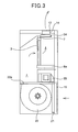
- Fig. 3 is a left side view showing the air filtering apparatus 1
- Fig. 4 is a right side view showing the air filtering apparatus 1.
- a pre-filter 21 is disposed inside the air suction port 15 formed in the housing 10.
- the pre-filter 21 captures pollen, dust, etc. contained in air sucked from the air suction port 15.
- This embodiment adopts a pre-filter 21 which can capture floated materials having particle sizes of 10 ⁇ m or more and floated in the air.
- an air blowing fan 22 is disposed in the pre-filter 21, and the air suction port of the air blowing fan 22 faces the air suction port 15 of the housing 10.
- an air flowing port 22a faces the top surface of the housing 10.
- the air blowing fan 22 is driven by a driving motor 23, and indoor air sucked from the air suction port 15 by the air blowing fan 22 is passed from the air flowing port 22a of the air blowing fan 22 through a passage indicated by an arrow of Fig. 3 to the gas-liquid contact member 3.
- the gas-liquid contact member 3 is provided on an air flowing path directing from the air suction port 15 to the air blow-out port 12, and it is disposed so as to be substantially erected in the housing 10.
- the air is filtered (i.e., the virus, etc. are inactivated or the like) while passing through the gas-liquid contact member 3, and the filtered air is passed through an air blowing filter 24 and fed from the air blow-out port 12 into the room again.
- the air filtering of the gas-liquid contact member 3 will be described later.
- An electrolytic water supply pipe 71 is disposed above the gas-liquid contact member 3, and the electrolytic water supply pipe 71 is connected to an electrolytic bath 4 shown in Figs. 2 and 4.
- water for example, well water or the like
- water containing chlorine ions for example, tap water (city water) or water added with chlorine ions
- tap water or the like Water or water containing chlorine ions (hereinafter referred to as "tap water or the like") stocked in the water supply tank 6 is supplied to the electrolytic bath 4 by the circulating pump 5.
- Awater spray box 7 electrolytic water supply unit
- electrolytic water is provided to the upper edge portion of the gas-liquid contact member 3, and electrolytic water is dropped from the spray box 7 into the gas-liquid contact member 3.
- the electrolytic water discharged from the gas-liquid contact member 3 is stocked in the water receiving portion (tray) 8a, and then flows to a water supply tank support tray 8b for supporting the water supply tank 6.
- the electrolytic water stocked in the water supply tank support tray 8b and tap water or the like supplied from the water supply tank 6 is pumped again by the circulating pump 5 and then supplied to the electrolytic bath 4.
- the water supply tank support tray 8b is provided with a drain valve (not shown), and the water (electrolytic water) in the water supply tank support tray 8b is discharged to a drain tray 9 by opening the drain valve.
- the drain tray 9 can be freely drawn out from a drain tray support portion 91, and a user or the like is allowed to discard the water in the drain water 9 and clean the drain tray 9.
- an electronic component box 25 is disposed between the air blowing fan 22 and the gas-liquid contact member 3 in the housing 10, and electrical component parts such as a control board, etc. (not shown) for controlling each part of the air filtering apparatus 1 are accommodated in the electric component box 25.
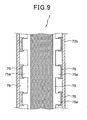
- the gas-liquid contact member 3 is a filter member having a homey comb structure. Accordingly, the gas-liquid contact area can be kept large, electrolytic water can be dropped, and clogging occurs hardly. That is, as shown in Fig. 5, the gas-liquid contact member 3 includes corrugated raw members 3A bent in a corrugated shape and flat-plate type raw members 3B, the corrugated raw members 3A and the flat-plate type raw members 3B being joined to one another, whereby they are assembled in a homey comb structure as a whole.
- the raw members 3A and 3B are formed of materials having little reactivity to electrolytic water as described later, that is, materials that are not deteriorated by the electrolytic water, for example, they are formed of polyolefin type resin (polyethylene resin, polypropylene resin or the like), PET (polyethylene-terephthalate) resin, vinyl chloride resin, fluorinated resin (PTFE, PFA, ETFE or the like), cellulose type material, ceramics type material or the like.
- PET resin is used for the members 3A and 3B.
- the gas-liquid contact member 5 may be subjected to a hydrophilic treatment to increase of the affinity to electrolytic water. Accordingly, the water retentivity (wettability) of the electrolytic water of the gas-liquid contact member 5 can be kept excellent, and the contact between active oxygen species and indoor air can be continued for a long time. Furthermore, electrolytic water having a mildewproof action is dropped to or infiltrated into the gas-liquid contact member 5, so that it is unnecessary to coat mildewcide on the gas-liquid contact member 5 as a countermeasure of proofing mildew.
- Fig. 6A is a diagram showing a supply state of electrolytic water to the gas-liquid contact member 3.
- the water receiving portion (tray) 8a is disposed below the gas-liquid contact member 3 of PET, and the water supply tank support portion (support tray) 8b which continuously intercommunicates with the water receiving portion 8a.
- the water supply port 6A of the water supply tank 6 and the circulating pump 5 are disposed in the water supply tank support tray 8 as shown in Fig. 6A. Tap water or the like stocked in the water supply tank 6 is supplied from the water supply port 6A to the water supply tank support tray 8b.
- the electrolytic bath 4 is connected to the circulating pump 5, and tap water or the like supplied to the water supply tank support tray 8b and electrolytic water flowing from the water receiving tray 8a to the water supply tank support tray 8b are supplied to the electrolytic bath 4 by the circulating pump 5.
- Fig. 6B is a diagram showing the internal structure of the electrolytic bath 4.
- the electrolytic bath 4 includes one or more pairs of electrodes 41 and 42, and by applying a voltage between the electrodes 41, 42, these electrodes 32, 33 electrolyze water or the like flowing into the electrolytic bath 4 to generate electrolytic water containing active oxygen species,
- the active oxygen species means oxygen molecules having higher oxidizing activity than normal oxygen and also related substance thereof, and contain not only so-called narrowly-defined active oxygen such as superoxide anion, singlet oxygen, hydroxyl radical and hydrogen peroxide, but also so-called broadly-defined active oxygen such as ozone, hypohalous acid, etc.
- the electrolytic bath 4 is disposed in the vicinity of the gas-liquid contact member 3 so that active oxygen species generated by electrolyzing water (tap water or the like) can be immediately supplied to the gas-liquid contact member 5.
- the electrodes 41, 42 are electrode plates each of which comprises a base of Ti (titan) and a coated layer of Ir (iridium), Pt (platinum).
- electrolytic water containing active oxygen species of predetermined concentration for example, free residual chlorine density of 1mg/l or the like
- concentration of the active oxygen species contained in the electrolytic water can be adjusted by adjusting the current value. Basically, by increasing the current value, the concentration of the active oxygen species in the electrolytic water can be increased.
- the polarities of the electrodes 41, 42 are inverted and water is electrolyzed while the cathode electrode is made to function as an anode electrode, thereby removing the scales depositing on the cathode electrode.
- the polarities may be periodically inverted by using a timer, for example, and the polarities may be irregularly inverted like the polarities are inverted every time the operation of the apparatus is started.
- increase of the electrolysis resistance decrease of electrolysis current or increase of electrolysis voltage
- the polarities may be inverted on the basis of the detection result.
- the electrolytic water supply pipe 71 inserted in the water spray box 7 is connected to the electrolytic bath 4. In the electrolytic bath 4, the electrolytic water thus generated is introduced to the electrolytic water supply pipe 71.
- the scales which are removed by inverting the polarities or the like flow out from the electrolytic bath 4 together with the electrolytic water, and are supplied to the gas-liquid contact member 3.
- electrolytic water containing insoluble materials such as scales, etc. (hereinafter referred to as “foreign materials”) is supplied to the gas-liquid contact member 3, it causes clogging of the gas-liquid contact member 3.
- the foreign materials passing through the gas-liquid contact member 3 are discharged to the water receiving tray 8a together with the electrolytic water.
- Foreign materials such as scales, etc. may be deposited from electrolytic water due to evaporation of water or the like.
- insoluble suspended substance such as colloidal silica, humic acid, etc. may be contaminated into the electrolytic water.
- these foreign materials may be returned to the electrolytic bath 4 again by the circulating pump 5, resulting in degradation of the electrolysis performance. Therefore, for example when scales are removed from the electrodes by the polarity inversion or the like, these scales are preferably withdrawn every time the polarities are inverted.
- a foreign material removing mechanism for removing foreign materials such as scales, etc. is provided in an electrolytic water supply path or electrolytic water circulating path (hereinafter referred to as electrolytic water supply/circulation path).
- a filter member 72 (Fig. 7) which is freely detachably mounted in the water spray box 7.
- the filter member 72 is exchanged by a new one, so that the maintenance can be easily performed and also the frequency of the maintenance itself can be reduced.
- electrolytic water can be supplied to the gas-liquid contact member 3 after foreign materials are removed from the electrolytic water concerned, so that the clogging, etc. of the gas-liquid contact member 3 can be prevented and the frequency and labor of the maintenance can be reduced.
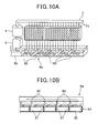
- Fig. 7 is a cross-sectional view
- Fig. 8 is a cross-sectional view taken in an arrow of X-X'
- Fig. 9 is a cross-sectional view taken in an arrow of Y-Y'.
- the water spray box 7 is assembled to the upper edge portion of the gas-liquid contact member 3, and it supplies electrolytic water to the gas-liquid contact member 3.
- the water spray box 7 is designed in the form of a box having no bottom.
- the water spray box 7 is mainly divided into an electrolytic water supply pipe unit 70a which is designed in the form of a box lid, and a filter unit 70b which is designed in the form of a box main body having no bottom.
- an insertion hole 73 through which an electrolytic supply pipe 71 is inserted is formed in the electrolytic water supply pipe unit 70a.
- the electrolytic water supply pipe unit 70a is detachable from the filter unit 70b under the state that the electrolytic water supply pipe 71 is inserted in the insertion hole 73.
- Many water spray holes 74 are formed at the lower portion of the electrolytic water supply pipe 71. Electrolytic water introduced from the electrolytic bath 4 is sprayed from the water spray holes 74 to the filter unit 70b.
- the filter unit 70b has an electrolytic water supply tray 75 for receiving electrolytic water sprayed from the electrolytic water supply pipe 71, a filter member 72 which is freely detachablymounted in the electrolytic water supply tray 75, a support portion(s) 76 for supporting the electrolytic water supply tray 75 and a water level sensor 77 for detecting the water level of the electrolytic water supply tray 75.
- plural electrolytic water supply holes 75b are formed in the bottom portion of the electrolytic water supply tray 75, and the electrolytic water sprayed from the electrolytic water supply pipe 71 is dropped from the electrolytic water supply holes 75b to the gas-liquid contact member 3.
- plural small piece portions 75a projecting outwardly from the electrolytic water supply tray 75 are provided to the upper edge of the electrolytic water supply tray 75 so as to be spaced from one another at predetermined intervals, and the small piece portions 75a are mounted on the support portion 76, whereby the electrolytic water supply tray 75 is supported on the support portion 76.
- the filter member 72 is fully laid on the whole surface of the bottom portion of the electrolytic water supply tray 75, and the electrolytic water sprayed to the electrolytic water supply tray 75 is filtered by the filter member 72 to remove foreign materials such as scales, humic acid, etc.
- the electrolytic water from which the foreign materials are removed is dropped from the electrolytic water supply holes 75b of the electrolytic water supply tray 75 to the gas-liquid contact member 3.
- the exchange timing of the filter member 72 can be known on the basis of the water level detected by the water level sensor 77.
- the operating panel 11 or the like may be equipped with an alarm lamp or the like which is turned on to indicate that the exchange timing of the filter member 72 has come when it is detected by the water level sensor 77 that the water level in the electrolytic water supply tray 75 reaches a predetermined water level, whereby a user or the like is informed of the exchange timing.
- the support portions 76 and the small piece portions 75a are arranged so as to be spaced from one another at predetermined intervals, and the gap between the neighboring the support portions 7 6 (small piece portions 75a) serves as an overflow port 78. That is, the electrolytic water overflowing from the electrolytic water supply tray 75 flows out from the overflow ports 78 to the lower portion.
- Slope pieces 79 which are downwardly sloped in cross-section are provided to the inner walls of the filter unit 70b so as to be disposed at the lower side of the electrolytic water supply tray 75.
- the electrolytic water flowing out from the over-flow ports 78 flows downwardly from the side walls of the electrolytic water supply tray 75 along the slope pieces 79, and drops from the gap between the slope pieces 79 to the gas-liquid contact member 3.
- the over-flow ports 78 and the slope pieces 79 provided to the inner walls of the filter unit 70b constitute a bypass passage of the electrolytic water.
- the water spray box 7 thus constructed is assembled to the upper edge portion of the gas-liquid contact member 3 in the filter unit 70b.
- the upper edge of the gas-liquid contact member 3 is provided with a sheet 31 for uniformly distributing the electrolytic water dropped from the water spray box 7 to the gas-liquid contact member 3.
- the operation of the on-floor mount type air filtering apparatus 1 is started.
- a circulating pump 5 shown in Fig. 6A is driven, and tap water or the like stocked in a water supply tank support tray 8b is supplied to the electrolytic bath 4.
- electrolytic water containing active oxygen species such as hypochlorous acid, ozone, hydrogen peroxide or the like is generated.
- This electrolytic water is introduced into the electrolytic water supply pipe 71, passed through the water spray holes 74 (not shown) of the electrolytic water supply pipe 71, sprayed to the electrolytic water supply tray 75 and then dropped to the gas-liquid contact member 3 from the electrolytic water supply hole 75b to the gas-liquid contact member 3 while foreign materials (scales, etc.) are removed from the electrolytic water by the filter member 72 mounted in the electrolytic water supply tray 75.
- the electrolytic water passes through the distributing sheet 31, and gradually infiltrates from the upper edge portion of the gas-liquid contact member 3 through the main body of the gas-liquid contact member 3 to the lower portion thereof.
- the air blowing fan 22 is driven by the driving motor 23, and indoor air sucked from the air suction port 15 by the air blowing fan 2 is passed from the air flowing port 22a of the air blowing fan 22 through a passage indicated by an arrow of Fig. 3 to the gas-liquid contact member 3.
- the gas-liquid contact member 3 into which electrolytic water infiltrates is supplied with the indoor air by the air blowing fan 22. This indoor air comes into contact with the active oxygen species contained in the electrolytic water infiltrating in the gas-liquid contact member 3, and then blown out from the air blow-out port 12 into the room again.
- the gas-liquid contact member 3 has high affinity to the electrolytic water. In this case, the water retentivity (wettability) of the gas-liquid contact member 3 to the electrolytic water is kept, and the contact between the indoor air and the active oxygen species can be continued for a long time.
- influenza virus invades into indoor air
- the active oxygen species function to break down and vanish (remove) the surface protein (spike) of the virus concerned which is indispensable for infection.
- the surface protein of influenza virus is broken down, the influenza virus is not joined to a receptor which is necessary for infection of the virus concerned, so that infection can be prevented.
- Sanitary Environment Research it has been found that when air in which influenza virus invades is passed through the gas-liquid contact member 3 of this embodiment, 99% or more of the virus concerned can be removed.
- the air filtering apparatus of this embodiment adopts a water circulating system, and a circulation path for electrolytic water is formed. Accordingly, when the amount of water is reduced due to vaporization or the like, a suitable amount of tap water or the like is supplied through the water supply tank 6 into the water supply tank support tray 8b. When the amount of water in the water supply tank 6 is reduced, the opening/closing lid 13 (see Fig. 1) is opened to take out the water supply tank 6, and tap water or the like is supplemented into the water supply tank 6.
- foreign materials such as scales such as calcium carbonate, magnesium carbonate, etc., insoluble materials such as humic acid, etc. can be withdrawn at one place by the foreign material removing mechanism such as the filter member 72 or the like.
- foreign materials can be withdrawn every time the foreign materials such as scales, etc. flow out from the electrolytic bath 4 together with the electrolytic water, and thus the frequency of the maintenance can be reduced.
- a work of withdrawing scales removed from the electrodes 41, 42 is not required to be carried out every time the pole switching operation of the electrodes is periodically carried out, and thus the frequency of the maintenance can be reduced.
- electrolytic water is supplied to the gas-liquid contact member 3 after foreign materials are removed from the electrolytic water, and thus foreign materials such as scales, humic acid, etc. can be prevented from adhering to the gas-liquid contact member 3, and thus the frequency of the maintenance of the gas-liquid contact member 3 can be reduced.
- the filter member 72 is freely detachably mounted in the electrolytic water supply tray 75, and thus when the filter member 72 is clogged with foreign materials, the filter member 72 can be easily exchanged and the labor of the maintenance can be reduce as compared with the case where the gas-liquid contact member 3 itself is exchanged.
- the water spray box 7 is designed in a box-shape, and it has the electrolytic water supply pipe unit 70a designed like a box lid, and the filter unit 70b designed like a box main body. Therefore, when the filter member 72 is exchanged, the electrolytic water supply pipe unit 70a can be easily detached from the filter unit 70b and the maintenance can be easily performed.
- the filter member 72 when the filter member 72 is clogged in the electrolytic water supply tray 75, the water level of the electrolytic water in the electrolytic water supply tray 75 increases. Therefore, on the basis of the water level detected by the water level sensor 77, a user, a maintenance manager or the like can grasp the exchange timing of the filter member 72. At this time, if the exchange timing of the filter member is informed to the user by turning on a lamp on the operation panel 11 or the like when the water level in the electrolytic water supply tray 75 reaches to a predetermined water level, for example, the water level at which the filter member 72 should be exchanged, the user, the maintenance manager or the like can easily grasp the exchange timing of the filter member 72.
- a predetermined water level for example, the water level at which the filter member 72 should be exchanged
- the over-flowing electrolytic water can be supplied to the gas-liquid contact member 3 through the bypass path. Therefore, even when the filter member 72 is not exchanged although the exchange timing of the filter member 72 has elapsed, it is possible to supply the electrolytic water to the gas-liquid contact member 3 and continue the operation of the air filtering apparatus.
- electrolytic water containing hypochlorous acid is collected in the water receiving tray 8a, and flows to the adjacent water supply tank support tray 8b. Therefore, fungus, etc. do not occur in the trays 8a, 8b, and occurrence of slime can be prevented. Therefore, the frequency of cleaning and maintenance of the trays 8a, 8b can be reduced, and the labor of the maintenance, etc. can be also reduced.
- the foreign materials such as scales, insoluble materials, etc. occurring in the electrolytic bath 4, etc. are removed by the filtering mechanism of the filter member 72 interposed between the electrolytic water supply pipe 71 and the gas-liquid contact member 3, whereby the foreign materials such as scales, etc. can be removed from the circulating system of the electrolytic water.
- the foreign material removing mechanism is not limited to the filtering mechanism based on the filter member 72, and any me chan ism may be adopted in place of the filtering mechanism insofar as it can remove foreign materials such as scales, etc. Furthermore, if such a mechanism is used in combination with the filtering mechanism, the foreign material removing effect can be more enhanced.
- a foreign material trap mechanism is provided to the water receiving tray to remove foreign materials from the circulating system of the electrolytic water.
- the construction of the foreign material trap mechanism will be described in detail with reference to Figs. 10A, 10B and 11.
- Foreign materials such as scales, etc. which are removed from the electrodes by reversing the polarities of the electrodes 41, 42 (i.e., pole changing operation) are passed through the gas-liquid contact member 3 together with the electrolytic water and then discharged to the water receiving tray 8a.
- the electrolytic water overflowing from the electrolytic water supply tray 75 contains foreign materials. In this case, these foreign materials may pass through the gas-liquid contact member 3 to the water receiving tray 8a.
- the water receiving tray 8a is provided with a dam member for damming (trapping) foreign materials such as scales, etc. contained in electrolytic water from the gas-liquid contact member 3 and preventing the foreign materials from flowing out from the water receiving tray 8a to the water supply tank support tray 8b when the electrolytic water in the water receiving tray 8a is supplied through the water supply tank support tray 8b to the electrolytic bath 4 by the circulating pump 5.
- the dam member comprises one or plural dams 80 arranged from the upstream side to the downstream side with respect to the flow of the electrolytic water which occurs in the water receiving tray 8a due to the electrolytic water supply operation to the electrolytic bath 4 by the circulating pump 5.
- the water receiving tray 8a is provided with one or plural discharge valves 81 for discharging the foreign materials such as scales, etc. trapped by the dams 80 from the water receiving tray 8a to the outside together with the electrolytic water.
- Each discharging valve 81 is provided at the upstream side of each dam 80, and each discharging valve 81 is connected to a drain tube 82.
- the drain tube 82 is connected to a drain tray 9, and the electrolytic water and the foreign materials in the water receiving tray 8a are discharged through the drain tube 82 to the drain tray 9.
- the operation of the on-floor mount type air filtering apparatus 1 is started.
- the circulating pump 5 of Fig. 10A is driven, and tap water or the like stocked in the water supply tank support tray 8b is pumped up and supplied to the electrolytic bath 4.
- electrolytic bath 4 a predetermined voltage is applied between the electrodes 41, 42, and DC current flows between the electrodes 41 and 42 to electrolyze tap water or the like, whereby electrolytic water containing hypochlorous acid, ozone and hydrogen peroxide is generated.
- This electrolytic water is introduced into the electrolytic water supply pipe 71, passed through the water spray holes 74 (not shown) of the electrolytic water supply pipe 71, and then dropped to the gas-liquid contact member 3.
- the electrolytic water gradually infiltrates from the upper edge portion of the gas-liquid contact member 3 through the main body thereof to the lower portion while coming into contact with the indoor air sucked from the air suction port 15 by the air blowing fan 22.
- the discharge valves 81 provided in the water receiving tray 8a and a drain valve (not shown) provided in the water supply tank support tray 8b are opened, whereby the electrolytic water stocked in the water receiving tray 8a and the water supply tank support tray 8b can be drained to the drain tray 9. Furthermore, the foreign materials such as scales, etc. trapped by the dams 80 are discharged from the discharge valves 81 to the drain tray 9 together with the electrolytic water.
- the dams 80 are provided to the water receiving tray 8a for receiving electrolytic water discharged from the gas-liquid contact member 3. Therefore, the foreign materials contained in the electrolytic water discharged from the gas-liquid contact member 3 are withdrawn at the water receiving tray 8a, so that these foreign materials can be prevented from returning to the electrolytic bath 4. Therefore, the electrolysis performance of the electrolytic bath 4 and the durability of the electrodes 41, 42 can be kept, and the frequency of the maintenance for withdrawing foreign materials such as scales, etc. can be reduced.
- the plural dams 80 are provided in the water receiving tray 8a so as to be arranged along the direction from the upstream side to the downstream side with respect to the flow direction of the electrolytic water from the water receiving tray 8a to the water supply tank support tray 8b. Therefore, even when the amount of foreign materials contained in electrolytic water is large, the foreign materials can be damped at each dam 80. Accordingly, the foreign materials such as scales, etc. can be more surely prevented from flowing out from the water receiving tray 8a to the water supply tank support tray 8b, so that the foreign materials can be more surely prevented from being pumped up by the circulating pump 5 and returned to the electrolytic bath 4. Therefore, the frequency of the maintenance can be reduced.
- the discharge valves 81 for discharging the foreign materials such as scales, etc. dammed by the dams 80 from the water receiving tray 8a together with the electrolytic water are provided in the water receiving tray 8a. Therefore, the foreign materials such as scales, etc. dammed by the dams 80 can be discharged from the water receiving tray 8a together with the electrolytic water.
- the electrolytic water and the foreign materials such as scales, etc. are discharged through the drain tube 82 to the drain tray 9.
- the drain tray 9 is configured to be freely drawn out from the drain tray support portion 91. Therefore, the maintenance work of drawing out the drain tray 9 from the drain tray support portion 91, discharging the electrolytic water in the drain tray 9 and remove the foreign materials such as scales, etc. can be easily performed.
- calcium-based scales and magnesium-based scales generated in the electrolytic bath 4 are mainly described as foreign materials.
- the foreign materials trapped in the water receiving tray 8a by the dams 80 may contain scales which are generated when water in the gas-liquid contact member 3 and the water receiving tray 8a is vaporized and thus the electrolytic water is condensed (for example, calcium-based scales, silica-based scales).
- a deposition promoting member for depositing scale components contained in electrolytic water discharged from the gas-liquid contact member 3 may be provided in the water receiving tray 8a.
- the scale components contained in the electrolytic water are deposited by the deposition promoting member, and the scales can be dammed by the dams 80 and withdrawn, so that the scales can be efficiently removed.
- a porous ceramic member may be used as the deposition promoting member.
- the water receiving tray (water receiving portion) 8a and the water supply tank support tray (electrolytic water stock portion) 8b may be configured as separate tray-like members so as to be continuously connected to each other, or they may be configured as a unified tray-like member as shown in Figs. 10A, 10B.
- the heights of the dams 80 provided to the water receiving tray 8a (water receiving portion) may be set so that all the dams 80 have the same height or the dam 80 at the water supply tank support tray 8b side is higher than the height of the other dams 80.
- the height of the dams 80 is suitably adjustable in accordance with the amount of foreign materials (scales, etc.) contained in the electrolytic water discharged from the gas-liquid contact member 3 and the specific construction of the water receiving portion and the stock portion.
- the dams 80 provided in the water receiving tray 8a may be formed of filter members, and the bottom surface of the water receiving tray 8a may be configured to be arbitrarily inclined so that the upstream side of the bottom surface is higher than the downstream side of the bottom surface at the water supply tank support tray 8b.
- large scales having large particle sizes are precipitated and deposited in front of each dam 80, and scales having small particle sizes and colloidal scales floated in the water are captured by the filter members, so that only electrolytic water from which foreign materials are filtered can be made to flow to the water supply tank support tray 8b.
- a drain hole may be provided in front of each dam 80, and a discharge valve 81 for opening/closing the drain hole may be provided to the drain hole. In this case, by opening the drain valve 81, foreign materials such as scales, etc.
- the discharge valve 81 may be configured to open/close the drain hole itself or the flow path of the drain tube 82 connected to the drain hole. The same is applicable to the construction of Fig. 10B.
- electrolytic water containing hypochlorous acid or the like is collected in the water receiving tray 8a, and flows to the water supply tank support tray 8b. Therefore, no microorganism such as virus, bacteria, fungus, etc. occurs in each tray 8a, 8b, and occurrence of slime can be prevented. Therefore, the frequency of the cleaning and maintenance of each tray 8a, 8b can be reduced, and the labor of the maintenance, etc. can be reduced.
- a water supply system based on the water supply tank 6 which can be freely taken in and out is adopted.
- a water pipe supply system in which a tap water pipe is connected to the air filtering apparatus to directly introduce tap water (city water) may be adopted.
- the electrolytic water supply unit of dropping electrolytic water to the gas-liquid contact member 3 so that the electrolytic water infiltrates into the gas-liquid contact member 3 is adopted.
- the present invention is not limited to this mode, and electrolytic water may be made to infiltrate into the gas-liquid contact member 3 by a suction system.
- two dams are provided in the water receiving tray 8a, and there are formed a foreign material removing area in which electrolytic water is introduced and the filter member 72 is freely detachably mounted to remove foreign materials such as scales, etc. contained in electrolytic water, and an electrolytic water holding area which is adjacent to the foreign material removing area and stocks electrolytic water from which foreign materials are removed in the foreign material removing area.
- the lower edge portion of the gas-liquid contact member 3 is submerged in the electrolytic water in the electrolytic water holding area, and the electrolytic water is sucked by a so-called capillary phenomenon.
- the above embodiment mainly relates to the construction of generating hypochlorous acid as active oxygen species.
- the construction of generating ozone (O 3 ), hydrogen peroxide (H 2 O 2 ) or the like as active oxygen species may be adopted.
- active oxygen species can be highly efficiently and stably generated from water in which ion species are rare (for example, well water).
- ozone (O 3 ) and hydrogen peroxide (H 2 O 2 ) which have strong sterilizing power are generated by supplying current to the electrodes 41, 42 in the electrolytic bath 4, and electrolytic water containing ozone (O 3 ) and hydrogen peroxide (H 2 O 2 ) can be created and supplied to the gas-liquid contact member 3.
- indoor air sucked from the air suction port 15 provided to the front surface of the housing 10 is brought into contact with electrolytic water dropped to the gas-liquid contact member 3, and then blown out from the air blow-out port 12 provided to the upper portion of the housing 10. Therefore, even when the on-floor mount type air filtering apparatus 1 is set up in a so-called large space such as a kindergarten, an elementary/junior high/high school, long-term care insurance facilities, a hospital or the like, indoor air which comes into contact with the electrolytic water and thus filtered (i.e., sterilized, inactivated or the like) can be blown out far away in the large space, so that the filtering (sterile filtration, etc.) of air can be efficiently performed in the large space. At the same time, deodorization can be performed.
- filtered i.e., sterilized, inactivated or the like
- the foreign material removing mechanism is disposed in the electrolytic water supply/circulating passage, particularly at the upstream side of the gas-liquid contact member (i.e., in the electrolytic water supply unit) or at the downstream side of the gas-liquid contact member (i.e., in the water receiving portion).
- the present invention is not limited to these embodiments. They may be set up at any place in the electrolytic water supply/circulating passageinsofarasforeign materials such as scales, etc. can be removed.
- the setup position is not limited to one place, and plural same type or different type foreign material removing mechanism may be set up at different places. Alternatively, these foreign material removing mechanisms may be set up at at least one place in combination.
Landscapes
- Engineering & Computer Science (AREA)
- Chemical & Material Sciences (AREA)
- Combustion & Propulsion (AREA)
- Mechanical Engineering (AREA)
- General Engineering & Computer Science (AREA)
- Life Sciences & Earth Sciences (AREA)
- Health & Medical Sciences (AREA)
- Sustainable Development (AREA)
- Epidemiology (AREA)
- Animal Behavior & Ethology (AREA)
- General Health & Medical Sciences (AREA)
- Public Health (AREA)
- Veterinary Medicine (AREA)
- Materials Engineering (AREA)
- Water Treatment By Electricity Or Magnetism (AREA)
- Disinfection, Sterilisation Or Deodorisation Of Air (AREA)
- Separation Of Particles Using Liquids (AREA)
Applications Claiming Priority (2)
| Application Number | Priority Date | Filing Date | Title |
|---|---|---|---|
| JP2006197930A JP4744381B2 (ja) | 2006-07-20 | 2006-07-20 | 空気除菌装置 |
| JP2006199381A JP2008023098A (ja) | 2006-07-21 | 2006-07-21 | 空気除菌装置 |
Publications (2)
| Publication Number | Publication Date |
|---|---|
| EP1881274A2 true EP1881274A2 (fr) | 2008-01-23 |
| EP1881274A3 EP1881274A3 (fr) | 2009-07-22 |
Family
ID=38610615
Family Applications (1)
| Application Number | Title | Priority Date | Filing Date |
|---|---|---|---|
| EP07013837A Withdrawn EP1881274A3 (fr) | 2006-07-20 | 2007-07-13 | Appareil de filtrage d'air ayant un mécanisme de suppression de matériau étranger |
Country Status (5)
| Country | Link |
|---|---|
| US (1) | US7850769B2 (fr) |
| EP (1) | EP1881274A3 (fr) |
| KR (1) | KR100883011B1 (fr) |
| CN (1) | CN101108255A (fr) |
| MY (1) | MY149598A (fr) |
Families Citing this family (16)
| Publication number | Priority date | Publication date | Assignee | Title |
|---|---|---|---|---|
| JP5227663B2 (ja) * | 2008-05-30 | 2013-07-03 | 三洋電機株式会社 | 空気調和除菌システム |
| US8397523B2 (en) * | 2008-05-30 | 2013-03-19 | Sanyo Electric Co., Ltd. | Electrolytic water generating device, air filtering system, air conditioning and filtering apparatus, and air conditioning and filtering system |
| US9534801B2 (en) * | 2008-11-28 | 2017-01-03 | Lg Electronics Inc. | Humidifier |
| WO2010091553A1 (fr) * | 2009-02-13 | 2010-08-19 | Mass Technology (H.K.) Limited | Procédé et appareil pour produire électrolytiquement de l'eau alcaline, et utilisation de l'eau alcaline produite |
| JP5627382B2 (ja) * | 2010-10-12 | 2014-11-19 | 三菱電機株式会社 | マンコンベア |
| CN104121629A (zh) * | 2013-04-26 | 2014-10-29 | 孙友谊 | 室内空气净化装置 |
| CN104226053B (zh) * | 2013-06-07 | 2016-08-10 | 林兆钧 | 粉尘过滤扇 |
| KR20150019400A (ko) * | 2013-08-13 | 2015-02-25 | 삼성전기주식회사 | 인쇄회로기판 제조공정용 정화장치 및 이를 이용한 정화방법 |
| CN104949211B (zh) * | 2014-03-27 | 2018-03-02 | 圣太科电子(珠海)有限公司 | 一种带有消毒功能的空气净化器 |
| CN103933847A (zh) * | 2014-04-17 | 2014-07-23 | 顾立强 | 盐溶液电解式水滤网空气过滤器 |
| CN105042687B (zh) * | 2015-06-30 | 2018-02-23 | 东莞市华生益环保净化科技有限公司 | 一种节能型空气消毒过滤器 |
| CN106051923B (zh) * | 2016-07-15 | 2021-12-03 | 广东美的制冷设备有限公司 | 壁挂式空调室内机和空调器 |
| JP7113371B2 (ja) * | 2018-09-21 | 2022-08-05 | パナソニックIpマネジメント株式会社 | 空気清浄装置 |
| US10955156B1 (en) * | 2019-12-11 | 2021-03-23 | Sten Kreuger | Air conditioning and humidity control system and methods of making and using the same |
| KR102346882B1 (ko) * | 2020-01-23 | 2022-01-04 | 나기원 | 전해수를 이용한 스탠드형 공기 살균소독기 |
| CN112484225A (zh) * | 2020-12-04 | 2021-03-12 | 山东美华环境科技有限公司 | 一种智能空气净化装置 |
Family Cites Families (18)
| Publication number | Priority date | Publication date | Assignee | Title |
|---|---|---|---|---|
| US2117378A (en) * | 1935-11-07 | 1938-05-17 | Tiffany Products Corp | Settling and coagulating agent and the method for making and using the same |
| US5492620A (en) * | 1993-03-31 | 1996-02-20 | Evans; Steven T. | Apparatus for removing contaminants from a waste stream |
| US5626748A (en) * | 1995-04-27 | 1997-05-06 | Rose William C | Liquid separator |
| US5939031A (en) * | 1996-08-23 | 1999-08-17 | Exxon Research And Engineering Co. | Countercurrent reactor |
| US6086055A (en) * | 1998-10-05 | 2000-07-11 | Air Products And Chemicals, Inc. | Combined vapor/liquid distributor for packed columns |
| JP2000189975A (ja) * | 1998-12-24 | 2000-07-11 | Matsushita Electric Ind Co Ltd | 電極皮膜の除去方法およびその方法を用いた水浄化装置 |
| JP2000257914A (ja) * | 1999-03-05 | 2000-09-22 | Techno Ryowa Ltd | 強酸性水を用いた除菌空調システム |
| JP2001219171A (ja) * | 2000-02-10 | 2001-08-14 | Matsushita Electric Ind Co Ltd | 水浄化装置 |
| JP2002079248A (ja) * | 2000-09-06 | 2002-03-19 | Tominaga Oil Pump Mfg Co Ltd | 電解水生成装置 |
| US6367782B1 (en) * | 2000-09-12 | 2002-04-09 | Research Products Corporation | Water distributor |
| JP2002181358A (ja) | 2000-10-04 | 2002-06-26 | Denso Corp | 加湿装置および加湿装置付き空調装置 |
| US6843835B2 (en) * | 2001-03-27 | 2005-01-18 | The Procter & Gamble Company | Air cleaning apparatus and method for cleaning air |
| US6623551B2 (en) * | 2001-09-12 | 2003-09-23 | Durr Industries, Inc. | Baffle system for separating liquid from a gas stream |
| KR100517408B1 (ko) * | 2003-07-03 | 2005-09-27 | 삼성전자주식회사 | 오염 제어 시스템 및 이를 이용한 기판 처리 장치의공조시스템 |
| JP4471742B2 (ja) * | 2004-03-26 | 2010-06-02 | 三洋電機株式会社 | 空気調和機および電解水噴霧装置 |
| KR100621849B1 (ko) * | 2004-12-22 | 2006-09-19 | 류기헌 | 공기 정화 시스템 |
| US7506861B2 (en) * | 2005-01-21 | 2009-03-24 | Morten Muller Ltd. Aps | Distribution device for two-phase concurrent downflow vessels |
| US7445198B2 (en) * | 2006-08-30 | 2008-11-04 | Uop Llc | Apparatus and process for distributing liquid |
-
2007
- 2007-07-11 MY MYPI20071116A patent/MY149598A/en unknown
- 2007-07-13 EP EP07013837A patent/EP1881274A3/fr not_active Withdrawn
- 2007-07-18 US US11/779,431 patent/US7850769B2/en not_active Expired - Fee Related
- 2007-07-19 KR KR1020070072106A patent/KR100883011B1/ko not_active Expired - Fee Related
- 2007-07-20 CN CNA200710137370XA patent/CN101108255A/zh active Pending
Non-Patent Citations (1)
| Title |
|---|
| None * |
Also Published As
| Publication number | Publication date |
|---|---|
| US7850769B2 (en) | 2010-12-14 |
| CN101108255A (zh) | 2008-01-23 |
| US20080017039A1 (en) | 2008-01-24 |
| KR20080008973A (ko) | 2008-01-24 |
| MY149598A (en) | 2013-09-13 |
| KR100883011B1 (ko) | 2009-02-12 |
| EP1881274A3 (fr) | 2009-07-22 |
Similar Documents
| Publication | Publication Date | Title |
|---|---|---|
| US7850769B2 (en) | Air filtering apparatus having foreign material removing mechanism | |
| US7857897B2 (en) | Air filtering apparatus | |
| US7896947B2 (en) | Air filtering apparatus | |
| KR101035609B1 (ko) | 공기제균장치 | |
| US7850768B2 (en) | Air filtering apparatus having scale removal detecting mechanism | |
| KR101095410B1 (ko) | 공기제균장치 | |
| CN101130100A (zh) | 具有异物除去机构的空气除菌装置 | |
| CN101623509A (zh) | 空气除菌装置 | |
| JP4753823B2 (ja) | 空気除菌装置 | |
| JP2008183182A (ja) | 空気除菌装置 | |
| EP1798493A2 (fr) | Appareil de filtrage de l'air | |
| EP1891982A2 (fr) | Appareil de filtrage d'air ayant un mécanisme de suppression de matériau étranger | |
| CN101172163A (zh) | 空气除菌装置 | |
| EP2145631B1 (fr) | Dispositif de filtrage d'air | |
| JP2011177293A (ja) | 空気除菌装置 | |
| EP1953462A2 (fr) | Appareil de filtrage de l'air | |
| JP4878820B2 (ja) | 床置き式空気除菌装置 | |
| EP1788315A2 (fr) | Dispositif de filtration d'air monté sur le sol | |
| JP4878836B2 (ja) | 床置き式空気除菌装置 | |
| JP4721921B2 (ja) | 空気除菌装置 | |
| KR100839297B1 (ko) | 공기 제균 장치 | |
| JP4744381B2 (ja) | 空気除菌装置 | |
| JP2008023098A (ja) | 空気除菌装置 | |
| JP2008125570A (ja) | 空気除菌装置 |
Legal Events
| Date | Code | Title | Description |
|---|---|---|---|
| PUAI | Public reference made under article 153(3) epc to a published international application that has entered the european phase |
Free format text: ORIGINAL CODE: 0009012 |
|
| 17P | Request for examination filed |
Effective date: 20070713 |
|
| AK | Designated contracting states |
Kind code of ref document: A2 Designated state(s): AT BE BG CH CY CZ DE DK EE ES FI FR GB GR HU IE IS IT LI LT LU LV MC MT NL PL PT RO SE SI SK TR |
|
| AX | Request for extension of the european patent |
Extension state: AL BA HR MK YU |
|
| PUAL | Search report despatched |
Free format text: ORIGINAL CODE: 0009013 |
|
| AK | Designated contracting states |
Kind code of ref document: A3 Designated state(s): AT BE BG CH CY CZ DE DK EE ES FI FR GB GR HU IE IS IT LI LT LU LV MC MT NL PL PT RO SE SI SK TR |
|
| AX | Request for extension of the european patent |
Extension state: AL BA HR MK RS |
|
| AKX | Designation fees paid |
Designated state(s): DE FR GB HU IT |
|
| 17Q | First examination report despatched |
Effective date: 20100323 |
|
| STAA | Information on the status of an ep patent application or granted ep patent |
Free format text: STATUS: EXAMINATION IS IN PROGRESS |
|
| GRAP | Despatch of communication of intention to grant a patent |
Free format text: ORIGINAL CODE: EPIDOSNIGR1 |
|
| STAA | Information on the status of an ep patent application or granted ep patent |
Free format text: STATUS: GRANT OF PATENT IS INTENDED |
|
| INTG | Intention to grant announced |
Effective date: 20180608 |
|
| STAA | Information on the status of an ep patent application or granted ep patent |
Free format text: STATUS: THE APPLICATION IS DEEMED TO BE WITHDRAWN |
|
| 18D | Application deemed to be withdrawn |
Effective date: 20181019 |